DOI:
10.1039/D4RA03590A
(Paper)
RSC Adv., 2024,
14, 33191-33197
An optimized heating source for heat-not-burn tobacco products through synergistic combustion of tobacco stalk and graphite carbon with K2CO3 catalyst
Received
16th May 2024
, Accepted 14th October 2024
First published on 21st October 2024
Abstract
Waste tobacco stalk is blended with graphite carbon to form a composite carbon source, which is a promising external heating system for heat-not-burn tobaccos. In the current work, the effects of tobacco stalk amounts and the catalyst K2CO3 on the co-combustion characteristics (i.e., the ignition temperature, burnout temperature, etc.) of graphite carbon were investigated. As a result, the ignition temperatures of the blend were determined by the tobacco straw, while the burnout temperature of the samples was reduced by approximately 60 °C due to the addition of a tobacco stalk. After the addition of K2CO3, the ignition temperatures of the mixture were further decreased by 2–7 °C since the ignition temperature of the tobacco stalk was difficult to further reduce after K2CO3 addition. Meanwhile, the burnout temperature can be reduced by 76–106 °C because the presence of K2CO3 can significantly improve the combustion of graphite carbon. In addition, the kinetic analysis revealed that during the release of volatile matter, the oxidation process accords with the first-order kinetic model, while in the combustion process of mixed carbon source, the combustion process can be described by the third-order kinetic model.
Introduction
Heat-not-burn (HNB) tobacco products have lower indoor ambient smoke concentrations and toxic chemical substances compared to traditional cigarettes.1,2 In our previous studies,3,4 a fuel element composed of two carbon sources, performed very well in HNB external heating systems. As a large tobacco-producing country, China's tobacco production reached 213 million tons in 2020, according to a report released in 2021.5 During the production and manufacturing of finished tobacco products, a large amount of tobacco waste is inevitably generated, including tobacco leaves and stems produced during cultivation, as well as the wastes generated during the re-roasting process, such as crushed tobacco ends and long stems.6 In the past, tobacco waste was often incinerated or landfilled, wasting resources, polluting the air, and contaminating groundwater with harmful chemicals.6 Clean, efficient use of tobacco stalk waste is environmentally important and economically beneficial.7 This work aims to investigate the co-combustion behaviors of the graphite carbon and tobacco stalk, as well as the effect of combustion improver on the co-combustion characteristics.
In recent years, the literature published on the disposal of tobacco waste vial novel approaches mainly includes (1) preparation of bio-oil, biochar, and biogas by pyrolysis;5,8–10 (2) preparation of high-energy solid fuels, high-value nitrogenous compounds, phenolic compounds, and prebiotic oligosaccharides by hydrothermal carbonation, liquefaction, and pre-treatment, respectively.11–13 However, the methods mentioned above are difficult for large-scale industrial production because they require long processing times and costly, complicated procedures. An effective way to solve this problem is to use tobacco waste as a biofuel for combustion to release energy like other types of lignocellulosic biomass.14 However, tobacco wastes have some inherent disadvantages, such as low calorific value, high moisture, high oxygen content, and high alkaline earth metal content, which make them unsuitable for direct combustion on a large scale.11 Therefore, tobacco waste has also been widely used to improve poor-quality coal combustion. Studies have shown that tobacco stalks can provide heat for the combustion of high ash anthracite15 and high sulfur coals,16 thus improving their ignition properties. When tobacco stalks and low rank coal are mixed, they produce an inhibitory effect before ignition, which is gradually transformed into a facilitating effect as the temperature rises and reduces the burnout temperature.17 In addition, due to the two materials' different ignition/burnout temperatures, their blending carbon source may reduce the proportion of low-temperature volume in the heating system, thereby reducing CO emissions.18 Hence, the carbon source prepared from tobacco stalk and substantially non-burning graphite can be a viable and promising way to improve the co-combustion characteristics, which can also be used as a fuel element for the external heating system in HNB tobacco.
In our previous study, chrysanthemum biochar was used as a carbon source to form fuel element, demonstrating excellent performance in small-scale tests. However, chrysanthemum biochar is typically derived from wood and requires a high-temperature carbonization process, making it costly for large-scale production of HNB (Heat-Not-Burn) tobacco products. This work aims to investigate the co-combustion characteristics of tobacco stems with graphite carbon, a more cost-effective and environmentally friendly carbon source, to replace expensive chrysanthemum biochar. The co-combustion characteristics of the tobacco stems and graphitic carbon mixtures of with/without potassium catalyst were investigated using experimental and kinetic methods, respectively. The ignition and burnout temperature of the carbon mixtures were determined by thermal gravimetric (TG) analysis, and the activation energy and the prompting mechanism of potassium salt were obtained through kinetic model calculation. Moreover, a scanning electron microscope (SEM) was adopted to observe the surface morphology of the carbon mixture, and an energy dispersive spectrometry (EDS) was coupled to examine the surface elemental distribution. The obtained results can provide experimental support for the preparation of carbon heating sources in HNB tobacco products.
Material and methods
Material and samples
The purchased tobacco stalk was finely ground. The powder of as-prepared tobacco stalk and graphite carbon were both sieved to 200 mesh (<75 μm) for further utilization. The elemental composition was characterized by an elemental analyzer (UNICUBE, Elementar, D.E.). The amounts of carbon, hydrogen, nitrogen, and sulfur were measured through combustion, and oxygen content was determined by difference.
Table 1 shows the proximate and ultimate analysis of the tobacco stalk and graphite carbon by air-dried basis, indicating the tobacco stalk has 7.03 wt% of moisture (M), 18.53 wt% of ash (A), 62.01 wt% of volatile matters (VM) and 12.43 wt% of fixed carbon (FC). Further examination of the elemental composition of tobacco stalk highlights a significantly higher A content compared to typical biomass sources.19 The as-prepared graphite carbon/tobacco stalk powders were dehydrated at 105 °C for 4 hours and then stored in a sealed drying container with the desiccants at the bottom.
Table 1 Proximate and ultimate analysis of the tobacco stalks and graphite carbon (graphite carbon data from previous work4)
| Proximate analysis (air dried basis, wt%) |
| Material |
M |
A |
VM |
FC |
| Tobacco stalk |
7.03 |
18.53 |
62.01 |
12.43 |
| Graphite |
0.61 |
0.37 |
3.73 |
95.29 |
| Ultimate analysis (air dried basis, wt%) |
| Material |
C |
H |
O |
N |
S |
| Tobacco stalk |
37.38 |
5.01 |
55.81 |
1.61 |
0.19 |
| Graphite |
99.37 |
0.36 |
0.15 |
0.07 |
0.05 |
To further investigate the co-combustion characteristics, blends of tobacco stalk and graphite carbon were prepared in varying ratios, as outlined in Table 2. Potassium carbonate (K2CO3) was utilized as the combustion catalyst. The samples are named according to the following rules: The samples are named according to the following rules: ‘SG’ denotes the combination of tobacco stalk (S) and graphite carbon (G); the numerical suffix reflects the mass fraction of graphite carbon, and ‘K’ signifies the blend containing K2CO3.
Table 2 The mass fraction of the co-combustion mixtures
| Sample |
Tobacco stalk |
Graphite |
K2CO3 |
| SG1 |
90.00 |
10.00 |
0.00 |
| SG2 |
80.00 |
20.00 |
| SG3 |
70.00 |
30.00 |
| SG4 |
60.00 |
40.00 |
| SG5 |
50.00 |
50.00 |
| SGK1 |
89.10 |
9.90 |
1.00 |
| SGK2 |
79.20 |
19.80 |
| SGK3 |
69.30 |
29.70 |
| SGK4 |
59.40 |
39.60 |
| SGK5 |
49.50 |
49.50 |
The inclusion of control groups with 0.00 wt% and 1.00 wt% of K2CO3 was motivated by two factors. Firstly, in our preceding research,3,4 it was determined that 1 wt% of K2CO3 serves as an adequate combustion enhancer, eliminating the need to assess the influence of mass fraction on co-combustion in the present study. Secondly, the precise role played by the potassium catalyst during the co-combustion of graphite carbon and tobacco stalk powders remains elusive and warrants additional examination.
To achieve adequate mixing, tobacco stalk, graphite, and potassium salt were mixed in ethanol solution due to the poor wettability of graphite in water. Specifically, SG1 was prepared by following the procedures below: tobacco stalk of 9.0 g and graphite of 1.0 g were mixed with 20 mL of 50 vol% ethanol solution to generate the suspension, which was stirred and dehydrated at 105 °C for 8 h to yield SG10. Similarly, SG2–5 were produced by adjusting the ratios of tobacco stalk to graphite while maintaining the same procedures. Additionally, SGK1 was prepared by mixing 8.91 g of tobacco stalk, 0.99 g of graphite, and 0.1 g of K2CO3 with 20 mL of 50 vol% ethanol solution. For SGK2–5, the blending ratio of K2CO3 was consistently maintained at 1.00 wt%, with the mass ratios of tobacco stalks to graphite corresponding to those of SG1–SG5, respectively.
TG-DSC analysis
To gain a comprehensive understanding of the co-combustion characteristics of tobacco stalk blended with varying contents of graphite carbon, a detailed thermal gravimetric (TG) analysis was performed using a high-precision NETZSCH instrument (STA 449F3, D.E.), ensuring accurate and reliable results. During the experiment, 10 mg of finely ground sample was carefully placed in a platinum crucible. The sample was then subjected to a controlled heating process, heated from the room temperature to 1000 °C at 10 °C min−1 in flowing air of 100 mL min−1. As the sample heated, the TG analyzer continuously recorded the weight loss curve, providing valuable insights into the combustion behavior of the blend. Additionally, differential scanning calorimetric (DSC) curves were simultaneously collected by an online computer and data processing system, offering further insights into the thermal properties of the material.
SEM-EDS analysis
The patterns were then analyzed using diffraction pattern matching software to identify the potential mineral phases present in the samples. Scanning electron microscopy (SEM) was conducted on a scanning electron microscope (SU 8010, Hitachi, J.P.) equipped with an energy-dispersive X-ray spectroscope (EDS) to analyze the morphology and composition of the samples. All the meticulously homogenized samples were coated with platinum to enhance their conductivity and visibility under the SEM. The accelerating voltage used for the SEM analysis was 2 kV.
Results and discussion
The co-combustion properties of the blends
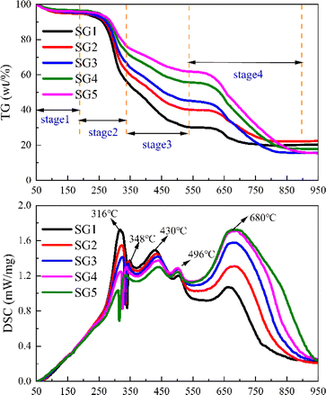
Fig. 1 shows the TG and DSC curves of tobacco stalk blended with different percentages of graphite. In general, the weight loss curves for the samples show similar trends but differ in magnitude, which can be divided into four stages.
 |
| | Fig. 1 TG-DSC curves of the blends without K2CO3. | |
The first stage involves water evaporation around 100 °C, due to prolonged air exposure. The second-stage is the precipitation and combustion of volatile components. When the mixed sample reaches the ignition temperature, the sample rapidly loses weight due to hemicellulose and cellulose combustion, with a sharp exothermic peak at 316 °C.20 Subsequently, a smaller exothermic peak at 348 °C marks the end of volatile combustion, which can be attributed to the carbonization or combustion of lignin.20 Notably, the percentage of weight loss is slightly lower than the VM fraction in the original tobacco stalk, mainly because the mixing of graphite reduces the mass fraction of VM in the tobacco stalk powder. In other words, if the mixing ratio of the VM fraction is considered, the weight loss ratios would align with the VM ratio in the mixed samples. At the same time, the higher the content of tobacco straw, its residual mass after combustion is relatively high, which is because the VM of tobacco straw is higher than that of graphitic carbon.
As the temperature increases, the lignin carbonization ends, and fixed char burns with a smaller exothermic peak at 430 °C. Particularly, a smaller exothermic peak at 496 °C differs from biomass like miscanthus, poplar wood, and rice husk.21 This may be due to the fact that tobacco stalk produced tar during combustion, which hindered some of the coke combustions, resulting in the movement of its combustion toward the high-temperature region.22
The fourth stage involves graphite combustion, with a more intense exothermic peak at 680 °C and sustained combustion due to graphite's higher calorific value. It is worth noting that when referring to our previous work,3 the ignition temperature of graphite in tobacco-graphite carbon mixtures is reduced by about 60 °C from 700 °C to 640 °C, indicating that the combustion of graphite is greatly facilitated due to the presence of tobacco stalk.
Effects of K additives on the co-combustion characteristics
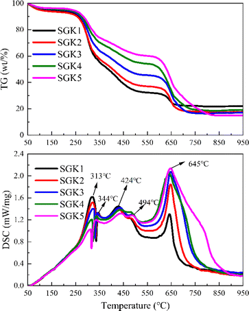
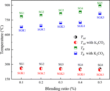
To investigate the effect of K2CO3 on the co-combustion process, Fig. 2 shows the TG and DSC curves of mixtures with K2CO3. When the mixtures are blended with K2CO3, the TG and DSC trends with K2CO3 are similar to those without K2CO3. However, the fourth DSC peak shifts 30 °C lower with K2CO3, and the exothermic peak is higher. For easy understanding, Fig. 3 summarizes the minimum ignition (TMI) and burnout (TB) temperatures with/without K2CO3. It can be easily observed that the TMI is reduced by only 2–7 °C, which shows the slight effect of the K catalyst on the ignition temperature of the mixtures, which is in agreement with the results observed by M. Safar et al.23 This is because the ignition behavior is mainly controlled by the high volatile content of the tobacco stalk. However, the decrease in TB from 76 to 106 °C is due to the presence of K2CO3, which significantly accelerates the combustion of graphite.
 |
| | Fig. 2 TG-DSC curves of the blends with K2CO3. | |
 |
| | Fig. 3 The minimum ignition (TMI) and burnout temperature (TB) of the mixed samples with/without K2CO3. | |
Fig. 4 shows SEM-EDS analysis of elemental distribution, with graphs (d), (g), and (i) representing O, C, and K distribution, respectively. Table 3 lists the detailed surface elemental distribution and corresponding standard deviation. It is easy to notice that the regions of K and O largely coincide with that of C, indicating that the potassium compound has been well mixed with tobacco stalk, and the uniform distribution of C, K and O allows the catalytic combustion process to proceed smoothly. In addition, elements such as Si, Al and Fe were also observed, which can be attributed to some soil attached to the surface of the stalk.24,25 Notably, those elements are involved in reactions leading to ash fouling and slagging in biomass combustors26 and thereby mainly found in ash. Moreover, their weights hardly lose, resulting in fairly high content of ash content of the tobacco stem. Also, Na, Mg, Ca were not clearly observed from the EDS analysis probably due to its low content according to Table 3.
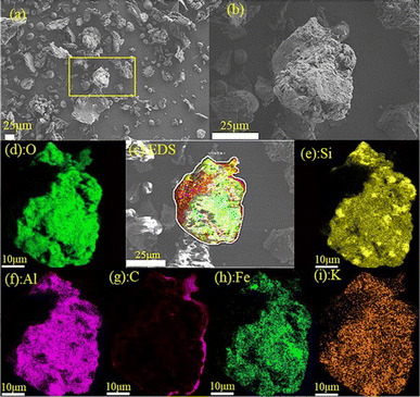 |
| | Fig. 4 SEM and EDS analysis of the mixture (a) SEM overview image; (b) SEM images of the selected particle; (c) EDS face scanning; (d–i) EDS analysis. | |
Table 3 Elemental distribution from EDS analysis
| Element |
C |
O |
Si |
Al |
Fe |
| Wt% |
28.33 |
39.32 |
15.76 |
7.05 |
5.04 |
| Element |
K |
Ca |
Na |
Mg |
Total |
| Wt% |
2 |
0.95 |
0.2 |
1.34 |
100 |
Kinetic analysis for the co-combustion process
To study the different co-combustion behaviors, a kinetic analysis is performed based on the experimental results. According to the methodology proposed by the International Consortium for Thermal Analysis and Calorimetry (ICTAC),27 thermodynamics can be investigated using TG curves based on the assumption of a reaction mechanism function (model-fitting method). To gain insight into the co-combustion process with or without potassium additives, the mechanism function f(α) in eqn (1) is used to describe the weight loss process of the mixed samples. n = 1, 2, 3 correspond to the first-, second-, and third-order (Avrami–Erofeev equations28) mechanism functions.| |
 | (2) |
where α is the conversion ratio of the graphite and n stands for the order of the reaction; W0, Wt and W∞ respectively represents the sample weight at the initial time, time t and the termination time, g.
For slowly heating combustion processes, the reaction rate is controlled by chemical kinetics, and the relationship between reaction rate and temperature follows Arrhenius's law in eqn (3). Eqn (3) was then processed using the Coats–Redfern method29 to obtain eqn (4) for data fitting, where G(α) is determined by integrating the formula in eqn (5). The values of −(E/R) and ln(AR/βE) are derived from the slope and intercept of the linear regression line of ln(G(α)/T2) on 1/T.
The values of −(E/R) and ln(AR/βE) are derived from the slope and intercept of the linear regression line of ln(G(α)/T2) on 1/TG(α) of −ln(1 − α), α/(1 − α), and (2α − α2)/2(1 − α)2, respectively, correspond to kinetic models for n = 1, 2 and 3, and are generally used to describe the combustion of coal or biomass.
| |
 | (3) |
| |
 | (4) |
| |
 | (5) |
where
A is the pre-exponential factor, min
−1;
β is the heating rate, 10 K min
−1;
E is the activation energy, kJ mol
−1;
R is the universal gas constant, 8.314 × 10
−3 kJ mol
−1 K
−1;
T is the temperature in Kelvin.
Based on the TG curves, the heat loss process of the mixture is divided into three main stages: volatile fraction combustion, fixed carbon combustion, and graphite carbon combustion. Due to the three-step nature of decomposition, it seems not possible to use the same kinetic parameters to describe normal degradation over the entire temperature range accurately, and each stage is analyzed kinetically separately here.30 Tables 4–6 summarizes the results of the linear regression at different stages. Fig. 5 and 6 shows the linear regression curves. The results show that the combustion in the first stage conforms to the first-order kinetic model with an R2 value greater than 0.985. The combustion in the second and third stages conforms to the third-order kinetic model.
Table 4 The first-stage kinetic parameters
| Samples |
R2 (n = 1) |
E (kJ mol−1) |
A (min−1) |
Regression equations |
| SG1 |
0.993 |
69.8 |
1.90 × 10⁵ |
y = −8407.2x + 0.829 |
| SG2 |
0.993 |
63.9 |
3.99 × 10⁴ |
y = −7691.6x − 0.656 |
| SG3 |
0.989 |
57.2 |
7.30 × 10³ |
y = −6878.3x − 2.243 |
| SG4 |
0.992 |
56.9 |
5.34 × 10³ |
y = −6842.2x − 2.550 |
| SG5 |
0.985 |
45.5 |
3.28 × 10² |
y = −5469.6x − 5.118 |
| SGK1 |
0.995 |
61.7 |
2.80 × 10⁴ |
y = −7417.6x − 0.975 |
| SGK2 |
0.994 |
54.5 |
5.34 × 10³ |
y = −6551.4x − 2.507 |
| SGK3 |
0.991 |
53.8 |
3.56 × 10³ |
y = −6473.9x − 2.900 |
| SGK4 |
0.991 |
44.2 |
3.11 × 10² |
y = −5315.0x − 5.143 |
| SGK5 |
0.991 |
40.8 |
1.18 × 10² |
y = −4909.3x − 6.030 |
Table 5 The second-stage kinetic parameters
| Samples |
R2 (n = 3) |
E (kJ mol−1) |
A (min−1) |
Regression equations |
| SG1 |
0.991 |
23.4 |
7.97 |
y = −2814.2x − 8.169 |
| SG2 |
0.986 |
15.7 |
8.82 × 10⁻¹ |
y = −1888.6x − 9.972 |
| SG3 |
0.988 |
13.9 |
4.43 × 10⁻¹ |
y = −1671.1x − 10.54 |
| SG4 |
0.968 |
9.70 |
9.48 × 10⁻² |
y = −1164.2x − 11.72 |
| SG5 |
0.967 |
6.50 |
2.78 × 10⁻² |
y = −780.98x − 12.55 |
| SGK1 |
0.991 |
23.2 |
6.82 |
y = −2784.6x − 8.315 |
| SGK2 |
0.993 |
18.8 |
2.14 |
y = −2263.7x − 9.268 |
| SGK3 |
0.992 |
14.3 |
4.94 × 10⁻¹ |
y = −1724.1x − 10.46 |
| SGK4 |
0.995 |
10.5 |
1.24 × 10⁻¹ |
y = −1261.7x − 11.53 |
| SGK5 |
0.986 |
7.50 |
4.12 × 10⁻² |
y = −906.96x − 12.30 |
Table 6 The third-stage kinetic parameters
| Samples |
R2 (n = 3) |
E (kJ mol−1) |
A (min−1) |
Regression equations |
| SG1 |
0.945 |
41.0 |
8.13 × 101 |
y = −4925.8x − 6.406 |
| SG2 |
0.995 |
43.6 |
6.18 × 101 |
y = −5242.5x − 6.743 |
| SG3 |
0.994 |
73.6 |
4.83 × 10³ |
y = −8857.8x − 2.910 |
| SG4 |
0.989 |
74.2 |
3.16 × 10³ |
y = −8922.5x − 3.342 |
| SG5 |
0.990 |
78.5 |
4.38 × 10³ |
y = −9438.3x − 3.071 |
| SGK1 |
0.950 |
75.0 |
1.35 × 10⁴ |
y = −9018.2x − 1.899 |
| SGK2 |
0.937 |
128.2 |
2.26 × 10⁷ |
y = −15398x + 4.988 |
| SGK3 |
0.980 |
132 |
2.55 × 10⁷ |
y = −15862x + 5.080 |
| SGK4 |
0.980 |
112.1 |
1.21 × 10⁶ |
y = −13428x + 2.200 |
| SGK5 |
0.989 |
99.3 |
1.39 × 10⁵ |
y = −11942x + 0.150 |
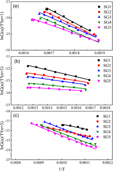 |
| | Fig. 5 Linear regression curves without K2CO3 (a) the first-stage (<350 °C); (b) the second-stage (350–650 °C); (c) the third-stage. | |
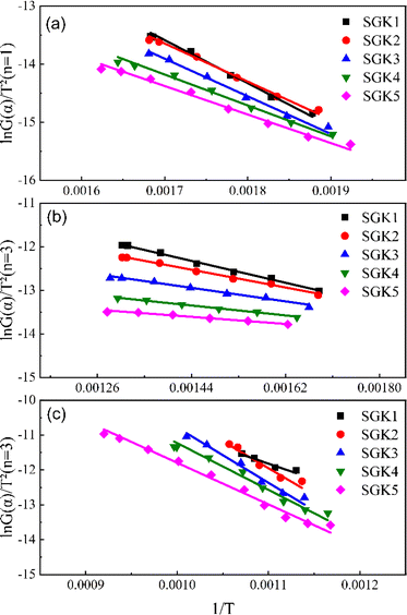 |
| | Fig. 6 Linear regression curves with K2CO3 (a) the first-stage (<350 °C); (b) the second-stage (350–650 °C); (c) the third-stage. | |
According to the activation energies in Table 4, it can be known that the activation energy of the first stage of the co-pyrolysis process decreases by 3.4–12.7 kJ mol−1 after the addition of K2CO3, and the activation energy decreases the most at the ratio of graphite to tobacco stalk of 0.67 (40![[thin space (1/6-em)]](https://www.rsc.org/images/entities/char_2009.gif) :
:![[thin space (1/6-em)]](https://www.rsc.org/images/entities/char_2009.gif) 60), while there is no decrease in the activation energy of the second and third-stages. In the initial stage of the combustion, the activation energy decreases with the increase of graphite content mainly because the electrical conductivity and thermal conductivity of graphite play a role in enhancing electron transfer and accelerating the reaction during the co-combustion process. In addition, the interaction between graphite and biomass changes the pyrolysis behavior of the fuel, which reduces the heat required for thermally resolving volatiles and pyrolysis of its lignin, resulting in a decrease in activation energy. According to the pre-exponential factor, the pre-exponential factor of the third stage becomes significantly larger after the addition of K2CO3, which indicates that the addition of K could make the combustion of the graphite carbon stage more intense, which is in line with what the DSC curves exhibited. However, when the ratio of graphite carbon to tobacco stalks reaches 0.43 (30
60), while there is no decrease in the activation energy of the second and third-stages. In the initial stage of the combustion, the activation energy decreases with the increase of graphite content mainly because the electrical conductivity and thermal conductivity of graphite play a role in enhancing electron transfer and accelerating the reaction during the co-combustion process. In addition, the interaction between graphite and biomass changes the pyrolysis behavior of the fuel, which reduces the heat required for thermally resolving volatiles and pyrolysis of its lignin, resulting in a decrease in activation energy. According to the pre-exponential factor, the pre-exponential factor of the third stage becomes significantly larger after the addition of K2CO3, which indicates that the addition of K could make the combustion of the graphite carbon stage more intense, which is in line with what the DSC curves exhibited. However, when the ratio of graphite carbon to tobacco stalks reaches 0.43 (30![[thin space (1/6-em)]](https://www.rsc.org/images/entities/char_2009.gif) :
:![[thin space (1/6-em)]](https://www.rsc.org/images/entities/char_2009.gif) 70), the pre-exponential coefficient becomes smaller, which suggests that there is an optimal ratio of 0.43 for co-combustion behavior.
70), the pre-exponential coefficient becomes smaller, which suggests that there is an optimal ratio of 0.43 for co-combustion behavior.
Conclusions
In this paper, the effect of potassium catalyst on the combustion characteristics of blends of tobacco stalk and graphite carbon was investigated, and the main conclusions obtained are as follows: (1) the minimum ignition temperature of the blend is mainly controlled by tobacco stalk, while the burnout temperature is mainly controlled by graphite carbon; (2) the catalyst K2CO3 can significantly reduce the burnout temperature of the blend, up to 106 °C. Meanwhile, since the ignition temperature of tobacco stalk is already very low, K2CO3 has minimal effect on the lowest ignition temperature of the blend. (3) Kinetic analyses showed that weight loss in the first-stage of the blend conformed to a first-order kinetic model, while the second and third-stages conformed to a third-order kinetic model. Meanwhile, the addition of K2CO3 can make the combustion of graphite carbon stage more intense.
Data availability
The data supporting the findings of this study are available from the corresponding author upon reasonable request. The datasets generated and/or analyzed during the current study, including thermogravimetric analysis (TG-DSC) data, scanning electron microscopy with energy-dispersive spectroscopy (SEM-EDS) results, and experimental results on co-combustion characteristics, are not publicly available due to privacy concerns. However, interested researchers can contact the corresponding author [E-mail: wangzean@whpu.edu.cn] to request access to the data.
Author contributions
Zean Wang: writing – review & editing & formal analysis; Jianjun Yang: writing – original draft; Yu Zhai: investigation; Jibin Chen: resources & funding acquisition; Houchang Pei: methodology & data curation; Liangbo Sun: conceptualization & project administration; Hao Liu: supervision.
Conflicts of interest
The authors declare that they have no known competing financial interests or personal relationships that could have appeared to influence the work reported in this paper.
Acknowledgements
The authors acknowledge the financial support from the Scientific Research Foundation of Wuhan Polytechnic University.
Notes and references
- A. A. Ruprecht, C. De Marco, A. Saffari, P. Pozzi, R. Mazza, C. Veronese, G. Angellotti, E. Munarini, A. C. Ogliari, D. Westerdahl, S. Hasheminassab, M. M. Shafer, J. J. Schauer, J. Repace, C. Sioutas and R. Boffi, Aerosol Sci. Technol., 2017, 51, 674–684 CrossRef.
- E. Simonavicius, A. McNeill, L. Shahab and L. S. Brose, Tob. Control, 2019, 28, 582–594 CrossRef PubMed.
- C. Luo, D. Li, L. Huang, Z. Wang, J. Zhang, H. Liu and Z. Liu, RSC Adv., 2021, 11, 1662–1667 RSC.
- C. Luo, L. Huang, Y. Chen, Z. Wang, H. Ren, H. Liu and Z. Liu, RSC Adv., 2022, 12, 3431–3436 RSC.
- J. Bai, H. Gao, J. Xu, L. Li, P. Zheng, P. Li, J. Song, C. Chang and S. Pang, Energy, 2022, 242, 122535 CrossRef CAS.
- M. Banožić, J. Babić and S. Jokić, Ind. Crops Prod., 2020, 144, 112009 CrossRef.
- H. Gao, J. Bai, Y. Wei, W. Chen, L. Li, G. Huang, P. Li and C. Chang, Biomass Convers. Biorefin., 2022, 13, 11521–11531 CrossRef.
- C. Ma, F. Zhang, H. Liu, J. Hu, S. Yang and H. Wang, Fuel, 2023, 350, 128902 CrossRef CAS.
- Y. Lin, C. Wang, G. Yu, H. Wang, R. Liang, F. Kong and D. Song, Biomass Convers. Biorefin., 2024, 14(19), 11697–11705 CrossRef CAS.
- Q. Xia, B. Yan, H. Wang, J. Xu, S. Zhang, G. Zhou, A. Hu, J. Jiang, S. Xu, J. Wang and W. Chen, Biomass Convers. Biorefin., 2020, 11, 1611–1619 CrossRef.
- J. Cai, B. Li, C. Chen, J. Wang, M. Zhao and K. Zhang, Bioresour. Technol., 2016, 220, 305–311 CrossRef CAS.
- J. Bai, L. Li, Z. Chen, C. Chang, S. Pang and P. Li, Energy, 2023, 281, 128283 CrossRef CAS.
- M. B. Santana, L. B. Soares, E. Zanella, M. Fellipe da Silva, B. U. Stambuk, R. Goldbeck, A. Ambrosi, A. Zielinski, P. Poletto and J. L. Ienczak, Bioresour. Technol., 2023, 382, 129169 CrossRef CAS.
- C. Hadey, M. Allouch, I. Loulidi, A. Kali, F. Z. Zouhair, A. A. Alrashdi, A. Amar, M. Jabri, M. Alami, H. Lgaz and F. Boukhlifi, Biomass Convers. Biorefin., 2024, 1–11 Search PubMed.
- X. G. Li, Y. Lv, B. G. Ma, S. W. Jian and H. B. Tan, Bioresour. Technol., 2011, 102, 9783–9787 CrossRef CAS.
- K. Zhang, K. Zhang, Y. Cao and W. P. Pan, Bioresour. Technol., 2013, 131, 325–332 CrossRef CAS PubMed.
- K. Cong, F. Han, Y. Zhang and Q. Li, Fuel, 2019, 237, 126–132 CrossRef CAS.
- A. Toptas, Y. Yildirim, G. Duman and J. Yanik, Bioresour. Technol., 2015, 177, 328–336 CrossRef CAS PubMed.
- J. Parikh, S. A. Channiwala and G. K. Ghosal, Fuel, 2007, 86, 1710–1719 CrossRef CAS.
- J.-J. Lu and W.-H. Chen, Appl. Energy, 2015, 160, 49–57 CrossRef.
- M. V. Kok and E. Özgür, Fuel Process. Technol., 2013, 106, 739–743 CrossRef CAS.
- Q. Yang, T. Wang, J. Wang, Z. Sui, L. Wang, Y. Zhang and W.-P. Pan, Thermochim. Acta, 2021, 702, 178979 CrossRef CAS.
- M. Safar, B.-J. Lin, W.-H. Chen, D. Langauer, J.-S. Chang, H. Raclavska, A. Pétrissans, P. Rousset and M. Pétrissans, Appl. Energy, 2019, 235, 346–355 CrossRef CAS.
- E. Pučko, G. Žibret and K. Teran, J. Geochem. Explor., 2024, 258, 107422 CrossRef.
- B. Yuan, F. Luo, J. Wang, G. Ji, Y. Xie, D. Shao, X. Li, D. Liu and X. Lu, J. Environ. Chem. Eng., 2023, 11(3), 109751 CrossRef CAS.
- A. Demirbas, Energy Sources, Part A, 2007, 29, 549–561 CrossRef CAS.
- S. Vyazovkin, A. K. Burnham, J. M. Criado, L. A. Pérez-Maqueda, C. Popescu and N. Sbirrazzuoli, Thermochim. Acta, 2011, 520, 1–19 CrossRef CAS.
- X. Liu, M. Chen and Y. Wei, Fuel, 2015, 143, 577–585 CrossRef CAS.
- A. W. Coats and J. P. Redfern, Nature, 1964, 201, 68–69 CrossRef CAS.
- P. Parthasarathy, K. S. Narayanan and L. Arockiam, Biomass Bioenergy, 2013, 58, 58–66 CrossRef CAS.
|
| This journal is © The Royal Society of Chemistry 2024 |
Click here to see how this site uses Cookies. View our privacy policy here.  Open Access Article
 *ab,
Jianjun Yanga,
Yu Zhaia,
Jibin Chena,
Houchang Peia,
Liangbo Suna and
Hao Liub


![[thin space (1/6-em)]](https://www.rsc.org/images/entities/char_2009.gif) :
:![[thin space (1/6-em)]](https://www.rsc.org/images/entities/char_2009.gif) 60), while there is no decrease in the activation energy of the second and third-stages. In the initial stage of the combustion, the activation energy decreases with the increase of graphite content mainly because the electrical conductivity and thermal conductivity of graphite play a role in enhancing electron transfer and accelerating the reaction during the co-combustion process. In addition, the interaction between graphite and biomass changes the pyrolysis behavior of the fuel, which reduces the heat required for thermally resolving volatiles and pyrolysis of its lignin, resulting in a decrease in activation energy. According to the pre-exponential factor, the pre-exponential factor of the third stage becomes significantly larger after the addition of K2CO3, which indicates that the addition of K could make the combustion of the graphite carbon stage more intense, which is in line with what the DSC curves exhibited. However, when the ratio of graphite carbon to tobacco stalks reaches 0.43 (30
60), while there is no decrease in the activation energy of the second and third-stages. In the initial stage of the combustion, the activation energy decreases with the increase of graphite content mainly because the electrical conductivity and thermal conductivity of graphite play a role in enhancing electron transfer and accelerating the reaction during the co-combustion process. In addition, the interaction between graphite and biomass changes the pyrolysis behavior of the fuel, which reduces the heat required for thermally resolving volatiles and pyrolysis of its lignin, resulting in a decrease in activation energy. According to the pre-exponential factor, the pre-exponential factor of the third stage becomes significantly larger after the addition of K2CO3, which indicates that the addition of K could make the combustion of the graphite carbon stage more intense, which is in line with what the DSC curves exhibited. However, when the ratio of graphite carbon to tobacco stalks reaches 0.43 (30![[thin space (1/6-em)]](https://www.rsc.org/images/entities/char_2009.gif) :
:![[thin space (1/6-em)]](https://www.rsc.org/images/entities/char_2009.gif) 70), the pre-exponential coefficient becomes smaller, which suggests that there is an optimal ratio of 0.43 for co-combustion behavior.
70), the pre-exponential coefficient becomes smaller, which suggests that there is an optimal ratio of 0.43 for co-combustion behavior.

