 Open Access Article
Supramolecular architecture of theophylline polymorphs, monohydrate and co-crystals with iodine: study from the energetic viewpoint†
Irina S. Konovalova *ab,
Svitlana V. Shishkinabc,
Maik Wyshuseka,
Michael Patzerd and
Guido J. Reissa
aInstitut für Bioanorganische Chemie Heinrich-Heine-Universität Dusseldorf, Universitätsstrasse 1, 40225 Düsseldorf, Germany
bSSI “Institute for Single Crystals”, National Academy of Science of Ukraine, 60 Nauky Ave., Kharkiv 61001, Ukraine
cInstitute of Organic Chemistry, National Academy of Sciences of Ukraine, Akademika Kukharya Street 5, Kyiv, 02094, Ukraine
dMax-Planck-Institut für Kohlenforschung, Kaiser-Wilhelm-Platz 1, 45470 Mülheim an der Ruhr, Germany
First published on 18th September 2024
Abstract
The regularities of crystal structure organization were thoroughly studied in all to date known polymorphic modifications of theophylline (THP) using an energetic approach. The monohydrate and a co-crystal of theophylline with one half equivalent of an iodine molecule were similarly investigated. The calculations of pairwise interaction energies have showed that the crystals studied can be divided into two groups according to their basic structural motifs: columnar-layered or columnar. The energetic approach also allows the role of different interactions in the crystal structure formation to be estimated. It was found that strong N–H⋯N, N–H⋯O hydrogen bonds and stacking interactions play the most important roles in polymorphic modifications of THP and the THP monohydrate. In the case of the co-crystal with iodine, N–H⋯O hydrogen bond participates in the dimeric building unit formation. However, instead of a stacking interaction the π⋯π interaction between carbonyl groups of neighboring molecules plays the highest role in the supramolecular architecture of this crystal. The lattice energies calculations in periodic conditions for polymorphic structures have shown that polymorph with the most anisotropic energetic structure may be considered as stable and all others forms metastable. In the polymorphic modification 1 of THP a zwitter-ionic resonance form is predominant, which affects significantly the solubility and the intermolecular interactions of this modification.
Introduction
The creation of new and tailored functional materials is an important aim of modern chemical science. Each functional material has unique properties, which makes it an attractive basis for the design of new materials in which the properties of the final product are determined by the chemical assembly of the molecules that form it.1 A detailed study of solids by physicochemical methods often leads to the discovery of various crystalline forms especially for many well-known organic compounds. This can be attributed to the fact that functional groups are capable of forming strong and weak intermolecular interactions. Variety is often favoured by the presence in the molecule a number of proton donors and proton acceptors. In most cases, polymorphic modifications of an organic compound can exhibit significantly different physicochemical and pharmacological properties.2,3 For this reason, an understanding of the phenomenon of polymorphism for a compound is of utmost interest for the chemical and pharmaceutical industry.4The natural product theophylline (systematic name: 1,3-dimethyl-3,7-dihydro-1H-purine-2,6-dione) has been known for more than 100 years.5,6 Albrecht Kossel first isolated theophylline in 1888 from an extract of the leaves of the tea plant, from which its trivial name derives. Even to the present day there remains interest in this compound and its solid state phases7 as well as its medical applications.8 Theophylline is used as pharmaceutical agent due to its effects on the respiratory system.9–12 Its crystal modifications are of interest because of their number in spite of the fact that the theophylline molecule is conformationally rigid. According to a search in the Cambridge Structural Database (CSD)13 five modifications are listed so far (Table 2). The conformational rigidity of the theophylline molecule suggests that the polymorphic modifications are solely a consequence of various arrangements of intermolecular interactions. In addition, several structure determinations of the monohydrate of theophylline have been deposited with the CSD, and all face minor structural problems.7,14–16 An attempt to solve the structural problems of the monohydrate of theophylline seems not to be plausible.17 A number of co-crystals of neutral theophylline18–21 and theophyllinium salts22 have been synthesized in order to modify the pharmacological and technological properties of the substance. Theophylline monohydrate and co-crystal with I2 were synthesized for this study.
In general, the biological and pharmacological activity of any organic substance is the result of a number of factors. The ability of the solid to be assimilated in the digestive tract is one of the determining factors. It can be expected that destruction of the crystal structure, which is the first stage of such assimilation, should depend on the nature of the intermolecular interactions, and hence the interaction energy of molecules in the crystal. All modern approaches to the analysis of a crystal structure are based on a comparison of the geometric characteristics of intermolecular interactions and often take into account only strong classic interactions.23–28 However, these approaches can be misleading, because they are roughly descriptive and do not provide any information about the energy of molecular interactions. We have shown that often weak interactions are key features that lead to the formation of polymorphic modifications. These interactions are difficult to identify and evaluate by spectral methods.29–31 In our view, the true reasons for the formation of polymorphic modifications are often missed.
It has been shown that analysing the energy of intermolecular interactions in crystals by quantum chemical methods provides detailed information about the interactions between molecules.32–34 Quantum chemical methods can therefore aid in understanding the factors affecting the possibility of the formation of polymorphic modifications. The energy approach is justified since the crystal structures of theophylline, its monohydrate and co-crystal with the iodine molecule contain strong classical hydrogen bonds, stacking interactions and weak interactions such as C–H⋯O, C–H⋯π and halogen interactions. It should be noted that despite their low strengths, weak intermolecular interactions can play key role in the crystal formation, especially if they are dominant.35–37
To the best of our knowledge there is no systematic structural comparison of all five known modifications of theophylline, its monohydrate and its co-crystal with an iodine molecule. This contribution is the first attempt to provide a complete structural analysis on these compounds from an energy point of view. In the present study we report a systematic analysis of intermolecular interactions in the aforementioned crystals and investigate what role they play in the supramolecular architecture and which forces are involved.
Experimental section
Quantum chemical calculations
All polymorphic modifications of theophylline (THP) were retrieved from the Cambridge Structural Database (release 2023).13 Since several atom types were incorrectly assigned in the structure with the CSD refcode BAPLOT09 (Table 2), we re-refined the structure using the deposited intensity diffraction data and used our refinement results here. The analysis of the supramolecular architecture of the crystals was performed using the energetic approach that was suggested earlier.32–34 The first coordination sphere for each molecule in the asymmetric unit (M0) was determined using the standard procedure within the Mercury program (version 4.2)38 as had been suggested previously.22 The cluster so obtained was divided into dimers where the central molecule is assigned to be M0 and other molecule Mi belongs to its first coordination sphere. The positions of the hydrogen atoms were normalized to 1.089 Å for C–H and 1.015 Å for N–H bonds according to the results of the geometry optimization of the isolated molecule. Normalization of the hydrogen atoms positions is necessary because the X–H bonds determined by X-ray diffraction study are artificially shortened.39The interaction energies between molecules within each of M0–Mi dimers were calculated using the density functional theory with a B97-D3 functional and a Def2-TZVP basis set40–44 and corrected for basis set superposition error by the counterpoise method.45 The B97-D3 functional has been benchmarked to be the most reliable dispersion-corrected density functional for calculations of intermolecular interactions.46 All the calculations were performed with ORCA 3.0 software.47
The analysis of the pairwise interaction energies is based on an assumption that the calculated values take on vector properties32 because each calculated interaction energy originates from the geometric center of the basic molecule M0 and is directed to one of the neighbouring molecules Mi. All the energy vector lengths within the first coordination sphere of the basic molecule are normalized to the strongest pairwise interaction energy using the equation:
| Li = (RiEi)/2Estr |
Such a normalization ensures independence of the vector lengths from the calculation method. Application of this approach makes it possible to replace the basic molecule by its vector image and to construct the energy-vector diagram of a crystal using symmetry operations.
The topological analysis of theoretical electron density distribution was performed using the AIMAll program48 with all default options. Electron density was calculated with M062X/def2TZVP derived wavefunction.
The calculations of the lattice energies were performed in periodic boundary conditions using the CRYSTAL17 program.49,50 The calculations were based on Kohn–Sham density functional theory.51 B3LYP, the popular combination of Be88 and LYP, was used as the functional.52,53 For the treatment of dispersion interactions, the dispersion correction D3(BJ) was used.54–56 To correct the basis set superposition error (BSSE), the automatic general counterpoise correction implemented in CRYSTAL17 was used.57,58 The POB-TZVP basis set stored in the program was used.59 The SHRINK factor was set to eight. For the calculation of the energies, the fractional coordinates of the atoms were pre-optimized. The cell parameters were fixed to the values obtained in the experiment.
Space group revision and redetermination of the crystal structure of theophylline monohydrate (structure 6)
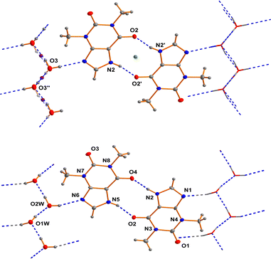
As far back as 1958 Sutor15 reported the crystal structure of theophylline monohydrate. The asymmetric unit found in this study contains two theophylline molecules and two water molecules in general positions in the space group P21. This early structure determination faced a slight problem with the location of methyl hydrogen atoms. The basic structural feature of this structure are dimers of two crystallographically independent theophylline molecules that are attached on both sides by chains of hydrogen bonded water molecules to form a layered structure (see Fig. 1).In the years between 2002 and 2020 several groups re-determined the structure of theophylline monohydrate at various temperatures7 and even a neutron diffraction study7 was undertaken. In all these studies almost the same unit cell parameters were obtained and the structure of the theophylline monohydrate was assigned to the space group P21/n with one theophylline molecule and one water molecule in the asymmetric unit. The structure is roughly the same as the historically structural model in the space group P21. But the single theophylline molecule forms a N–H⋯O hydrogen bonded dimer about an inversion centre (green dot in the upper part of Fig. 1) that is connected to water molecules arranged in a chain. All these structural models exhibit a disorder within the hydrogen bonded water chains as a consequence of the inversion centres within the chain (violet dots in the upper part of Fig. 1) belonging to the symmetry elements of the space group P21/n.
In the case of a possible pseudosymmetry problem which may affect the selection of the true space group, it is useful to identify the symmetry elements that cause the disorder.60a In the case of theophylline monohydrate the water molecules show a polar connectivity in their chains. The structural model using the space group P21/n require inversion centres in these polar chains (violet dots in the upper part of the figure). Consequently the proposed inversion symmetry within the chains7 restricts the ratio of the “up”-chains to “down”-chains to 1/1 within each domain of the crystal. This structural model is not plausible in our view, and thus seems to be the reason for some problems that were faced in the previous investigations. It should be borne in mind that a theoretical study17 suggests that the space group assignment of P21/n may be wrong. But in this investigation it was wrongly assumed that the only sub group of P21/n would be Pn. According to the generally accepted theory of group-sub group relationships,60b several space groups have to be considered in the case of P21/n. Thus, the direct sub groups of P21/n that do not feature an inversion centre are P21 and Pn. We performed test refinements for both non-centrosymmetric cases (based on our own dataset with a good resolution at low temperature) and obtained fully ordered models in both cases. In the case of our low temperature dataset, the structural model based on P21 fits the data much better than Pn (see Table 1). The relatively large differences of the wR2 factors between the two hypotheses confirms our space group assignment. The scattering power of one hydrogen atom would not cause these differences. The whole structure refinement including displacement parameters converges in the correct space group. Thus, we were able to refine a completely ordered structural model in the space group P21.
| Space group | P21 | Pn | P21/n |
| Cell | a = 4.46150(10) Å; b = 15.3156(3) Å; c = 13.0669(3) Å; β = 97.558(2)° | ||
| Refl. (unique) | 6403 | 6292 | 3201 |
| No. of parameters | 275 | 275 | 144 |
| wR2 (all reflections) | 0.0926 | 0.1036 | 0.1258 |
| R1 (I > 2σ(I)) | 0.0407 | 0.0447 | 0.0500 |
| Diff. density | 0.49/−0.23 e Å−3 | 0.47/−0.28 e Å−3 | 0.45/−0.26 e Å−3 |
| GooF for all reflections | 1.009 | 1.002 | 1.019 |
Redetermination of a monoclinic modification of theophylline
While analysing the different polymorphs of theophylline that are deposited in the Cambridge Structural Database (CSD) we observed that the entry BAPLOT09 (space group Pn, T = 290 K, 1) had been corrected by the CSD. Two of the nitrogen atom positions of theophylline were refined as carbon atoms in the original deposition. Fortunately, the original diffraction data were deposited and we were able to do a re-refinement with the correct atom type assignment. As expected the R factors dropped significantly by the replacement. All subsequent calculations are based on the newly refined structure.The crystal structure of 7 [theophylline–iodine (2/1)]
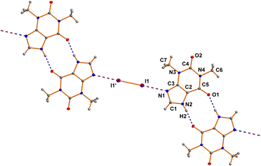
The asymmetric unit of 7 comprises one THP molecule and one half of a I2 molecule. The I2 molecule is arranged around an inversion center (see Fig. 2). The neutral THP molecule forms a dimeric unit with a neighboring THP molecule via two classical N–H⋯O hydrogen bonds around an inversion center in the space group P21/c. Bond lengths and angles are all in the expected ranges.15 The same is true for the N⋯I and I–I distances of 2.8879(17) Å and 2.7088(3) Å, respectively.60cResults and discussion
A search in the Cambridge Structural Database13 reveals the crystal structures of five polymorphic forms of the theophylline. As can be seen from Table 2 most of the known polymorphs crystallize in non-centrosymmetric space groups.7,61 Only two of them, as well as the co-crystal with iodine, crystallized in centrosymmetric P21/c space group.62,63| No. | Refcode | Space group | T, K | a, Å | b, Å | c, Å | β, deg | V, Å3 | Density, g cm−3 | Ref. |
|---|---|---|---|---|---|---|---|---|---|---|
| a The supplementary crystallographic data for this paper are deposited with the Cambridge Crystallographic Data Centre (CCDC). These data can be obtained free of charge from the Cambridge Crystallographic Data Centre via http://www.ccdc.cam.ac.uk/structures. CCDC numbers: (THEO)2·I2: 2323508; THEO·H2O: 2264675 BAPLOT09: 2264834. | ||||||||||
| 1 | BAPLOT09 | Pn | 290 | 3.8744(4) | 12.8898(9) | 8.1167(6) | 98.965(8) | 400.4 | 1.494 | 61a |
| 2 | BAPLOT05 | Pna21 | 120 | 13.087(2) | 15.579(3) | 3.8629(6) | 90 | 787.6 | 1.519 | 7 |
| 3 | BAPLOT06 | Pna21 | 120 | 24.330(1) | 3.7707(2) | 8.4850(5) | 90 | 778.4 | 1.537 | 7 |
| 4 | BAPLOT08 | P21/c | 298 | 4.5310(7) | 11.5783(1) | 15.7188(2) | 93.69(1) | 822.9 | 1.454 | 62 |
| 5 | BAPLOT03 | P21/c | 100 | 7.7055(1) | 13.0010(2) | 15.7794(3) | 103.224(1) | 1538.8 | 1.555 | 63 |
| 6 | THEO·H2O | P21 | 115 | 4.4615(1) | 15.3156(3) | 13.0669(3) | 97.558(2) | 885.1 | 1.487 | a |
| 7 | (THEO)2·I2 | P21/c | 100 | 6.0794(1) | 16.9054(3) | 9.2013(2) | 99.973(2) | 931.4 | 2.190 | a |
Molecular structure analysis
The molecular and crystal structures of five theophylline (THP) polymorphic forms have been published so far.7,61–63 Form I (CSD refcode BAPLOT05)7 is the high-temperature polymorph, which is reported to be the most stable form above 232 °C. Form II (BAPLOT06)7 is more stable at room temperature. Form IV (BAPLOT03)63 is hitherto the most stable (known) polymorph. The monohydrate form (THEOPH01)14 is the most stable at high humidity and low temperature, but it is efflorescent and slowly starts to dehydrate under standard conditions. The dehydration process produces a mixture of the stable and metastable forms, which is problematical from a pharmaceutical point of view.The THP molecule is a xanthine, formally consisting of a fused pyrimidinedione and imidazole moiety. The theophylline is amphiphilic in hydrogen bonding because of its ability to accept protons at N2 and to donate protons from N1. The ability of N2 to accept proton and the presence of proton migration channels (keto–enol tautomerism) makes this naturally basic compound weakly acidic. As a result, three tautomers can exist if one excludes zwitterionic forms (Fig. 4). According to the results of quantum-chemical calculations the most stable tautomer is A. Due to the position of the amine hydrogen atom adjacent to carbonyl group, only this tautomer can form the energetically favorable centrosymmetrical N–H⋯O dimer. It is worth noting that tautomer A is observed in the crystals of THP (Fig. 4).
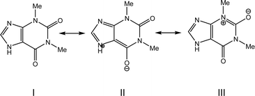
An analysis of molecular structures reveals that, except for structure 3, the carbonyl bonds are not equivalent in the THP molecules found in the different polymorphic structures (Table 3). There are three possible reasons of such differences: the contribution of the zwitterionic resonance forms to the molecular structure of THP (Scheme 1), the different participation of two carbonyl groups in intermolecular hydrogen bonds or the strong polarization of the molecule by a polar environment in the crystalline phase.
| Bond | 1 | 2 | 3 | 4 | 5 | 6 | 7 | ||
|---|---|---|---|---|---|---|---|---|---|
| A | B | A | B | ||||||
| O1–C7 | 1.230(6) | 1.226(4) | 1.226(2) | 1.2552 | 1.239(3) | 1.239(3) | 1.238(4) | 1.236(4) | 1.239(3) |
| O2–C6 | 1.205(7) | 1.233(5) | 1.222(2) | 1.2416 | 1.222(2) | 1.221(2) | 1.224(4) | 1.223(3) | 1.223(3) |
| N1–C1 | 1.332(7) | 1.343(6) | 1.340(2) | 1.3532 | 1.346(3) | 1.341(3) | 1.351(5) | 1.339(5) | 1.340(3) |
| N1–C2 | 1.386(5) | 1.376(5) | 1.380(2) | 1.3797 | 1.384(2) | 1.386(2) | 1.376(4) | 1.383(3) | 1.380(4) |
| N2–C1 | 1.337(7) | 1.340(5) | 1.338(2) | 1.3485 | 1.338(3) | 1.335(3) | 1.348(5) | 1.335(5) | 1.340(3) |
| N2–C3 | 1.352(6) | 1.360(6) | 1.356(2) | 1.3621 | 1.362(3) | 1.363(3) | 1.344(4) | 1.375(3) | 1.357(3) |
| N3–C5 | 1.494(7) | 1.469(6) | 1.473(3) | 1.4653 | 1.473(3) | 1.471(3) | 1.460(4) | 1.485(4) | 1.469(4) |
| N3–C6 | 1.398(7) | 1.386(5) | 1.411(2) | 1.4052 | 1.398(3) | 1.401(3) | 1.410(4) | 1.399(4) | 1.406(3) |
| N3–C7 | 1.409(7) | 1.422(4) | 1.405(2) | 1.4081 | 1.408(3) | 1.407(3) | 1.406(4) | 1.392(4) | 1.395(4) |
| N4–C3 | 1.380(6) | 1.382(5) | 1.370(2) | 1.3707 | 1.380(3) | 1.373(3) | 1.381(4) | 1.364(4) | 1.376(3) |
| N4–C4 | 1.465(7) | 1.467(5) | 1.465(2) | 1.4593 | 1.460(3) | 1.465(3) | 1.475(4) | 1.451(5) | 1.467(3) |
| N4–C6 | 1.379(6) | 1.364(6) | 1.382(2) | 1.389 | 1.378(3) | 1.384(3) | 1.364(4) | 1.389(4) | 1.377(3) |
| C2–C3 | 1.346(7) | 1.362(6) | 1.375(2) | 1.3885 | 1.369(3) | 1.368(3) | 1.381(4) | 1.368(4) | 1.376(3) |
| C2–C7 | 1.420(7) | 1.416(4) | 1.429(2) | 1.415 | 1.415(3) | 1.416(3) | 1.413(4) | 1.422(4) | 1.416(4) |
The electron distribution within the THP molecule can be described as a superposition of three resonance structures (I–III) with different contributions according to the polymorphic modification (Scheme 1). For example, in polymorphic modification 1 resonance structure II makes the largest contribution and in modification 2 resonance structure III appears to have the most influence (Scheme 1, Table 3).
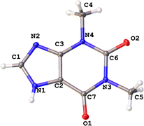
The contribution of the zwitterionic structure II to the molecular geometry leads to the slightly elongation of the C2–C3 bond and shortening of the C2–C7 bond in the THP molecule found in all studied structures (Fig. 3 and Table 3). The difference between carbonyl groups is identified by their bond critical points (BCP) characteristics derived from X-ray diffraction data (Table 4). Elongation of the C7–O1 bond results in lower ellipticity at its BCP in the THP molecule in all polymorphic forms. It should be noted, that the carbonyl bond C7–O1 can be easier enolized than that of C6–O2. This is probably a consequence of the stronger conjugation between the endocyclic C![[double bond, length as m-dash]](https://www.rsc.org/images/entities/char_e001.gif) C and exocyclic C
C and exocyclic C![[double bond, length as m-dash]](https://www.rsc.org/images/entities/char_e001.gif) O double bonds as compared to the conjugation between the electron lone pair of a nitrogen atom and the carbonyl bond.64 Moreover, it is well known that the polar environment may lead to significant re-distribution of electron density and polarization of a molecule.65
O double bonds as compared to the conjugation between the electron lone pair of a nitrogen atom and the carbonyl bond.64 Moreover, it is well known that the polar environment may lead to significant re-distribution of electron density and polarization of a molecule.65
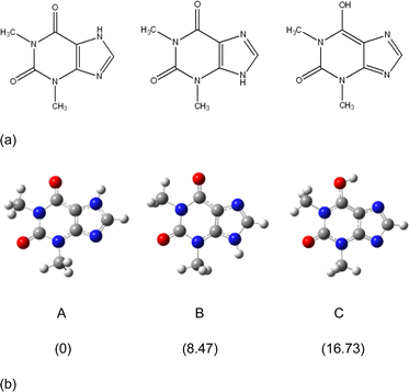 | ||
| Fig. 4 (a) Three possible tautomers of THP. (b) Optimized structures of the three THP tautomers and their relative energies (kcal mol−1) calculated by the m06-2x/cc-PVTZ method. | ||
| Bond | ρ(r), e per a.u.3 | −∇2ρ(r), e per a.u.5 | ε | ν(r), a.u. | |
|---|---|---|---|---|---|
| 1 | O2–C6 | 0.4293 | −0.1848 | 0.11 | −1.5180 |
| O1–C7 | 0.4051 | −0.3714 | 0.10 | −1.3557 | |
| C2–C3 | 0.3520 | −1.1081 | 0.29 | −0.5372 | |
| C2–C7 | 0.3065 | −0.9299 | 0.17 | −0.3989 | |
| 2 | O2–C6 | 0.4069 | −0.4923 | 0.12 | −1.3383 |
| O1–C7 | 0.4082 | −0.3296 | 0.10 | −1.3804 | |
| C2–C3 | 0.3412 | −1.0419 | 0.28 | −0.5076 | |
| C2–C7 | 0.3088 | −0.9430 | 0.17 | −0.4052 | |
| 3 | O2–C6 | 0.4152 | −0.3670 | 0.12 | −1.4098 |
| O1–C7 | 0.4086 | −0.3250 | 0.10 | −1.3831 | |
| C2–C3 | 0.3326 | −0.9899 | 0.28 | −0.4839 | |
| C2–C7 | 0.3011 | −0.8985 | 0.17 | −0.3864 | |
| 4 | O2–C6 | 0.3998 | −0.5567 | 0.12 | −1.2887 |
| O1–C7 | 0.3863 | −0.6078 | 0.10 | −1.2057 | |
| C2–C3 | 0.3237 | −0.9399 | 0.27 | −0.4598 | |
| C2–C7 | 0.3089 | −0.9406 | 0.17 | −0.4064 | |
| 5A | O2–C6 | 0.4149 | −0.3720 | 0.12 | −1.4067 |
| O1–C7 | 0.3942 | −0.3900 | 0.08 | −1.2956 | |
| C2–C3 | 0.3365 | −1.0183 | 0.27 | −0.4939 | |
| C2–C7 | 0.3090 | −0.9347 | 0.18 | −0.4084 | |
| 5B | O2–C6 | 0.4156 | −0.3483 | 0.12 | −1.4153 |
| O1–C7 | 0.3949 | −0.3944 | 0.08 | −1.2984 | |
| C2–C3 | 0.3365 | −1.0182 | 0.27 | −0.4944 | |
| C2–C7 | 0.3083 | −0.9296 | 0.19 | −0.4065 |
A study of 1-imino-1H-isoindol-3-amine and its derivatives reveals unusual distribution of bond lengths within the NH2–C![[double bond, length as m-dash]](https://www.rsc.org/images/entities/char_e001.gif) N amidine fragment. It was demonstrated that strong polarization of the amidine fragment is caused by the polarizing influence of the molecular surrounding in the crystal phase.65 Since the influence of a polarizing environment is often associated with the formation of specific intermolecular interactions in a crystal, ranging from strong hydrogen bonds to weak interactions, we analysed the intermolecular interactions in the crystals under study.
N amidine fragment. It was demonstrated that strong polarization of the amidine fragment is caused by the polarizing influence of the molecular surrounding in the crystal phase.65 Since the influence of a polarizing environment is often associated with the formation of specific intermolecular interactions in a crystal, ranging from strong hydrogen bonds to weak interactions, we analysed the intermolecular interactions in the crystals under study.
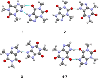
According to the Etter's rules24,25 and Desiraju's synthon concept26,27 for the classification of hydrogen bonds, all strong proton donors and acceptors should participate in the formation of hydrogen bonds in a crystal. The THP molecule contains several strong proton acceptors (the nitrogen atom of the purine moiety and the oxygen atoms of the carbonyl groups) and only one strong proton donor (the NH group). Accordingly, the most likely motive is a centrosymmetric dimer formed by N1–H⋯O1 hydrogen bonds. However, this prediction is only realized in the structures 4–7. In all others crystals, non-centrosymmetric dimers formed by N1–H⋯N2 or N1–H⋯O2 hydrogen bonds are observed (Fig. 5, Table 5).
| Structure | Interaction | Symmetry operation | H⋯A, Å | D–H⋯A, deg. |
|---|---|---|---|---|
| 1 | N1–H1N⋯N2 | 0.5 + x, −y, −0.5 + z | 1.999 | 175 |
| C1–H1⋯O1 | 0.5 + x, −y, −0.5 + z | 2.422 | 138 | |
| C4–H4B⋯O1 | x, y, −1 + z | 2.584 | 151 | |
| Stacking (C3⋯C2) | 1 + x, y, z | 3.42 | ||
| 2 | N1–H1N⋯O2 | 0.5 + x, 1.5 − y, −1 + z | 1.883 | 154 |
| C1–H1⋯N2 | 2 − x, 1 − y, 0.5 + z | 2.419 | 152 | |
| C4–H4B⋯O1 | 0.5 + x, 1.5 − y, z | 2.419 | 173 | |
| Stacking (C7⋯N4) | 1 − x, −y, 1 − z | 3.45 | ||
| 3 | N1–H1N⋯N2 | 0.5 − x, −0.5 + y, 0.5 + z | 1.906 | 178 |
| C1–H1⋯O1 | 0.5 − x, −0.5 + y, −0.5 + z | 2.363 | 159 | |
| C1–H1⋯C4(π) | 0.5 − x, −0.5 + y, −0.5 + z | 2.796 | 153 | |
| C5–H5B⋯O2 | 1 − x, 2 − y, −0.5 + z | 2.664 | 134 | |
| C5–H5C⋯O2 | 1 − x, 2 − y, −0.5 + z | 2.659 | 110 | |
| C5–H5A⋯O1 | x, −1 + y, z | 2.711 | 135 | |
| H5A⋯H5B | x, −1 + y, z | 2.217 | ||
| Stacking (C3⋯N4) | x, −1 + y, z | 3.41 | ||
| 4 | N1–H1N⋯O1 | −1 − x, −1 − y, −z | 1.650 | 173 |
| C1–H1⋯O2 | −1 + x, −0.5 − y, −0.5 + z | 2.108 | 165 | |
| C4–H4A⋯N2(π) | −x, −y, −z | 2.714 | 158 | |
| C4–H4B⋯N2(π) | x, −0.5 − y, −0.5 + z | 2.743 | 141 | |
| C5–H5A⋯N2(π) | x, −0.5 − y, −0.5 + z | 2.639 | 167 | |
| H5A⋯H5B | 1 − x, 0.5 + y, 0.5 − z | 2.301 | ||
| 5 | N1A–H1NA⋯O1B | x, y, z | 1.793 | 167 |
| N1B–H1NB⋯O1A | 1.794 | 163 | ||
| C1B–H1B⋯O2A | −x, −0.5 + y, 0.5 − z | 2.381 | 141 | |
| C1A–H1A⋯N2B | x, 0.5 − y, 0.5 + z | 2.287 | 165 | |
| C4B–H4BB⋯O2B | 2 − x, −y, 1 − z | 2.582 | 160 | |
| C4A–H4AC⋯O2B | −1 + x, 1 + y, z | 2.660 | 116 | |
| C4B–H4BC⋯C7B(π) | 1 − x, −y, 1 − z | 2.883 | 145 | |
| C5B–H5BB⋯O2A(π?) | 2 − x, −y, 1 − z | 2.671 | 130 | |
| Stacking (N1A⋯C6B) | 1 − x, −y, 1 − z | 3.39 | ||
| 6 | N1A–H1NA⋯O1A | x, y, z | 1.882 | 160 |
| N1B–H1NB⋯O1B | ||||
| C1A–H1A⋯O2A | −1 − x, −0.5 + y, 1 − z | 2.264 | 176 | |
| C1B–H1B⋯O2B | 2 − x, 0.5 + y, 2 − z | 2.265 | 176 | |
| C5A–H5AA⋯C4A(π) | 1 + x, y, z | 2.864 | 119 | |
| C5B–H5AB⋯C4B(π) | −1 + x, y, z | 2.873 | 118 | |
| O1W–H1WA⋯O2W | x, y, z | 1.839 | 172 | |
| C4A–H4AA⋯O1W | x, y, z | 2.623 | 152 | |
| O2W–H2WA⋯N2B | x, y, z | 2.057 | 164 | |
| O1W–H1WA⋯N2A | 2.040 | 165 | ||
| Stacking (C3A⋯C7A) | 1 + x, y, z | 3.347 | ||
| Stacking (C3B⋯C7B) | −1 + x, y, z | 3.353 | ||
| 7 | N1–H1N⋯O1 | 1 − x, 1 − y, 1 − z | 1.923 | 170 |
| C1–H1⋯O2 | 1 − x, 1 − y, 1 − z | 2.400 | 156 | |
| C4–H4A⋯O2 | 1 − x, 1 − y, 1 − z | 2.675 | 142 | |
| C4–H4B⋯C1(π) | x, y, z | 2.819 | 141 | |
| N2⋯I1 | x, y, z | 2.889 | 177 | |
| O1⋯C7 | x, y, z | 3.214 |
Thus, different packing patterns are formed by the N–H⋯O and N–H⋯N hydrogen bonds. We can recognize two types of packing motifs: zig-zag chains dominate in the structures 1, 3, 4 and 6 and infinite linear chains are observed in the structures 2, 5 and 7 (Fig. 6, Table 5).
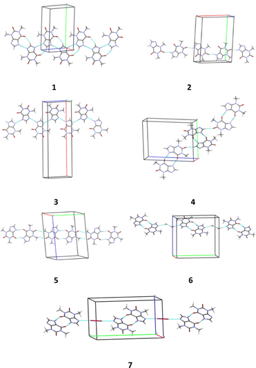 | ||
| Fig. 6 Packing patterns formed by the strongest intermolecular interactions (hydrogen bonds and halogen bonds) in structures 1–7. | ||
In addition to strong hydrogen bonds, weak interactions (C–H⋯O/N and C–H⋯π H-bonds) connected the main dimers inside the chains were also revealed in the crystals under study (Table 4). Additionally, the presence of the conjugated π-system in the THP molecule results in the existence of stacking interactions. In the studied polymorphic structures of THP two types of stacking are observed: head-to-head and head-to-tail orientation of stacked molecules (Table 5).
The analysis of intermolecular interactions in the crystals 6 and 7 has revealed additional H-bonds with the solute water molecule in the case of monohydrate of THP or the I⋯N halogen bonds in the case of co-crystal with iodine. It should be noted that we did not observe stacking interactions in the crystal 7 due to the small degree of overlap between neighbouring THP molecules. However, an interaction between carbonyl groups which can be characterized as a π⋯π interaction was found in this crystal structure.
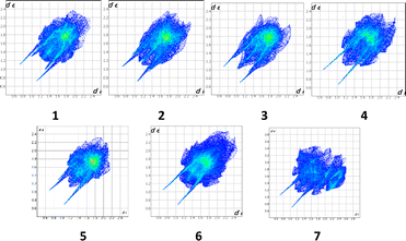
A convenient method to compare intermolecular interactions is the Hirshfeld surface analysis using the Crystal Explorer program.66 To study the crystal structures of THP and its co-crystals it is useful to compare their 2D fingerprint plots (Fig. 7).
The 2D fingerprint plots allows one to analyse the intermolecular interactions within a crystal in general (Fig. 5) and obtain the contribution (in %) of the interactions of defined type in particular (Fig. 6). The long sharp spikes indicate the presence of strong enough hydrogen bonds in the crystals 1–7 (Fig. 7). Comparing the 2D fingerprint plots we may conclude that the shortest hydrogen bond contacts and interactions are present in the structure 2 while the longest hydrogen bond contacts are observed in the structures 4, 5 and 6.
It was revealed that the contributions of the intermolecular interactions of defined types to the crystal structure formation (Fig. 8) are relatively similar in crystals 1–6. The histogram clearly shows that the contributions of the N/C–H⋯O and N/C–H⋯N hydrogen bonds are almost the same in these crystals. The relationship between intermolecular interactions is slightly different in the structure 7. In 7 the contribution of all intermolecular interactions decreases and stacking interactions almost completely disappear in this structure as compared to other structures under study (Fig. 8).
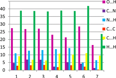 | ||
| Fig. 8 The relative contribution of intermolecular interactions of different types (in %) estimated by the 2D fingerprint plots analysis. | ||
Unfortunately, the analysis of the geometries of intermolecular interactions does not allow one to come to definite conclusions about structural motifs of crystal packing and role of different types interactions in crystal structure formation. Crystal packing analysis based on the study of pairwise interaction energies obtained from the quantum-chemical calculations takes into account all existing types of interactions (specific and non-specific) and allows us to go from a qualitative description of a crystal structure to detailed quantitative analysis of it.34 It should be noted that this approach may be applied not only to a molecule as a simple building unit (BU) of a crystal packing but also to a dimer, trimer or tetramer of molecules as a complex building unit.
The first coordination sphere of the building units (molecule or dimer) located in the asymmetric part of the unit cell in all the studied crystals contains 12–36 neighbouring ones. The full list of symmetry operations and interaction energies for the corresponding dimers are given in ESI (Tables S1–S7†). The selected data for the dimers with interaction energies stronger than 5% (3% in the case of co-crystals) of the total interaction energy of the basic molecule with all molecules belonging to its first coordination sphere are shown in Tables 6–12.
| Dimer | Symmetry operation | Eint, kcal mol−1 | Contribution to the total Eint,% | Interaction type |
|---|---|---|---|---|
| 1-m1 | −1/2 + x, −y, 1/2 + z | −12.1 | 20.3 | N1–H⋯N2 1.84 Å, 174° |
| 1-m2 | 1/2 + x, −y, −1/2 + z | −12.1 | 20.3 | N1–H⋯N2 1.84 Å, 174° |
| 1-m3 | −1 + x, y, z | −8.1 | 13.5 | Stacking, C2⋯C5 3.42 Å |
| 1-m4 | 1 + x, y, z | −8.1 | 13.5 | Stacking, C2⋯C5 3.42 Å |
| 1-m5 | −1/2 + x, −y, −1/2 + z | −4.2 | 7.0 | C1–H⋯π 3.09 Å, 133° |
| 1-m6 | 1/2 + x, −y, 1/2 + z | −4.2 | 7.0 | C1–H⋯π 3.09 Å, 133° |
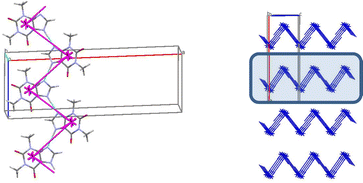
In the crystal 1 a basic molecular building unit (MBU0) forms two the same interactions (N1–H⋯N2 hydrogen bonds) in opposite directions (Table 6). As a result, the column may be recognized as a primary basic structural motif (BSM1) (Fig. 9). The interaction energy of MBU0 with all neighbouring MBUi within this column is −24.2 kcal mol−1. The anisotropy of interactions of the BSM1 with neighbouring ones allows us to separate out the layer of strongly bound columns as a secondary BSM2 of structure 1 (Fig. 9). The analysis of intermolecular interactions has revealed that the molecules belonging to neighbouring columns are bound by C–H⋯π hydrogen bonds and stacking interactions within the layer. The interaction energy of the basic molecule within the layer is seven times higher as the interaction energy between neighbouring layers (Table 13). The interactions between BSM2 are provided by weaker C–H⋯O hydrogen bonds. Thus, structure 1 has two levels of organization, and can be recognized as a typical columnar-layered structure.
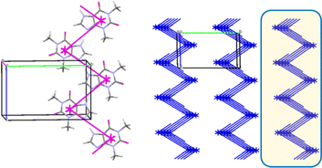
The basic molecule of structure 2 is surrounded by 14 neighbouring ones and interacts with them with the total energy of −59.1 kcal mol−1. The analysis of pairwise interaction energies revealed that the basic molecule forms two of the strongest interactions (the N1–H⋯O2 hydrogen bonds) with the molecules located in the opposite directions (Table 7). These interactions have the same energy (−10.8 kcal mol−1) and form a column, which may be recognized as the BSM1 in the crystal of 2 (Fig. 10). In contrast to the column in structure 1, the ones that are strongly bound with the basic molecules form a straight line in 2 (Fig. 8). The interaction energy of a basic molecule within the column is −21.6 kcal mol−1.
| Dimer | Symmetry operation | Eint, kcal mol−1 | Contribution to the total Eint,% | Interaction type |
|---|---|---|---|---|
| 2-m1 | −1/2 + x, 3/2 − y, 1 + z | −10.8 | 18.2 | N1–H⋯O2 1.79 Å, 153° |
| 2-m2 | 1/2 + x, 3/2 − y, −1 + z | −10.8 | 18.2 | N1–H⋯O2 1.79 Å, 153° |
| 2-m3 | x, y, −1 + z | −8.0 | 13.5 | Stacking, C7⋯N4 3.40 Å |
| 2-m4 | x, y, 1 + z | −8.0 | 13.5 | Stacking, C7⋯N4 3.40 Å |
| 2-m5 | −1/2 + x, 3/2 − y, z | −4.0 | 6.8 | C4–H⋯O1 2.29 Å, 173° |
| 2-m6 | 1/2 + x, 3/2 − y, z | −4.0 | 6.8 | C4–H⋯O1 2.29 Å, 173° |
| 2-m7 | 2 − x, 1 − y, −1/2 + z | −3.3 | 5.6 | C1–H⋯N2 2.28 Å, 151° |
| 2-m8 | 2 − x, 1 − y, 1/2 + z | −3.3 | 5.6 | C1–H⋯N2 2.28 Å, 151° |
The anisotropy of interactions of the BSM1 with neighbouring ones allows to separate out the layer of columns as the secondary BSM (BSM2) of structure 2 (Fig. 10). The analysis of intermolecular interactions has revealed that the molecules of neighbouring columns within the layer are bound by stacking interactions and C–H⋯O hydrogen bonds. The interaction energy of the basic molecule within the layer (−45.6 kcal mol−1) is three times as high as the interaction energy between neighbouring layers (−13.6 kcal mol−1). The interactions between BSM2 are provided by weak C–H⋯N hydrogen bonds and non-specific interactions. Thus structure 2 obviously also has two levels of organization.
Similar to structure 2, the first coordination sphere of the basic molecule contains 14 neighbouring molecules in structure 3. However, the total interaction energy of the basic molecule with all neighbouring ones is a little bit bigger (−60.2 kcal mol−1). The analysis of pairwise interaction energies revealed that the basic molecule also forms two identical interactions with the highest energy in 3 (Table 8). The bond angle formed by geometric centers of the basic molecule and neighbouring molecules strongly bound with it is almost the same as in the structure 1 (78° in 1 and 79° in 3). As a result, the corrugated columns (Fig. 11) similar to the structure 1 can be recognized as the primary basic structural motif (BSM1) in the crystal structure 3. The molecules within the column are bound by the N1–H⋯N2 hydrogen bonds. Despite the more efficient geometrical characteristics of these hydrogen bonds, the total interaction energy of a basic molecule with its neighbours within the column is smaller as those in the structure 1 (−20.6 kcal mol−1).
| Dimer | Symmetry operation | Eint, kcal mol−1 | Contribution to the total Eint,% | Interaction type |
|---|---|---|---|---|
| 3-m1 | 1/2 − x, −1/2 + y, 1/2 + z | −10.3 | 17.2 | N1–H⋯N2 1.77 Å, 178° |
| 3-m2 | 1/2 − x, 1/2 + y, −1/2 + z | −10.3 | 17.2 | N1–H⋯N2 1.77 Å, 178° |
| 3-m3 | x, −1 + y, z | −8.1 | 13.5 | Stacking, C1⋯N2 3.41 Å |
| 3-m4 | x, 1 + y, z | −8.1 | 13.5 | Stacking, C1⋯N2 3.41 Å |
| 3-m5 | 1/2 − x, −1/2 + y, −1/2 + z | −4.8 | 7.9 | C1–H⋯O1 2.23 Å, 158° |
| 3-m6 | 1/2 − x, 1/2 + y, 1/2 + z | −4.8 | 7.9 | C1–H⋯O1 2.23 Å, 158° |
The interactions of the BSM1 with neighbouring ones also are not equal that allows to separate out the layer of columns as the secondary BSM2 of structure 3 (Fig. 11). The molecules of neighbouring columns within the layer are bound by C–H⋯O hydrogen bonds and stacking interactions. The interaction energy of the basic molecule within the layer is −52.4 kcal mol−1, which is six times higher than the interaction energy between neighbouring layers (−7.8 kcal mol−1). The neighbouring layers are bound by weaker C–H⋯O hydrogen bonds and non-specific interactions. Therefore, structure 3 can also be recognized as a columnar-layered structure.
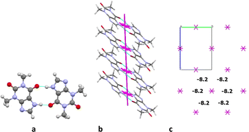
The first coordination sphere of a basic molecule contains 12 neighbouring ones in structure 4. The total interaction energy of the basic molecule with all the neighbouring molecules is −61.7 kcal mol−1. The analysis of pairwise interaction energies revealed that the basic molecule forms only one the strongest interaction (Table 9). The interaction energy (−20.3 kcal mol−1) within the centrosymmetric dimer bound by two the N1–H⋯O1 hydrogen bonds (Fig. 12a) is almost four times higher than the interaction within the other dimers. So, this dimer may be recognized as a complex dimeric building unit (DBU0) of structure 4.
| Dimer | Symmetry operation | Eint, kcal mol−1 | Contribution to the total Eint,% | Interaction type |
|---|---|---|---|---|
| Molecular building unit (MBU0) | ||||
| 4-m1 | −1 − x, −1 − y, −z | −20.3 | 32.3 | N1–H⋯O1 1.77 Å, 178° |
| 4-m2 | −1 + x, y, z | −8.1 | 12.9 | C–H⋯π 2.74 Å, 141° |
| 4-m3 | 1 + x, y, z | −8.1 | 12.9 | C–H⋯π 2.74 Å, 141° |
| 4-m4 | −x, −1 − y, −z | −5.9 | 9.4 | Non-specific |
| 4-m5 | −1 + x, −1/2 − y, −1/2 + z | −4.3 | 6.8 | C1–H⋯O2 2.11 Å, 165° |
| 4-m6 | 1 + x, −1/2 − y, 1/2 + z | −4.3 | 6.8 | C1–H⋯O2 2.11 Å, 165° |
| 4-m7 | −x, −y, −z | −3.4 | 5.4 | C–H⋯π 2.72 Å, 158° |
![[thin space (1/6-em)]](https://www.rsc.org/images/entities/char_2009.gif) |
||||
| Dimeric building unit (DBU0) | ||||
| 4-d1 | −1 + x, y, z | −21.7 | 25.1 | Stacking, C6⋯C7 3.41 Å |
| 4-d2 | 1 + x, y, z | −21.7 | 25.1 | Stacking, C6⋯C7 3.41 Å |
| 4-d3 | −1 + x, −3/2 − y, −1/2 + z | −4.5 | 5.3 | C1–H⋯O2 2.11 Å, 165° |
| 4-d4 | −1 + x, −1/2 − y, −1/2 + z | −4.5 | 5.3 | C1–H⋯O2 2.11 Å, 165° |
| 4-d5 | 1 + x, −3/2 − y, 1/2 + z | −4.5 | 5.3 | C1–H⋯O2 2.11 Å, 165° |
| 4-d6 | 1 + x, −1/2 − y, 1/2 + z | −4.5 | 5.3 | C1–H⋯O2 2.11 Å, 165° |
| 4-d7 | −1 + x, −1 + y, z | −3.6 | 4.2 | C4–H⋯N2 2.72 Å, 158° |
| 4-d8 | 1 + x, 1 + y, z | −3.6 | 4.2 | C4–H⋯N2 2.72 Å, 158° |
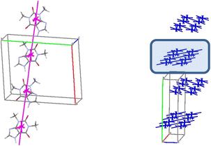
A basic dimeric building unit is surrounded by 18 neighbouring dimers and forms the strongest interactions with two of them (Table 9). As a result, the column of dimers may be considered as the primary basic structural motif (BSM1) in the crystal 4 (Fig. 12b). The total interaction energy of DBU0 with the neighbouring dimers within the column is −43.4 kcal mol−1. Dimers within the column are bound by the stacking interactions. The interaction energy between the neighbouring columns is almost equal and five times as smaller than the interaction energy within the column (−8.2 kcal mol−1) being provided by C–H⋯O, C–H⋯N hydrogen bonds and non-specific interactions. Therefore, the crystal structure 4 has only one level of organization and may be classified as columnar (Fig. 12c).
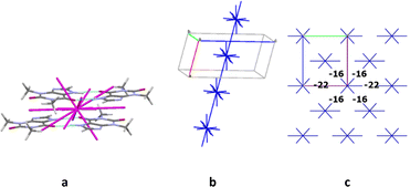
The crystals of structure 5 contain two molecules A and B in the asymmetric part of the unit cell. These molecules form a centrosymmetric dimer due to the N–H⋯O intermolecular hydrogen bonds similar to the structure 4. This dimer was recognized as a dimeric building unit of the structure 5. The first coordination sphere of a basic dimer contains 18 neighbouring ones in the structure 5. The total interaction energy of the DBU0 with the neighbouring ones is −88.8 kcal mol−1. The analysis of pairwise interaction energies revealed also that the basic building unit forms only one the strongest interaction (Table 10). The interaction energy (−21.0 kcal mol−1) within the tetramer bound by the stacking interactions “head-to-head” type (Fig. 13a) is much higher than the interaction within the other tetramers. Therefore, this tetramer may be recognized as a complex tetrameric building unit (TBU0) of structure 5.
| Dimer | Symmetry operation | Eint, kcal mol−1 | Contribution to the total Eint,% | Interaction type |
|---|---|---|---|---|
| Dimeric building unit (DBU0) | ||||
| 5-d1 | 1 − x, 1 − y, 1 − z | −21.0 | 23.6 | Stacking 3.29 Å |
| 5-d2 | −x, 1 − y, 1 − z | −14.2 | 16.0 | Stacking 3.39 Å |
| 5-d3 | 1 − x, −y, 1 − z | −10.5 | 11.8 | Stacking 3.47 Å |
| 5-d4 | x, 1/2 − y, −1/2 + z | −4.5 | 5.1 | C–H⋯N 2.20 Å, 164° |
| 5-d5 | x, 1/2 − y, 1/2 + z | −4.5 | 5.1 | C–H⋯N 2.20 Å, 164° |
![[thin space (1/6-em)]](https://www.rsc.org/images/entities/char_2009.gif) |
||||
| Tetrameric building unit (TBU0) | ||||
| 5-t1 | −1 + x, y, z | −16.7 | 11.8 | Stacking 3.39 Å |
| 5-t2 | 1 + x, y, z | −16.7 | 11.8 | Stacking 3.39 Å |
| 5-t3 | x, −1 + y, z | −11.2 | 7.9 | Stacking 3.47 Å |
| 5-t4 | x, 1 + y, z | −11.2 | 7.9 | Stacking 3.47 Å |
| 5-t5 | −1 + x, 1 + y, z | −10.8 | 7.6 | C–H⋯O 2.61 Å, 114° |
| 5-t6 | 1 + x, −1 + y, z | −10.8 | 7.6 | C–H⋯O 2.61 Å, 114° |
| 5-t7 | 1 − x, −1/2 + y, 1/2 − z | −9.9 | 7.0 | C–H⋯N 2.20 Å, 164° |
| 5-t8 | 1 − x, −1/2 + y, 3/2 − z | −9.9 | 7.0 | C–H⋯N 2.20 Å, 164° |
| 5-t9 | 1 − x, 1/2 + y, 1/2 − z | −9.9 | 7.0 | C–H⋯N 2.20 Å, 164° |
| 5-t10 | 1 − x, 1/2 + y, 3/2 − z | −9.9 | 7.0 | C–H⋯N 2.20 Å, 164° |
The TBU0 is surrounded by 14 neighbouring tetramers and forms the strongest interactions with two of them in different directions (Table 10). As a result, a stacked column of tetramers may be considered as a primary basic structural motif (BSM1) in the crystal 5 (Fig. 13b). The total interaction energy of TBU0 with the neighbouring tetramers within the column is −33.4 kcal mol−1. The interaction energies between the neighbouring columns are almost equal in four directions and slightly higher in other two directions. By the way, all these energies are smaller than the interaction energies within the column (−16.0 ÷ −22.0 kcal mol−1) and are provided by weaker C–H⋯O, C–H⋯N hydrogen bonds and non-specific interactions. Thus, similar to crystal structure 4, the structure 5 has only one level of organization and may be classified as columnar (Fig. 13c). Additionally, it should be noted that in this case we can characterize this crystal packing as denser than in crystal 4, because the energies between adjacent columns are almost two times smaller than the interaction energies within the column (Fig. 13c).
The basic molecule is surrounded by 36 neighbouring molecules in the structure 6. This is the biggest number of neighbours from all the structures under study. It may be caused by the presence of the water molecule in the crystal (Fig. 14). Similar to the structures 4 and 5, the centrosymmetric dimer formed by N1–H⋯O1 hydrogen bond can be recognized as a complex dimeric building unit (DBU0) of structure 6 (Fig. 14). The DBU0 is strongly bound with two neighbouring dimers due to stacking interactions with each of them (Table 11). Hence, the stacked column may be recognized as a primary basic structural motif (BSM1) in structure 6 (Fig. 14). The interaction energy of the basic dimer within this column is −38.0 kcal mol−1. Each of the dimers within the column connects with four THP dimers and four water molecules (Fig. 14). The dimers belonging to the neighbouring columns are bound mainly by O–H⋯N and C–H⋯O hydrogen bonds.
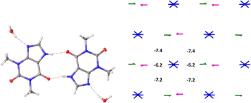 | ||
| Fig. 14 Dimer as a building unit (left) and packing of columns in term of energy-vector diagrams, projection in a crystallographic direction (right) in the structure 6. | ||
| Dimer | Symmetry operation | Eint, kcal mol−1 | Contribution to the total Eint,% | Interaction type |
|---|---|---|---|---|
| 6-d1 | −1 + x, y, z | −19.0 | 15.4 | Stacking 3.35 Å |
| 6-d2 | 1 + x, y, z | −19.0 | 15.4 | Stacking 3.35 Å |
| 6-d3 | x, y, z | −6.2 | 5.0 | O–H⋯N 1.91 Å, 164° |
| 6-d4 | x, y, z | −6.2 | 5.0 | O–H⋯N 1.94 Å, 164° |
| 6-d5 | 1 − x, −1/2 + y, 2 − z | −4.2 | 3.4 | C–H⋯O 2.64 Å, 126° |
| 6-d6 | 1 − x, 1/2 + y, 2 − z | −4.2 | 3.4 | C–H⋯O 2.64 Å, 126° |
| 6-d7 | −x, −1/2 + y, 1 − z | −3.9 | 3.2 | C–H⋯O 2.64 Å, 126° |
| 6-d8 | −x, 1/2 + y, 1 − z | −3.9 | 3.2 | C–H⋯O 2.64 Å, 126° |
The interaction energies between THP molecules belonging to the neighbouring columns do not allow us to separate out any secondary structural motif (Fig. 14). Therefore, crystal structure 6 has only one level of organization and may be classified as columnar. It should be noted that the interactions energies within the column and between them in the structure 6 are really close to those in the crystal structure 4.
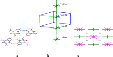
The first coordination sphere contains 26 neighbouring molecules in the structure 7. The centrosymmetric N1–H⋯O1 hydrogen bonded dimer may also be recognized as the complex DBU0 of structure 7. However, this dimer has the smallest interaction energy compared to those calculated for 4, 5 or 6. This is most likely due to presence of halogen atoms in this crystal structure (Table 12). As a result, we can observe new types of interactions in the structure 7, which can play a key role in the formation of supramolecular architecture of this crystal (Table 12). Thus, the column formed by two the strongest π⋯π interactions can be recognized as BSM1 (Fig. 15). The interaction energy of DBU0 with its neighbours within the column is −26.8 kcal mol−1. This is also the smallest energy with comparison of structures 4, 5 and 6 (Table 13). Similar to monohydrate structure each of the dimers belonging to the column connects with four THP dimers and four iodine molecules. However, the interactions between them are stronger (Fig. 15c). The neighbouring columns are bound by unexpected strong I⋯N interactions (Table 12). According to the literature halogen bonds are really rare play crucial role in supramolecular architecture of crystals from energetically viewpoint. However, if crystals contain only weak C–H⋯X hydrogen bonds then halogen bonds could connect basic structural motifs as the primary/secondary interactions.67,68 Furthermore, in the crystal of 7 much weaker C–H⋯N hydrogen bonds and I⋯π interactions bound BSMs.
| Dimer | Symmetry operation | Eint, kcal mol−1 | Contribution to the total Eint,% | Interaction type |
|---|---|---|---|---|
| 7-d1 | −1 − x, 1 − y, 1 − z | −13.4 | 9.9 | π⋯π 3.21 Å |
| 7-d2 | 1 − x, 1 − y, 1 − z | −13.4 | 9.9 | π⋯π 3.21 Å |
| 7-d3 | x, y, z | −9.9 | 7.3 | I⋯N 2.89 Å, 177° |
| 7-d4 | x, 1 + y, z | −9.9 | 7.3 | I⋯N 2.89 Å, 177° |
| 7-d5 | −x, −1/2 + y, 1/2 − z | −5.8 | 4.2 | C–H⋯N 2.72 Å, 166° |
| 7-d6 | −x, −1/2 + y, 3/2 − z | −5.8 | 4.3 | C–H⋯N 2.72 Å, 166° |
| 7-d7 | −x, 1/2 + y, 3/2 − z | −5.8 | 4.3 | C–H⋯N 2.72 Å, 166° |
| 7-d8 | −x, 1/2 + y, 1/2 − z | −5.8 | 4.3 | C–H⋯N 2.72 Å, 166° |
| 7-d9 | −x, 1/2 + y, 1/2 − z | −5.1 | 3.8 | I⋯π 2.89 Å, 177° |
| 7-d10 | −x, 1/2 + y, 3/2 − z | −5.1 | 3.8 | I⋯π 2.89 Å, 177° |
| Structure | Number of neighbors | Total Eint, kcal mol−1 | The dimer with the highest interaction energy | Building unit (BU) | Basic structural motif (BSM1/BSM2) | Eint (BSM1/BSM2), kcal mol−1 | Eint (BSM2/BSM2), kcal mol−1 | |
|---|---|---|---|---|---|---|---|---|
| Hydrogen bond | Eint, kcal mol−1 | |||||||
| 1 | 12 | −51.6 | N1–H⋯N2 | −12.1 | Molecule | Column/layer | −24.2/−52.6 | −7.2 |
| 2 | 14 | −59.1 | N1–H⋯O2 | −10.8 | Molecule | Column/layer | −21.6/−45.6 | −13.6 |
| 3 | 14 | −60.2 | N1–H⋯N2 | −10.3 | Molecule | Column/layer | −20.6/−52.4 | −7.8 |
| 4 | 12 | −61.7 | N1–H⋯O1 | −20.3 | Dimer | Column | −43.4 | −8.2 |
| 5 | 18 | −88.8 | N1–H⋯O1 | −21.0 | Tetramer | Column | −33.4 | −16 ÷ −22 |
| 6 | 36 | −120.8 | N1–H⋯O1 | −19.6 | Dimer | Column | −38.0 | −6.2 ÷ −7.4 |
| 7 | 26 | −97.8 | N1–H⋯O1 | −13.0 | Dimer | Column | −26.8 | −5.1 ÷ −9.9 |
It should be concluded that the structure 7 is also columnar, similar to structures 4, 5 and 6, but this crystal has more anisotropic structure in terms of the pairwise interaction energies (Fig. 15).
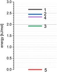
According to our previous studies69,70 such interactions of a basic molecule with its environment indicate that the polymorphic structure 5 is the most stable in comparison with other studied polymorphic structures (Table 13, Fig. 16).
Calculations of the lattice energies using the periodic approximation for all the polymorphic forms 1–5 of THP reveals that the structure 5 has the lowest lattice energy (Fig. 16). These results indicate that the structure 5 is the most stable form while the structures 1, 2, 3 and 4 can be considered as metastable.
Conclusion
All to date known polymorphic modifications of theophylline (THP), its monohydrate and a co-crystal with iodine were comprehensively studied. The reported structure of the monohydrate of THP exhibits some crystallographic pseudosymmetry issues, which were resolved before the structure (space group P21) was used for the analysis. The calculations of pairwise interaction energies between molecules have shown that three polymorphic forms (1, 2 and 3), where the building unit is a single molecule (MBU0), have a columnar-layered crystal structure. Strong N–H⋯N/O hydrogen bonds and stacking interactions play the main roles in the supramolecular architecture in these crystals. In the two others polymorphic modifications (4 and 5 structures), as well as in monohydrate and co-crystal (6 and 7 structures), the centrosymmetric dimer of THP molecules appears to be the building unit (DBU) of the corresponding crystal structures. The calculations of pairwise interaction energies between DBUs have revealed that these crystals have only one level of organization and can be characterized as columnar. The stacking interactions of the dimers contribute to the formation of these crystal structures. A comparison of interaction energies of tetrameric building unit TBU0 with its neighbouring molecules within the column and with ones belonging to adjacent columns indicates that the most stable crystal 5 has the densest packing from energetic point of view similar to the co-crystal with iodine 7.The presence of iodine molecules in the co-crystal causes disturbs the stacking interaction of the THP molecules and increases the role of the halogen interactions in crystal structure formation. The halogen interactions bind primary BSM1 in the structure 7. The calculations of the lattice energies using the periodic approximation show that 5 is the most stable structure, while 3, which is the polymorph used in the pharmaceutical industry, as well as structures 1, 2 and 4 are metastable.
Data availability
The data for all crystal structures the data were deposited with the CCDC (Cambridge crystallographic data center). The main results and outputs of the theoretical calculations are stored in the ESI.†Author contributions
The manuscript was written through contributions of all authors. All authors have given approval to the final version of the manuscript.Conflicts of interest
There are no conflicts to declare.Acknowledgements
This project has received funding through the MSCA4Ukraine project, which is funded by the European Union. This study was financially supported by the Ministry of Innovation, Science and Research of North-Rhine Westphalia and the German Research Foundation (DFG) (Xcalibur diffractometer; INST 208/533-1, project no. 162659349).References
- C. B. Aakeröy, A. M. Beatty and B. A. Helfrich, Angew. Chem., Int. Ed., 2001, 40, 3240 CrossRef.
- R. Hilfiker, Polymorphism in the Pharmaceutical Industry, Wiley-VCH, Weinheim, 2006 Search PubMed.
- R. J. Davey, Cryst. Growth Des., 2002, 2, 675 CrossRef CAS.
- H. G. Brittain, Polymorphism of Pharmaceutical Solids, Drugs and the pharmaceutical sciences, Informa Healthcare, New York, 2nd edn, 2009, vol. 192 Search PubMed.
- A. Kossel, Biol. Chem., 1889, 13, 298 CrossRef.
- A. Kossel, Ber. Dtsch. Chem. Ges., 1888, 21, 2164 CrossRef.
- K. Fucke, G. J. McIntyre, C. Wilkinson, M. Henry, J. A. K. Howard and J. W. Steed, Cryst. Growth Des., 2012, 12, 1395 CrossRef CAS.
- K. Matsuo and M. Matsuoka, Cryst. Growth Des., 2007, 7, 411 CrossRef CAS.
- R. Tanaka, Y. Hattori, M. Otsuka and K. Ashizawa, Drug Dev. Ind. Pharm., 2020, 46, 179 CrossRef CAS PubMed.
- F. Benaouda, S. A. Jones, J. Chana, B. M. Dal Corno, D. J. Barlow, R. C. Hider, C. P. Page and B. Forbes, Mol. Pharmaceutics, 2018, 15, 861 CrossRef CAS PubMed.
- Z. M. Sofian, F. Benaouda, J. T.-W. Wang, Y. Lu, D. J. Barlow, P. G. Royall, D. B. Farag, K. M. Rahman, K. T. Al-Jamal, B. Forbes and S. A. Jones, Adv. Ther., 2020, 3, 2000153 CrossRef CAS PubMed.
- C. G. Persson, J. Allergy Clin. Immunol., 1986, 78, 780 CrossRef CAS PubMed.
- C. R. Groom, I. J. Bruno, M. P. Lightfoot and S. C. Ward, Acta Crystallogr., Sect. B: Struct. Sci., Cryst. Eng. Mater., 2016, 72, 171 CrossRef CAS PubMed.
- C. Sun, D. Zhou, D. J. W. Grant and V. G. Young, Acta Crystallogr., Sect. E: Struct. Rep. Online, 2002, 58, o368 CrossRef CAS.
- D. J. Sutor, Acta Crystallogr., 1958, 11, 83 CrossRef CAS.
- S. Majodina, L. Ndima, O. O. Abosede, E. C. Hosten, C. M. A. Lorentino, H. F. Frota, L. S. Sangenito, M. H. Branquinha, A. L. S. Santos and A. S. Ogunlaja, CrystEngComm, 2021, 23, 335–352 RSC.
- E. M. Paiva, Q. Li, A. J. Zaczek, C. F. Pereira, J. J. R. Rohwedder and J. A. Zeitler, Mol. Pharmaceutics, 2021, 18, 3578 CrossRef CAS PubMed.
- M. TalwelkarShimpi, S. Öberg, L. Giri and V. R. Pedireddi, RSC Adv., 2016, 6, 43060 RSC.
- D.-K. Bučar, R. F. Henry, G. G. Z. Zhang and L. R. MacGillivray, Cryst. Growth Des., 2014, 14, 5318 CrossRef.
- A. Karagianni, J. Quodbach, O. Weingart, A. Tsiaxerli, V. Katsanou, V. Vasylyeva, C. Janiak and K. Kachrimanis, Solids, 2022, 3, 66–92 CrossRef CAS.
- T. Friscić, L. Fábián, J. C. Burley, W. Jones and W. D. S. Motherwell, Chem. Commun., 2006, 5009 RSC.
- G. J. Reiss, Z. Kristallogr.–New Cryst. Struct., 2019, 234, 737 CrossRef CAS.
- J. D. Dunitz and A. Gavezzotti, Chem. Soc. Rev., 2009, 38, 2622 RSC.
- M. C. Etter, J. Phys. Chem., 1991, 95, 4601 CrossRef CAS.
- M. C. Etter, Acc. Chem. Res., 1990, 23, 120 CrossRef CAS.
- G. R. Desiraju, Nature, 2001, 412, 397–400 CrossRef CAS PubMed.
- G. R. Desiraju, Angew. Chem., Int. Ed., 1995, 34, 2311 CrossRef CAS.
- A. I. Kitaĭgorodskiĭ, Molecular Crystals and Molecules, Physical chemistry, a series of monographs, Academic Press, New York, 1973, vol. 29 Search PubMed.
- I. S. Konovalova, S. V. Shishkina, B. V. Paponov and O. V. Shishkin, CrystEngComm, 2010, 12, 909 RSC.
- I. S. Konovalova, E. N. Muzyka, V. V. Urzhuntseva and S. V. Shishkina, Struct. Chem., 2021, 32, 235 CrossRef CAS.
- S. V. Shishkina, I. S. Konovalova, O. V. Shishkin and A. N. Boyko, CrystEngComm, 2017, 19, 6274 RSC.
- O. V. Shishkin, V. V. Dyakonenko and A. V. Maleev, CrystEngComm, 2012, 14, 1795 RSC.
- S. V. Shishkina, Struct. Chem., 2019, 30, 1565 CrossRef CAS.
- O. V. Shishkin, R. I. Zubatyuk, S. V. Shishkina, V. V. Dyakonenko and V. V. Medviediev, Phys. Chem. Chem. Phys., 2014, 16, 6773 RSC.
- L. S. Kikot', C. Y. Kulygina, A. Y. Lyapunov, S. V. Shishkina, R. I. Zubatyuk, T. Y. Bogaschenko and T. I. Kirichenko, Beilstein J. Org. Chem., 2017, 13, 2056 CrossRef PubMed.
- A. Lyapunov, T. Kirichenko, C. Kulygina, R. Zubatyuk, M. Fonari, A. Kyrychenko and A. Doroshenko, J. Inclusion Phenom. Macrocyclic Chem., 2015, 81, 499 CrossRef CAS.
- J. W. Steed and J. L. Atwood, Supramolecular Chemistry, Wiley, 2009 Search PubMed.
- C. F. Macrae, I. J. Bruno, J. A. Chisholm, P. R. Edgington, P. McCabe, E. Pidcock, L. Rodriguez-Monge, R. Taylor, J. van de Streek and P. A. Wood, J. Appl. Crystallogr., 2008, 41, 466 CrossRef CAS.
- P. Coppens, Acta Crystallogr., Sect. B: Struct. Sci., Cryst. Eng. Mater., 1972, 28, 1638 CrossRef CAS.
- F. Weigend and R. Ahlrichs, Phys. Chem. Chem. Phys., 2005, 7, 3297 RSC.
- A. Schäfer, H. Horn and R. Ahlrichs, Chem. Phys., 1992, 97, 2571–2577 Search PubMed.
- S. Grimme, S. Ehrlich and L. Goerigk, J. Comput. Chem., 2011, 32, 1456 CrossRef CAS PubMed.
- S. Grimme, J. Antony, S. Ehrlich and H. Krieg, Chem. Phys., 2010, 132, 154104 Search PubMed.
- S. Grimme, J. Comput. Chem., 2006, 27, 1787 CrossRef CAS PubMed.
- S. F. Boys and F. Bernardi, Mol. Phys., 1970, 19, 553 CrossRef CAS.
- L. Goerigk and S. Grimme, Phys. Chem. Chem. Phys., 2011, 13, 6670 RSC.
- F. Neese, Wiley Interdiscip. Rev.: Comput. Mol. Sci., 2012, 2, 73 CAS.
- T. A. Keith, TK Gristmill Software, Overland Park KS, USA, 2019, https://aim.tkgristmill.com Search PubMed.
- R. Dovesi, F. Pascale, B. Civalleri, K. Doll, N. M. Harrison, I. Bush, P. D'Arco, Y. Noël, M. Rérat, P. Carbonnière, M. Causà, S. Salustro, V. Lacivita, B. Kirtman, A. M. Ferrari, F. S. Gentile, J. Baima, M. Ferrero, R. Demichelis and M. De La Pierre, J. Chem. Phys., 2020, 152 Search PubMed.
- R. Dovesi, A. Erba, R. Orlando, C. M. Zicovich-Wilson, B. Civalleri, L. Maschio, M. Rérat, S. Casassa, J. Baima, S. Salustro and B. Kirtman, Wiley Interdiscip. Rev.: Comput. Mol. Sci., 2018, 8, e1360 Search PubMed.
- M. Bursch, J.-M. Mewes, A. Hansen and S. Grimme, Angew. Chem., Int. Ed., 2022, 61, e202205735 CrossRef CAS PubMed.
- A. D. Becke, Phys. Rev. A: At., Mol., Opt. Phys., 1988, 38, 3098 CrossRef CAS PubMed.
- C. Lee, W. Yang and R. G. Parr, Phys. Rev. B: Condens. Matter Mater. Phys., 1988, 37, 785–789 CrossRef CAS PubMed.
- S. Grimme, J. Antony, S. Ehrlich and H. A. Krieg, J. Chem. Phys., 2010, 132, 154104 CrossRef PubMed.
- S. Grimme, S. Ehrlich and L. Goerigk, J. Comput. Chem., 2011, 32, 1456 CrossRef CAS PubMed.
- S. Grimme, A. Hansen, J. G. Brandenburg and C. Bannwarth, Chem. Rev., 2016, 116, 5105 CrossRef CAS PubMed.
- H. Kruse and S. Grimme, J. Chem. Phys., 2012, 136, 154101 CrossRef PubMed.
- J. G. Brandenburg, M. Alessio, B. Civalleri, M. F. Peintinger, T. Bredow and S. Grimme, J. Phys. Chem. A, 2013, 117, 9282 CrossRef CAS PubMed.
- M. F. Peintinger, D. V. Oliveira and T. Bredow, J. Comput. Chem., 2013, 34, 451 CrossRef CAS PubMed.
- (a) G. J. Reiss and J. S. Engel, CrystEngComm, 2002, 4, 155 RSC; (b) H. Bärnighausen, Commun. Math. Chem., 1980, 9, 139 Search PubMed; (c) A. C. Ragusa, A. J. Peloquin, C. D. McMillen and W. T. Pennington, Cryst. Growth Des., 2022, 22, 1906 CrossRef CAS.
- V. M. Dyulgerov, L. T. Dimowa, K. Kossev, R. P. Nikolova and B. L. Shivachev, Bulg. Chem. Commun., 2015, 311 Search PubMed.
- A. S. Larsen, M. A. Olsen, H. Moustafa, F. H. Larsen, S. P. A. Sauer, J. Rantanen and A. Ø. Madsen, CrystEngComm, 2019, 21, 4020 RSC.
- D. Khamar, R. G. Pritchard, I. J. Bradshaw, G. A. Hutcheon and L. Seton, Acta Crystallogr., Sect. C: Struct. Chem., 2011, 67, o496 CrossRef CAS PubMed.
- A. J. Kirby, Stereoelectronic Effects, Oxford Chemistry Primers, 1996 Search PubMed.
- O. V. Shishkin, I. S. Konovalova, R. I. Zubatyuk, G. V. Palamarchuk, S. V. Shishkina, A. V. Biitseva, I. V. Rudenko, V. A. Tkachuk, M. Y. Kornilov, O. V. Hordiyenko and J. Leszczynski, Struct. Chem., 2013, 24, 1089 CrossRef CAS.
- M. J. Turner, J. J. McKinnon, S. K. Wolff, D. J. Grimwood, P. R. Spackman, D. Jayatilaka and M. A. Spackman, CrystalExplorer17, 2017 Search PubMed.
- D. S. Yufit, R. Zubatyuk, O. V. Shishkin and J. A. K. Howard, CrystEngComm, 2012, 14, 8222 RSC.
- D. S. Yufit, O. V. Shishkin, R. I. Zubatyuk and J. A. K. Howard, Cryst. Growth Des., 2014, 14, 4303 CrossRef CAS.
- S. V. Shishkina, A. M. Shaposhnyk, V. V. Dyakonenko, M. O. Shyshkina and S. M. Kovalenko, CrystEngComm, 2024, 26, 1481 RSC.
- S. V. Shishkina, A. M. Shaposhnyk, I. S. Konovalova, V. V. Dyakonenko and Y. O. Vaksler, Acta Crystallogr., Sect. B: Struct. Sci., Cryst. Eng. Mater., 2024, 80, 27 CrossRef CAS PubMed.
Footnote |
| † Electronic supplementary information (ESI) available. CCDC 2264675, 2264834 and 2323508. For ESI and crystallographic data in CIF or other electronic format see DOI: https://doi.org/10.1039/d4ra04368e |
| This journal is © The Royal Society of Chemistry 2024 |

