 Open Access Article
A curcumin quantum dot blended polyacrylonitrile electrospun nanofiber coating on 316 L SS for improved corrosion resistance in the marine environment†
Iffath Badsha a,
Renjith Kumar Rasal
 a,
Wirach Taweepreda*b,
Arthanareeswaran Gangasalamc and
Devasena Thiyagarajan
 *a
*a
aCentre for Nanoscience and Technology, Anna University, Chennai-600025, India. E-mail: tdevasenabio@gmail.com
bPolymer Science Program, Division of Physical Science, Faculty of Science, Prince of Songkla University, Hat-Yai, Songkhla 90110, Thailand
cMembrane Research Laboratory, Department of Chemical Engineering, National Institute of Technology, Tiruchirappalli 620015, India
First published on 11th October 2024
Abstract
Corrosion of 316 L SS is a significant global concern and recently polymeric nanofibers have been gaining attention for their potential in enhancing the corrosion resistance of metals. In this work, an electrospinning technique was deployed for the deposition of a curcumin quantum dot (CMQD) blended polyacrylonitrile (PAN) nanofibrous anticorrosive coating on 316 L SS. The optimized PAN-CMQD coated samples obtained from the weight loss studies were examined to assess their corrosion inhibition characteristics in 3.5 wt% NaCl electrolyte as the corrosion environment using potentiodynamic polarization and electrochemical impedance spectroscopy. The PAN-CMQD coated samples showed two-order reduction in Icorr compared to the uncoated 316 L SS. The results of the long-term analysis for 30 days revealed no significant changes in Icorr and Ecorr values and no pit formation for PAN-CMQD coated samples, proving the longevity of the coating. Thus, this work will serve as a cost-effective futuristic strategy for the large-scale development of anticorrosive nanofibrous coatings for enhancing the corrosion resistance behavior of metals and alloys in various industrial sectors.
1. Introduction
A typical material that has strong mechanical strength, low thermal expansion, good corrosion resistance, reduced process costs, and good reliability is austenitic stainless steel.1 316 L stainless steel (316 L SS) is one of the austenitic stainless-steel materials that exhibits exceptional corrosion resistance, making it a popular choice in a variety of industries including biomedicine, aerospace, and the energy sector.2,3 Other stainless steels, such as 304, are used in less demanding environments (e.g., kitchenware, architecture), while high-performance alloys like 2205 duplex SS are chosen for even more corrosive or high-stress conditions.4 316 L SS contains higher amounts of molybdenum compared to other stainless steels like 304 SS, which enhances its resistance to pitting and crevice corrosion, in saltwater and acidic environments. Compared to 430 SS (a ferritic stainless steel), 316 L SS offers significantly better corrosion resistance, particularly against chlorides and other aggressive agents. 316 L SS is highly weldable and less prone to sensitization due to its low carbon content that reduces the risk of carbide precipitation during welding, which enhances its resistance to intergranular corrosion making it a preferred choice in applications requiring welding without post-weld heat treatment. Grades like 303 SS (free-machining stainless steel) contain sulfur for improved machinability, but this comes at the cost of reduced corrosion resistance and weldability compared to 316 L SS. When compared to duplex or martensitic stainless steels, 316 L SS may have lower tensile strength but offers superior corrosion resistance and formability. Overall, 316 L SS stands out for its excellent balance of corrosion resistance, weldability, and mechanical properties, making it a versatile choice for demanding applications where other stainless steels may not perform as well.316 L SS is chemically composed of chromium (16–18%), nickel (10%), molybdenum (2%), manganese (≤2%), silicon (≤1%), phosphorus (≤0.045%), sulphur (≤0.045%), carbon (≤0.03%).3,5 The low carbon content of this material makes it more corrosion resistant in chlorinated conditions. The presence of chromium in 316 L SS forms a stable passive layer of chromium oxide film on the surface of 316 L SS that protects the material by preventing corrosion under normal oxidising conditions.6 However, under extreme conditions, the presence of corrosive substances could penetrate the passive oxide film thereby disintegrating the protective layer and could cause pits on the material's surface. In general, the vulnerable sites for the localized corrosion attacks are the low chromium regions in 316 L SS that serve as favored pathway for the crack propagation. Furthermore, 316 L SS has certain limitations in marine environment, as the material experiences pitting corrosion when exposed to sea water.7 The presence of sodium chloride salt (NaCl) in marine settings affect the material's durability and service life.8 Corrosion of metals exposed to saltwater is a significant challenge in various industries. Several factories use sea water for improving the cooling efficiency of the plant unit, which eventually corrodes the metallic parts. The rate of corrosion by sea water is much higher compared to fresh water corrosion due to the presence of chloride ions. Metals in contact with saline water experience localized corrosion that ultimately deteriorates the system. Maritime and shipping industry often suffer extensive corrosion issue where the metallic parts such as hulls, propellers and other metal components of ships, ports and off shore platforms are in continuous exposure to saltwater. Metallic corrosion in marine environment is inevitable. Although 316 L SS possesses good anticorrosive properties, it is prone to corrosion attack in adverse conditions. To effectively reduce or avoid corrosion of 316 L stainless steel (SS) in hostile marine environments, environmental control approaches to reduce water stagnation by ensuring good water flow around the structure to prevent stagnant conditions could exacerbate localized corrosion. The use of corrosion inhibitors could form protective films on the stainless steel surface which could reduce the rate of corrosion process. The design and structural modifications of the material could minimize crevices and gaps where chloride ions could concentrate, which will aid in reducing the risk of crevice corrosion. Design structures with proper drainage and ventilation would facilitate water drainage and reduce saltwater pooling. Regularly cleaning surfaces to remove corrosive agents like salt deposits, biofouling, and other contaminants and by frequently inspecting for signs of corrosion, such as pitting or discoloration, allowing for early intervention and repair. The use of alternative advanced materials like duplex or super duplex stainless steels possessing higher resistance to chloride-induced corrosion compared to 316 L SS and the use of materials that have a corrosion-resistant coating or cladding, such as titanium or high-alloy steels could also be employed. Methods like electropolishing (which could smoothen and enhance the chromium oxide passive layer on the surface, thereby reducing the likelihood of pitting and crevice corrosion); passivation (wherein chemical treatments with nitric or citric acid could reinforce the protective oxide layer, improving resistance to corrosion); protective coatings (such as epoxy, polyurethane, or advanced fluoropolymer coatings could act as physical barriers against chlorides and moisture); utilizing nanocoatings (e.g., graphene-based or sol–gel coatings) could offer superior adhesion and resistance to harsh marine conditions.9–14 Cathodic protection by adding sacrificial anodes made of zinc, magnesium, or aluminum could enhance corrosion resistance by getting corroded in place of the 316 L SS.15 Impressed Current Cathodic Protection (ICCP) by utilizing an external power source to apply a protective current that counteracts corrosive electrochemical reactions. Material enhancement either by increasing the molybdenum and chromium content to improve resistance to pitting and crevice corrosion or by incorporating nitrogen into the alloy could enhance corrosion resistance and mechanical properties. Surface modification methods using laser surface melting, laser shock peening or shot peening technique to refine the surface microstructure could help in forming a more protective passive layer.3,16 Implanting ions like nitrogen, chromium, or other elements could also enhance surface hardness which ultimately increases the material's corrosion resistance.17–19 Thus, implementing a combination of these methods will significantly enhance the corrosion resistance of 316 L stainless steel in marine environments, helping to prolong the lifespan and maintain the integrity of the material.
A state-of-the-art method for producing anticorrosion coatings for metals is through the development of electrospun nanofibers.20–24 This method uses electrospinning technique, which is the application of a high-voltage electric field to a polymer solution to produce ultra-fine fibres with diameters in the nanometer range (one billionth of a metre). The resultant nanofibers can be applied directly to target surfaces, which will form coatings with unique characteristics advantageous for anticorrosion applications. The electrospun nanofiber-based coatings offer several advantages such as high surface area, functionalization, uniform coating, enhanced adhesion, good porosity and density control that aid in enhancing the anticorrosion properties. Nanofibers, by virtue of their enormous surface area to volume ratio, the nanofibrous mats could potentially be tailored to improve the coating's capacity to neutralise and block corrosive chemicals by increasing the contact between the coating and the corrosive environment.25,26 Through electrospinning technique, it is easy to functionalize the polymeric nanofibers by integrating nanomaterials with good corrosion resistance properties within the polymer matrix.27,28 Even on mechanical surfaces with complex shapes, electrospinning could offer uniform coatings ensuring complete covering and protection.
Nanofibers possess excellent elasticity, better mechanical strength, large surface area an also could adhere well on the metallic substrates by forming mechanical interlocks with the microscale roughness of the metal's surface.29 Furthermore, by precisely controlling the porosity and density of the electrospun fibers, it is possible to create coatings that could serve as effective barrier against moisture, oxygen and other corrosive substances.30,31 Electrospun nanofiber coatings are especially well suited for applications necessitating long-lasting and high performance coatings, including aerospace (in order to protect aeroplane parts that are constantly exposed to hostile weather), automotive components, food industry, marine (vessels and off-shore constructions where corrosion from saltwater is a major issue), infrastructure (in metal components of buildings and bridges, such as steel reinforcing bars, to ward off corrosion that could jeopardise structural integrity.32 In the recent times, research primarily focuses on optimizing the properties of electrospun nanofibers for anticorrosion application through proper material selection by investigating various polymers and functional additives with superior corrosion resistance. Although electrospun nanofiber coatings show great promise in preventing corrosion, research is still being done to address issues including cost-effectiveness, durability over time in different environments, and scaling up for commercial use. Overall, electrospun nanofiber technologies have the potential to provide novel approaches in combating metal corrosion in harsh environmental conditions.33
The choice of polymer plays a crucial role in enhancing the durability and lifespan of metal structures for a wide array of industrial and commercial applications. In this study, polyacrylonitrile (PAN) was chosen due to its good chemical resistance, thermal stability and mechanical properties in addition to the ease of functionalization, good adhesion properties, all of which are beneficial in the development of anticorrosive protective coating on metals.34 PAN coating would enhance protection of metal by serving as physical barrier preventing the entry of corrosive agents and also by acting as chemical inhibitor which could slow down the corrosion process.35 However, research is ongoing to modify PAN chemically to enhance its anticorrosion properties. This could be done by blending PAN with additives that can improve its anticorrosion performance in specific environments. Besides, development of eco-friendly PAN-based coatings is also a focus, aiming to reduce the environmental impact of corrosion protection systems. Lately, plant-based compounds are gaining attention as corrosion inhibitors due to their economic effectiveness, ease of availability, and environmental friendliness.36 Various organic chemicals found in plant extracts adsorb onto the metal surfaces and form a protective coating which decreases the metal's contact with the corrosive environment. By preventing anodic and cathodic reaction processes, this barrier can slow down the rate of corrosion. Curcumin (C21H20O6) is an inexpensive, naturally occurring renewable phenol that may be employed in a variety of contexts owing to its non-toxic, biodegradability, environmentally friendly nature in addition to its multifunctionalities.37,38 Apart from the presence of electroactive groups such as –OH and C![[double bond, length as m-dash]](https://www.rsc.org/images/entities/char_e001.gif) O groups, curcumin also contains planar benzene rings that aid its adsorption on the metal surface.39 The molecular structure of curcumin enables effective adsorption on the metallic substrates, inhibiting the interaction of the metallic surface with the environment, thereby preventing corrosion. Additionally, the double bond and benzene groups present in curcumin resembles the lone pair electrons, that could exert a coordination effect on the metal surface, which ultimately bestows better corrosion inhibition properties to the molecule. Curcumin's anticorrosion mechanism takes place by the formation of a stable adherent inhibition layer on the metal's surface which could act as a barrier, preventing the entry and penetration of corrosive chloride ions onto the metal. In addition to this, curcumin could chelate metal ions, which decreases their availability to participate in electrochemical reactions that cause corrosion. The inherent antibacterial property of curcumin could prevent biofouling, which is a significant factor in accelerating corrosion by accumulating microorganisms producing corrosive metabolites that directly attack metal surfaces exposed to water, causing metal degradation. Furthermore, curcumin has excellent antioxidant properties which could aid in neutralizing free radicals and reactive oxygen species (ROS) that lead to the oxidative degradation of metal, this is one of the main reasons for using curcumin in this work. Some of the reported literature on the anticorrosion performance of curcumin is discussed as follows. Edraki et al. has demonstrated the role of curcumin in preventing corrosion rate of low carbon steel in 1% and 3.5% NaCl solution, which showed a decrease in corrosion current and increase in inhibition efficiency.40 Saleh et al. documented the corrosion inhibition properties of nanocurcumin on carbon steel alloy in 3.5% NaCl solution along with the thermodynamics and kinetics of the corrosion process which showed 2.7 × 10⁻⁵ M exhibited the highest inhibition, which was supported by the adsorption studies which infer chemisorption obeying Langmuir isotherm.41 Rajendran et al. reported the inhibiting effects of Curcuma longa's aqueous extract by adsorbing on the metal surface and thereby protecting the low carbon steel from seawater corrosion (corrosive environment containing with 60 ppm chloride).42 Farooqi et al. stated that mild steel specimens were kept cool by using an aqueous extract of curcumin, which inhibited the corrosion with 65% effectiveness and followed Temkin's adsorption isotherm.43 Yaro et al. investigated the effectiveness of curcumin as a corrosion inhibitor at various temperatures and in various concentrations of simulated refinery effluent, which displayed 84% efficiency while adhering to the Langmuir adsorption isotherm.44 The intrinsic anticorrosion property of curcumin could be improved by scaling it down to quantum size that would offer greater number of interaction sites which could improve its overall performance in inhibiting corrosion of the metallic substrate.45
O groups, curcumin also contains planar benzene rings that aid its adsorption on the metal surface.39 The molecular structure of curcumin enables effective adsorption on the metallic substrates, inhibiting the interaction of the metallic surface with the environment, thereby preventing corrosion. Additionally, the double bond and benzene groups present in curcumin resembles the lone pair electrons, that could exert a coordination effect on the metal surface, which ultimately bestows better corrosion inhibition properties to the molecule. Curcumin's anticorrosion mechanism takes place by the formation of a stable adherent inhibition layer on the metal's surface which could act as a barrier, preventing the entry and penetration of corrosive chloride ions onto the metal. In addition to this, curcumin could chelate metal ions, which decreases their availability to participate in electrochemical reactions that cause corrosion. The inherent antibacterial property of curcumin could prevent biofouling, which is a significant factor in accelerating corrosion by accumulating microorganisms producing corrosive metabolites that directly attack metal surfaces exposed to water, causing metal degradation. Furthermore, curcumin has excellent antioxidant properties which could aid in neutralizing free radicals and reactive oxygen species (ROS) that lead to the oxidative degradation of metal, this is one of the main reasons for using curcumin in this work. Some of the reported literature on the anticorrosion performance of curcumin is discussed as follows. Edraki et al. has demonstrated the role of curcumin in preventing corrosion rate of low carbon steel in 1% and 3.5% NaCl solution, which showed a decrease in corrosion current and increase in inhibition efficiency.40 Saleh et al. documented the corrosion inhibition properties of nanocurcumin on carbon steel alloy in 3.5% NaCl solution along with the thermodynamics and kinetics of the corrosion process which showed 2.7 × 10⁻⁵ M exhibited the highest inhibition, which was supported by the adsorption studies which infer chemisorption obeying Langmuir isotherm.41 Rajendran et al. reported the inhibiting effects of Curcuma longa's aqueous extract by adsorbing on the metal surface and thereby protecting the low carbon steel from seawater corrosion (corrosive environment containing with 60 ppm chloride).42 Farooqi et al. stated that mild steel specimens were kept cool by using an aqueous extract of curcumin, which inhibited the corrosion with 65% effectiveness and followed Temkin's adsorption isotherm.43 Yaro et al. investigated the effectiveness of curcumin as a corrosion inhibitor at various temperatures and in various concentrations of simulated refinery effluent, which displayed 84% efficiency while adhering to the Langmuir adsorption isotherm.44 The intrinsic anticorrosion property of curcumin could be improved by scaling it down to quantum size that would offer greater number of interaction sites which could improve its overall performance in inhibiting corrosion of the metallic substrate.45
Considering the inherent anticorrosive properties of curcumin and the advantages of nanofiber coating for developing anticorrosive coatings on metals, this work aims to develop novel curcumin quantum dots (CMQDs) blended polyacrylonitrile (PAN) nanofiber coating on 316 L SS. In this work, curcumin was scaled down to quantum size by laser ablation method for increasing the surface-active sites for interaction and the prepared CMQDs were blended with polyacrylonitrile (PAN) and deposited on 316 L SS as nanofiber coating by the electrospinning technique. The electrospinning time was optimized by weight loss studies and the optimized coating was characterized by FTIR, SEM, AFM, contact angle, zeta potential and XRD. The 316 L SS samples were then subjected to electrochemical studies via potentiodynamic polarization and electrochemical impedance spectroscopy in 3.5 wt% NaCl as the corrosive electrolyte to simulate marine environment. The electrochemical parameters obtained for the coated samples were compared with the etched, pristine PAN coated and the uncoated samples. The longevity of the coating was examined by performing the electrochemical analysis for the uncoated and the PAN-CMQD coated samples before and after immersion in corrosive environment for 30 days. The results of this study thus prove that PAN-CMQD coating could effectively protect 316 L SS from chloride attack and the possible anticorrosion mechanism is discussed in detail.
2. Materials and methods
2.1. Materials
Acetone (CH3COCH3, 99%), nitric acid (HNO3, 70%), ethanol (C2H5OH, 99.9%), dimethylformamide (C3H7NO, 99.5%) and sodium chloride (NaCl, 99.9%) were procured from SRL Pvt. Ltd, Mumbai, India. Polyacrylonitrile powder (C3H3N)n, Mwt 160![[thin space (1/6-em)]](https://www.rsc.org/images/entities/char_2009.gif) 000) and curcumin (C21H20O6, Mwt. 368.39) were purchased from Merck Pvt. Ltd, Mumbai, India. Distilled water (18.2 MΩ cm @ 25 °C) was used for each and every trial. A wire cutter was used to cut small rectangles of 30 × 10 × 1.5 mm out of 316 L SS. After polishing the specimens between 80 and 1000 grit meshes for the metallographic surface preparation procedure, they were ultrasonically cleaned using ethanol and acetone and allowed to air dry.
000) and curcumin (C21H20O6, Mwt. 368.39) were purchased from Merck Pvt. Ltd, Mumbai, India. Distilled water (18.2 MΩ cm @ 25 °C) was used for each and every trial. A wire cutter was used to cut small rectangles of 30 × 10 × 1.5 mm out of 316 L SS. After polishing the specimens between 80 and 1000 grit meshes for the metallographic surface preparation procedure, they were ultrasonically cleaned using ethanol and acetone and allowed to air dry.
2.2. Preparation and characterization of CMQD
CMQDs were prepared by focussing laser beam (1064 nm; 10 ns pulse duration; 0.1 watt; 6 μm diameter) from Nd![[thin space (1/6-em)]](https://www.rsc.org/images/entities/char_2009.gif) :
:![[thin space (1/6-em)]](https://www.rsc.org/images/entities/char_2009.gif) YAG (Q-switched) laser source on hydraulically pressed curcumin pellet (3000 psi pressure for 10 min) immersed in 10 ml of deionized water.46,47 After 30 min, the ablated product was filtered by 0.45 μm syringe filter and was characterized.
YAG (Q-switched) laser source on hydraulically pressed curcumin pellet (3000 psi pressure for 10 min) immersed in 10 ml of deionized water.46,47 After 30 min, the ablated product was filtered by 0.45 μm syringe filter and was characterized.
The morphological analysis of the ablated particles was performed by transmission electron microscopy (TALOSF200S G2, Waltham, USA) in which a small drop (5 μL) of the sample placed on a copper grid was imaged at 200 kV. The structural integrity of the CMQD was assessed using Raman spectroscopy (Agiltron Inc. Peak seaker Pro 532, Woburn, USA) utilizing laser beam of green light (λ = 532 nm). The surface charge of the sample was determined using zeta potential at neutral pH (DLS spectrometer SZ-100, Horiba, Japan), using water as the dispersant. The optical characterization was performed in the wavelength range of λ = 300 nm to 600 nm using UV-Visible spectroscopy (T90+ PG Instruments, Lutterworth, UK) for determining the absorption spectrum and photoluminescence spectroscopy (FP-6500 Jasco, Japan) for the emission spectrum.
2.3. Preparation and characterization of PAN-CMQD nanofibers coated 316 L SS
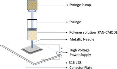
316 L SS contains 16–18% chromium which naturally prevents corrosion by forming a protective passive layer of chromic oxide film on its surface which truncates its ability to adhere external coatings. To increase the adhesiveness of 316 L SS towards the coating, the surface roughness of 316 L SS was increased by subjecting it to the electrochemical etching (EE) process. The EE process was carried out in the electrochemical workstation containing three-electrode system, 316 L SS as the working electrode, platinum wire as the cathode, Ag/AgCl2 as the reference electrode and 48% nitric acid as the electrolyte. A voltage of 2.2 V was applied for 90 seconds. After the electrochemical etching process, the etched sample was coated with nanofibers by electrospinning technique.The PAN-CMQD nanofibers were fabricated by blending the prepared CMQDs (1%) with PAN (8%) and electrospun at 20 kV electrospinning voltage, 0.5 ml h−1 flow rate, 20 cm needle-collector distance, 0.6 mm needle diameter. The electrospinning time was varied for 5 min, 10 min, 15 min, 20 min, 25 min and 30 min to determine the desired thickness of the coating.48 The PAN-CMQD nanofibers were deposited on 316 L SS and the coated sample was collected and characterized.
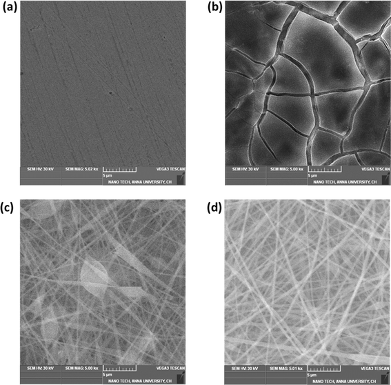
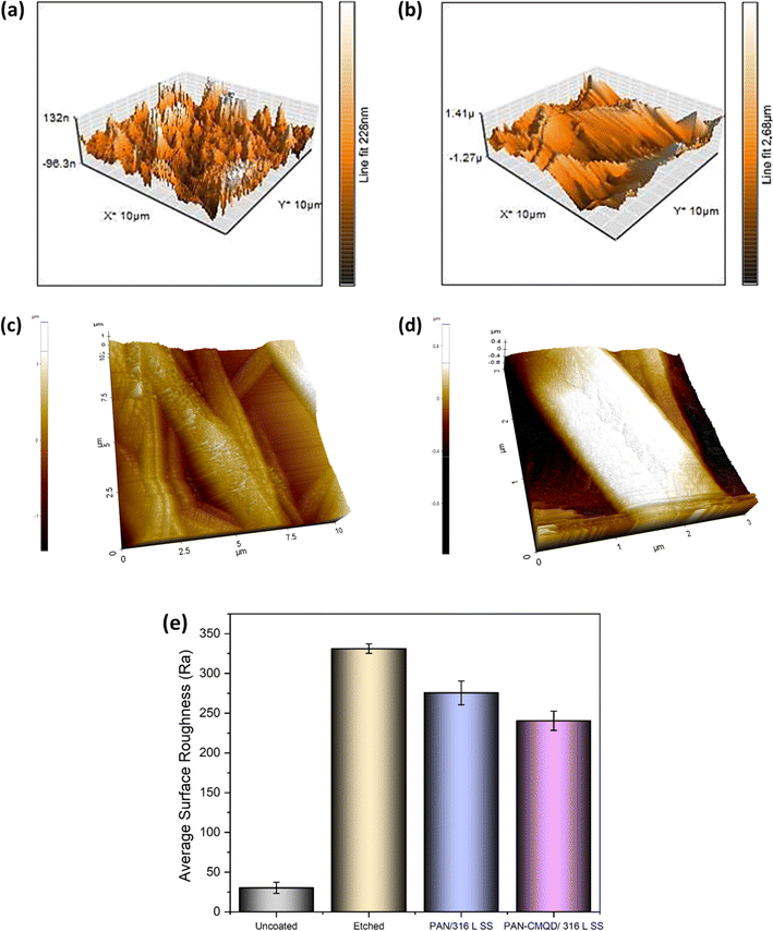
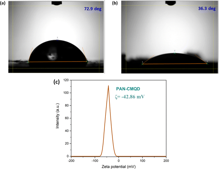
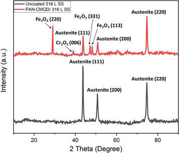
The process of deposition of nanofibers on 316 L SS is pictorially represented in Scheme 1. The PAN-CMQD coated 316 L SS was then characterized by scanning electron microscope (Tescan, Vega.3.SBU, Brno, Czech Republic) to understand the surface morphology of the nanofiber coating. The 316 L SS sample was cut into 1 cm × 1 cm dimension using wire cutting for SEM mounting. Since the nanofiber coating is non-conductive, in order to prevent charging under the electron beam, the nanofiber coated sample was sputtered with gold and palladium for 60 s. The surface roughness of the uncoated, etched and coated 316 L SS samples (1 cm × 1 cm) was determined using AFM (NaioAFM, Nanosurf AG Switzerland) at non-contact mode. Using a contact angle meter (DMe-211Plus, Kyowa, Japan) and the sessile drop technique, the surface wettability of the coated and uncoated samples was determined by calculating the water contact angle produced during the three-phase interphase. After placing the sample on the sample base, a tiny syringe was used to apply a drop of 5 μL water to the sample's surface. At room temperature, the contact angle (θ) of the water droplet's two surfaces was examined. For every sample, the experiment was run five times in order to get the average result. The functional groups present in both the uncoated and coated samples were validated using Fourier transform infrared spectroscopy (FTIR). The spectra of nanofiber were recorded using an FTIR spectrophotometer (JASCO FT/IR-6600, Tokyo, Japan) in transmittance mode in the range of 500 cm−1 to 4000 cm−1. X-Ray Diffraction (XRD) examination was performed using a Powder XRD System (PANalytical X'Pert Powder XRD System, United Kingdom) with a K-α source of 1.54 Å and a step size of 0.02. The diffraction patterns of uncoated and coated materials were recorded at a rate of 2° min−1 at room temperature (25 °C) with angles ranging from 10° to 90°.
2.4. Weight loss experiment
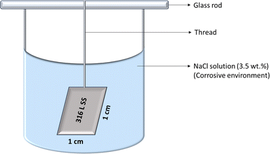
For the weight loss studies, 316 L SS was cut into 1 cm × 1 cm × 0.2 cm by wire cutting method and was cleaned by dipping it in acetone and ultrasonicating it for 10 min. The sample was then dried and the weight was recorded as the initial weight for uncoated sample. The weight loss studies for the coated and uncoated samples were done in triplicates and the weights were measured using 4-digit analytical balance. The coated samples were electrochemically etched before the electrospinning process. The coating process was done by electrospinning technique (1% dopant concentration and 0.5 ml h−1 flow rate) and the electrospinning time was varied for 5 min, 10 min, 15 min, 20 min, 25 min and 30 min and the weights of the coated samples were measured. The uncoated and the coated samples were then immersed separately in 3.5 wt% NaCl solution as the corrosive environment and the weights were noted on 7th day, 14th day, 21st day and 28th day. The weight loss experiment is represented in Scheme 2.The rate of corrosion (CR) was measured using eqn (1) where ΔW is the weight loss in mg (Wf − Wi), SA is the surface area of 316 L SS in cm2, ET is the time of exposure of the sample to the corrosive environment in hour and ρ is the density of 316 L SS (8 g cm−3).
| CR (mm year−1) = 87.6 × [ΔW/(SA × ET × ρ)] | (1) |
The corrosion inhibition efficiency (IE %) was calculated using the eqn (2) in which UCR and CCR are the corrosion rates (mm year−1) of the uncoated and coated 316 L SS respectively.
| IE (%) = [(UCR − CCR)/UCR] × 100 | (2) |
2.5. Electrochemical analysis
Potentiodynamic polarisation (PD) test and electrochemical impedance spectroscopy (EIS) test were the electrochemical techniques used to study the corrosion behaviour of the uncoated, etched, PAN, and PAN-CMQD coated 316 L SS specimens. The electrochemical workstation (CH Instruments, Electrochemical Analyzer, 604E, USA) was used to perform these electrochemical experiments. Since the most predominant ion in seawater that causes pitting corrosion in stainless steel is the chloride ion, the corrosion resistance of the developed coatings was evaluated using a 3.5 wt% NaCl solution to simulate corrosion in seawater. A three-electrode electrochemical cell was employed, with a platinum counter electrode, an Ag/AgCl reference electrode, and a 316 L SS specimen with a 1 cm2 contact surface area as the working electrode. At open circuit potential (OCP), the EIS measurements were carried out in the 10 kHz–10 mHz frequency range. The Zsimpwin programme was used to analyse the produced graphs in order to find the fitting parameters, and analogous electrical circuits were used to further clarify the relevance of the findings. Following an hour of immersion in the electrolyte, the specimens were subjected to potentiodynamic polarisation measurements at a scanning rate of 0.166 mV s−1 within the potential window of 0.8 V to 1.0 V. The PD plot was used to determine the anodic Tafel slope (βa), cathodic Tafel slope (βc), corrosion potential (Ecorr), and corrosion current density (Icorr). By using eqn (3), the inhibition efficiency (IE) was calculated from the PD plots, where ICcorr is the corrosion current density of processed 316 L SS and IUcorr is the corrosion current density of uncoated 316 L SS sample.49| IE (%) = (IUcorr − ICcorr)/IUcorr × 100 | (3) |
2.6. Long-term corrosion studies
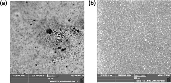
In order to assesses the effectiveness of corrosion protection and the durability of corrosion-resistant coatings on metals or alloys over time, EIS is a useful technique. 316 L SS samples that had been etched and coated with PAN-CMQD were examined for 30 days using 3.5 wt% NaCl solution. We track how the impedance of 316 L SS specimens that were coated with PAN-CMQD and those that were not coated varied during the 1st and 30th day. Polarisation and EIS experiments were conducted after 30 days, in which the pit morphologies on the 316 L SS specimens that were uncoated and PAN-CMQD coated were observed using SEM imaging.3. Results
3.1. Characterization of CMQD
The TEM micrograph of CMQD reveals spherical morphology with average size around 4.1 nm ± 1.8 as shown in Fig. 1(a). The zeta potential analysis showed that the surface charge of the CMQDs was −31.57 mV even after 8 months of its preparation, indicating their stability (Fig. 1(b)). The results of the Raman spectra proved that the structural integrity of the parent compound bulk CM was maintained in CMQD even after the ablation process, as evident from the similar peaks obtained for both CM and CMQD (Fig. 1(c)). The CMQDs show UV-Visible absorption spectrum (λabsorption = 417 nm; Eg = 2.5 eV) and the Pl emission spectrum (λemission = 520 nm) in the visible range of the electromagnetic spectrum as shown in Fig. 1(d).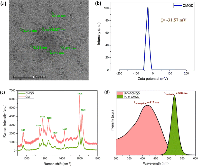 | ||
| Fig. 1 CMQD (a) TEM micrograph (b) zeta potential (c) Raman spectra (d) absorption and emission spectra. | ||
3.2. Optimization of PAN-CMQD coating by weight loss studies
The corrosion rate was determined by immersing 316 L SS (Uncoated 316 L SS, Coated 316 L SS (5 min, 10 min, 15 min, 20 min, 25 min and 30 min)) in 3.5 wt% NaCl environment for 7, 14, 21 and 28 days. The CR was calculated using the formula given in eqn (1). The recorded experimental data is tabulated in Table S1† and displayed in Fig. S1.† The results of the optimization study shows that the 20 min coated 316 L SS exhibits lowest CR (0.00035 ± 0.000033 mm year−1) and highest IE (98.41%) on the 28th day of immersion test compared to the other samples. The increase in the CR and the subsequent decrease in IE for the samples that were coated beyond 20 min of spinning time could be due to the detachment of the nanofiber coating from 316 L SS. Thus, it is inferred that the electrospinning time of 20 min is the optimum condition for obtaining coating with highest IE and low CR.3.3. Characterization of the optimized coating
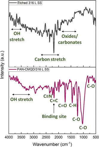
The binding interaction between PAN and CMQD was discussed in previously reported literature.43 It was reported that the PAN and CMQD were bound by hydrogen bonding between the C![[double bond, length as m-dash]](https://www.rsc.org/images/entities/char_e001.gif) O group of CMQD and C–H of acrylonitrile with a bond length of 2.2 Å.43,51 The FTIR spectrum of PAN-CMQD coated 316 L SS shows the presence of peaks typical to PAN such as those corresponding to C–H stretching (2800–3000 cm−1), C
O group of CMQD and C–H of acrylonitrile with a bond length of 2.2 Å.43,51 The FTIR spectrum of PAN-CMQD coated 316 L SS shows the presence of peaks typical to PAN such as those corresponding to C–H stretching (2800–3000 cm−1), C![[double bond, length as m-dash]](https://www.rsc.org/images/entities/char_e001.gif) O stretching (∼1700 cm−1), C–O stretching (1050–1250 cm−1), and C
O stretching (∼1700 cm−1), C–O stretching (1050–1250 cm−1), and C![[triple bond, length as m-dash]](https://www.rsc.org/images/entities/char_e002.gif) N stretch around 2240–2250 cm−1 which is the most prominent feature of the nitrile group of PAN.52,53 The presence of CMQD in PAN-CMQD coating is characterized by the presence of broad O–H stretching (3200–3600 cm−1) corresponds to the phenolic hydroxyl group attached to the aromatic rings, strong carbonyl stretching (C
N stretch around 2240–2250 cm−1 which is the most prominent feature of the nitrile group of PAN.52,53 The presence of CMQD in PAN-CMQD coating is characterized by the presence of broad O–H stretching (3200–3600 cm−1) corresponds to the phenolic hydroxyl group attached to the aromatic rings, strong carbonyl stretching (C![[double bond, length as m-dash]](https://www.rsc.org/images/entities/char_e001.gif) O) at 1625–1650 cm−1 of the diketone group, aromatic C
O) at 1625–1650 cm−1 of the diketone group, aromatic C![[double bond, length as m-dash]](https://www.rsc.org/images/entities/char_e001.gif) C (1500–1600 cm−1) vibrations, and C–O (1200–1300 cm−1) stretching peaks of the phenolic and enolic groups. The C–H bending and stretching vibrations around 1350–1450 cm−1 (aromatic and aliphatic), 2850–2950 cm−1 (aromatic), 2900 cm−1 (methyl group attached to aromatic ring), C
C (1500–1600 cm−1) vibrations, and C–O (1200–1300 cm−1) stretching peaks of the phenolic and enolic groups. The C–H bending and stretching vibrations around 1350–1450 cm−1 (aromatic and aliphatic), 2850–2950 cm−1 (aromatic), 2900 cm−1 (methyl group attached to aromatic ring), C![[double bond, length as m-dash]](https://www.rsc.org/images/entities/char_e001.gif) C stretch near 1600 cm−1 due to the conjugated double bonds present in the linear diketone structure of CMQD. These peaks confirm the presence of key functional groups such as phenolic hydroxyls, carbonyls, aromatic rings, and conjugated double bonds, which contribute to CMQDs electrochemical and anticorrosive properties.54,55
C stretch near 1600 cm−1 due to the conjugated double bonds present in the linear diketone structure of CMQD. These peaks confirm the presence of key functional groups such as phenolic hydroxyls, carbonyls, aromatic rings, and conjugated double bonds, which contribute to CMQDs electrochemical and anticorrosive properties.54,55
Further, it could be observed that the peak intensity of the uncoated 316 L SS at 2185 cm−1 corresponding to C![[triple bond, length as m-dash]](https://www.rsc.org/images/entities/char_e002.gif) C decreased in the PAN-CMQD coated 316 L SS sample, which could be one of the possible major binding sites of interaction between the 316 L SS surface and the coating. The presence of characteristic peaks of PAN and CMQD in PAN-CMQD coated 316 L SS confirms the successful adhesion of PAN-CMQD coating on 316 L SS.
C decreased in the PAN-CMQD coated 316 L SS sample, which could be one of the possible major binding sites of interaction between the 316 L SS surface and the coating. The presence of characteristic peaks of PAN and CMQD in PAN-CMQD coated 316 L SS confirms the successful adhesion of PAN-CMQD coating on 316 L SS.
3.4. Electrochemical analysis
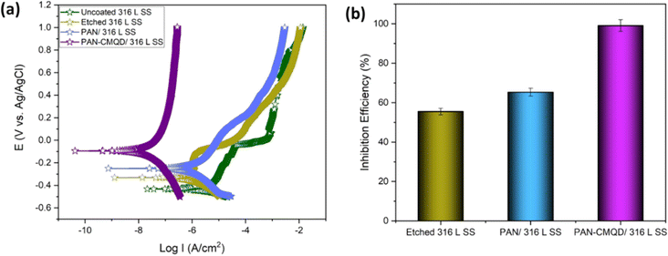
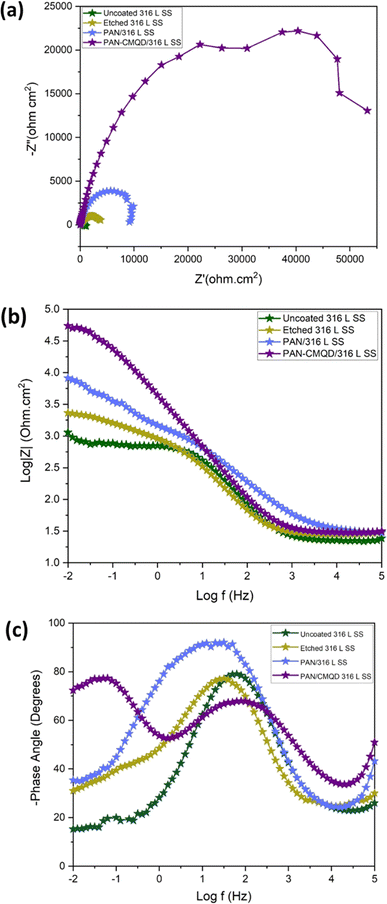
From the weight loss studies, the electrospinning time of 20 min was determined to be the optimal condition. The electrochemical analysis was performed for 20 min PAN-CMQD coated sample and was compared with uncoated, etched and pristine PAN coated sample (20 min spinning time) in same conditions. The results of the PD plot and EIS plot were analysed to determine the anticorrosive performance of PAN-CMQD coated 316 L SS.From Fig. 7(a), it could be observed that the passive current density of uncoated is −4.9133 × 10⁻⁶ A cm−2 and the range of passivation is from −0.39 V vs. Ag/AgCl to −0.02 V vs. Ag/AgCl. However, for the nanofiber coatings, passive current density was less as −1.904 × 10⁻⁶ A cm−2, −4.0588 × 10⁻⁸ A cm−2 and the range of passivation was from −0.3 V vs. Ag/AgCl up to 1 V vs. Ag/AgCl, −0.06 V vs. Ag/AgCl up to 1 V vs. Ag/AgCl for pristine PAN, optimized PAN-CMQD coated specimens respectively. The passive range of CMQD reinforced PAN coated specimen was very wide and even at 1 V it did not start pitting, indicating superior corrosion resistance and passivity. Jang et al. reported that after electrochemical etching process, the etched surface showed an increased amount of Cr and Mo content and also demonstrated that chromium oxide (Cr2O3) is the primary contributor to corrosion resistance of etched surface of stainless steel.39 In our study, the Icorr values of PAN, optimized PAN-CMQD coated 316 L SS specimens showed significantly lower values as compared to the uncoated and etched surface. Compared to PAN coated specimen, CMQD reinforced PAN coated specimens showed a two-order decrease in corrosion current density. This shows that PAN-CMQD possess good corrosion inhibition property.
From the PD plot, the inhibition efficiency (IE) was calculated using eqn (3) and shown in Fig. 7(b). The IE of PAN-CMQD/316 L SS, PAN/316 L SS and etched 316 L SS were 99.18%, 61.24%, 54.72% respectively compared to uncoated 316 L SS. The IE of PAN-CMQD/316 L SS.
The Bode plot (Fig. 8(b)) shows higher impedance modulus values for the treated specimens (etched 316 L SS < PAN/316 L SS < optimized PAN-CMQD/316 L SS) compared to the untreated specimen (uncoated 316 L SS). The higher impedance modulus value for the optimized PAN-CMQD/316 L SS shows that they possess higher resistance for electrical transfer compared to the other specimens.60
The Phase plot (Fig. 8(c)) shows higher phase angle for the treated specimens (etched 316 L SS < PAN/316 L SS < optimized PAN-CMQD/316 L SS) compared to the untreated specimen (uncoated 316 L SS). In the uncoated 316 L SS, the phase angle in the low-frequency region reached as low as −15° depicting the inductive behavior. The etched 316 L SS and PAN/316 L SS exhibited a phase angle of −30° and −35° respectively, in the low-frequency region which is higher than the untreated specimen. The optimized PAN-CMQD/316 L SS exhibited a phase angle of −72° in the low frequency region. Thus, the higher phase angle of −72° in the low frequency region observed for the optimized PAN-CMQD/316 L SS shows higher resistance to corrosion thereby protecting the substrate from the penetration of corrosive ions which is in accordance with the trend observed in the Nyquist and Bode plot.61
The high phase angles for optimized PAN-CMQD in the high frequency region of 105 Hz illustrates the better homogeneity of coated surfaces in comparison to the passive oxide layer present on uncoated 316 L SS. It has been reported in literature that the high phase angle in high frequency region (105 Hz) suggests homogeneous and dense coating in addition to good corrosion protection.62
The proposed electrical equivalent circuits (EECs) for the uncoated 316 L SS, etched 316 L SS, PAN/316 L SS and optimized PAN-CMQD/316 L SS were determined with an equivalent circuit (EC) by ZSmipwin software 3.21 (Scheme 3) and the values are given in Table S3.† The electrochemical response of the uncoated 316 L SS and etched 316 L SS in 3.5 wt% NaCl were modelled as shown in Scheme 3(a). The resistance offered by the electrolyte (Rs) is associated with the high frequency behavior of the electrochemical system. The charge distribution due to non-Faradic process (constant phase element (Qdl)) and Faradaic processes (charge transfer resistance (Rct)) at the electrolyte–electrode interface is quantified by the impedance measurement at low and medium frequency region.
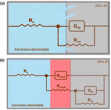 | ||
| Scheme 3 Electrical equivalent circuit (a) uncoated 316 L SS and etched 316 L SS, (b) PAN coated 316 L SS and PAN-CMQD coated 316 L SS. | ||
Qdl is associated with the inhomogeneous charge distribution occurring at the oxide–electrolyte interface and also depends on the dielectric characteristics of the oxide film and the nature of electrolyte at the oxide-electrolyte interface.38 The electrochemical response of the coated specimens (PAN/316 L SS and optimized PAN-CMQD/316 L SS) in 3.5 wt% NaCl was modelled as shown in Scheme 3(b). The electrical circuit of this model is similar to the model for the untreated specimen, except that it contains another time constant constituted of constant phase components that stand in for the coating resistance (Rcoat) at the electrolyte-coating surface interface and the coating capacitance (Qcoat) representing the dielectric characteristics of the coating.
The EIS plots of uncoated and coated specimens after 30 days of exposure in NaCl are shown in Fig. 9(b–f). The Nyquist plots for 1st day and 30th day of uncoated and PAN-CMQD coated 316 L SS specimens are shown in Fig. 9(b) and (c) respectively. From Fig. 9(b), it was observed that the diameter of the semicircle loop of 30th day sample decreased compared to 1st day sample, indicating that the corrosion increases with long-term exposure. This occurs as a result of the passive film rupturing and stable pits forming due to the buildup of metallic chlorides in it. Fig. 9(c) shows Nyquist plots of PAN-CMQD coated 316 L SS on 1st and 30th day of exposure that showed no significant change in the semicircle loop of impedance plot of 30th day sample as in the case of 1st day exposure sample. Even after 30 days of exposure, the large diameter of the semicircle capacitive loop in the PAN-CMQD coated 316 L SS demonstrates the superior corrosion resistance of the PAN-CMQD coating.64
The Bode plots of uncoated and PAN-CMQD coated 316 L SS sample after 30 days exposure in corrosive environment is shown in Fig. 9(d). The impedance modulus values of the PAN-CMQD coated 316 L SS sample remains the same even after 30 days of corrosion environment indicating the long-term corrosion resistance of PAN-CMQD coated 316 L SS. The Bode plot of uncoated 316 L SS showed significant variation in the impedance modulus values of the 1st day and 30th day immersion of uncoated 316 L SS. This variation in the impedance modulus of the long term exposed uncoated sample could be due to the disruption of the passive layer caused by the corrosive environment leading to pit formation in the uncoated sample.65
The phase angle plot of 1st day and 30th day exposed uncoated and coated sample is shown in Fig. 9(e) and Table S4.† The values of phase angle of uncoated and coated samples at low frequency region (LFR) and high frequency region (HFR) are shown in Fig. 9(f). The Fig. 9(e), shows no significant change in the phase angle of PAN-CMQD coated specimen at HFR and LFR, proving the better corrosion performance of PAN-CMQD coating even after 30 days of exposure. On the other hand, there is considerable variation in the phase angle of uncoated sample at LFR and HFR after 30 days of exposure. This is because of the breakdown of the passive layer in corrosive environment with long term exposure. Further from these results, it could be inferred that the coating remains intact in corrosive electrolyte due to effective adhesion of the nanofiber coating on the surface of etched 316 L SS. The higher phase angle of the coated surface even after 30 days of exposure (θ = −72°) as depicted in Fig. 9(f) indicates the capacitive behavior of PAN-CMQD coating that provides good anticorrosive performance on 316 L SS.
4. Corrosion inhibition mechanism
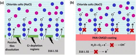
A combination of microscopy (SEM) and spectroscopy (EIS) is often the most effective approach to determine the mechanism of the corrosion phenomena. Microscopy provides insights into the physical damage and structural changes, while spectroscopy reveals the chemical transformations and electrochemical reactions.Generally, corrosion occurs due to the electrochemical reactions taking place between the metal surface and environment. 316 L SS alloy is designed to naturally overcome corrosion by forming a protective oxide layer called passive film that acts as a barrier, preventing electrochemical reactions between the metal–environment interface. However, under certain conditions especially prolonged exposure to chloride ions in marine environment could accelerate the corrosion of 316 L SS. The plausible corrosion inhibition mechanism of 316 L SS by PAN-CMQD coated samples could be explained based on the experimental data obtained through the electrochemical analysis. The results showed increase in inhibition efficiency (99.18%), higher impedance modulus and phase angle. The increase in corrosion inhibition efficiency indicates that PAN-CMQD served as effective coating on 316 L SS preventing the corrosion of metal.
The corrosion inhibition behaviour could be attributed to the functional groups of CMQD such as phenolic hydroxyl (–OH), carboxylic (–COOH) and carbonyl groups (C![[double bond, length as m-dash]](https://www.rsc.org/images/entities/char_e001.gif) O) that facilitate effective adsorption on metal surface and also the methoxy group (O–CH3) makes the coating more reliable through lone pair of O2 atoms.36,66,67 Through effective adsorption on the metal surface, PAN-CMQD acts as a protective layer against corrosion. By acting as a barrier, this protective layer prevents the metal and the corrosive electrolyte NaCl from interaction. Furthermore, the nanofibers' large surface area offers more active sites, enhancing the coating's anticorrosion performance. Moreover, PAN-CMQD coating (ζ = −42.86 mV) would rebuff the entry of Cl− ions by electrostatic repulsion due to their negative surface charges. These factors contribute to enhance coatings' corrosion resistance behaviour.68–72
O) that facilitate effective adsorption on metal surface and also the methoxy group (O–CH3) makes the coating more reliable through lone pair of O2 atoms.36,66,67 Through effective adsorption on the metal surface, PAN-CMQD acts as a protective layer against corrosion. By acting as a barrier, this protective layer prevents the metal and the corrosive electrolyte NaCl from interaction. Furthermore, the nanofibers' large surface area offers more active sites, enhancing the coating's anticorrosion performance. Moreover, PAN-CMQD coating (ζ = −42.86 mV) would rebuff the entry of Cl− ions by electrostatic repulsion due to their negative surface charges. These factors contribute to enhance coatings' corrosion resistance behaviour.68–72
The possible anticorrosion mechanism of PAN-CMQD coated 316 L SS is pictorially represented in Scheme 4. The Scheme 4(b) describes the protective role of the PAN-CMQD coating that serves as a barrier preventing the Cl-attack on 316 L SS. On the other hand, in the uncoated sample, the metal surface is prone to corrosion attack due to the dissolution of the passive oxide layer, allowing the penetration of the Cl− ions into the metal surface, leading to e− loss from the metal surface, causing corrosion. In case of PAN-CMQD/316 L SS, there is no loss of e− from 316 L SS's surface and hence it could be stated that PAN-CMQD could effectively act as a barrier coating to prevent corrosion of 316 L SS.
5. Discussion
The anticorrosion performance of PAN-CMQD/316 L SS exhibiting IE of 99.18% compared to the state of art literature is tabulated in Table S5.† The enhanced anticorrosion performance of PAN-CMQD/316 L SS could be attributed to its unique properties such as oxygen containing functional groups (–OH, –COOH, C![[double bond, length as m-dash]](https://www.rsc.org/images/entities/char_e001.gif) O, O–CH3) along with improved electrochemical stability offered by the quantum size of CMQD, coating's overall negative surface charge (ζ = −42.86 mV), physical features of the nanofibers (high mechanical strength, chemical inhibition offered by PAN coupled with high surface area of the nanofiber coating with uniform distribution) that served as excellent barrier against the entry of the corrosive agent Cl− ions. The results of the electrochemical analysis revealed that PAN-CMQD exhibited high impedance, low corrosion current density and high charge transfer resistance. It could be comprehended from the previously reported literature on nanofiber based anticorrosive coatings that the IE exhibited by PAN-CMQD is on par with the other reported nanofiber coating involving either metal-based additives or complex coating technique. However, the results of this investigation on the anticorrosive performance of PAN-CMQD nanofiber coating evaluated on 316 L SS may not directly translate to other materials without variation. The results will depend on several factors related to the substrate material such as electrochemical properties (different metals and alloys have different electrochemical properties, including corrosion potential and resistance and might behave differently under the same coating), surface interaction (the surface energy, roughness, and chemical composition of the substrate can affect coating adhesion and consequently its anticorrosion performance), passivation behaviour (some materials like stainless steel can form a natural passive oxide layer, while others might rely entirely on the coating for protection). All of these factors would influence how well the coating could perform in inhibiting corrosion of different materials. In addition to this, 316 L SS is a relatively corrosion-resistant material due to its high chromium and molybdenum content. The PAN-CMQD coating enhances its anticorrosion properties, but a more corrosion-prone material (such as carbon steel) may still experience some degree of corrosion despite the coating. Hence, testing the coating on different substrates will be essential to verify its universal effectiveness. The unique feature of this research work is the use of natural ecofriendly non-toxic bioactive compound CMQD as the additive for nanofiber coating fabrication. Furthermore, the electrospinning technique would serve as a flexible and effective approach to develop advanced anticorrosive coatings with tunable properties for protecting metal substrates in various industrial applications. However, PAN-CMQD anticorrosive coating's general applicability across industries will depend on several factors depending on the type of metallic substrate, industrial requirements and the environmental factors for improved functionality of the products manufactured. Extending this technology to other metallic materials like carbon steel, aluminium, and copper could be beneficial, but testing and optimization would be required to ensure compatibility and performance in specific environments.
O, O–CH3) along with improved electrochemical stability offered by the quantum size of CMQD, coating's overall negative surface charge (ζ = −42.86 mV), physical features of the nanofibers (high mechanical strength, chemical inhibition offered by PAN coupled with high surface area of the nanofiber coating with uniform distribution) that served as excellent barrier against the entry of the corrosive agent Cl− ions. The results of the electrochemical analysis revealed that PAN-CMQD exhibited high impedance, low corrosion current density and high charge transfer resistance. It could be comprehended from the previously reported literature on nanofiber based anticorrosive coatings that the IE exhibited by PAN-CMQD is on par with the other reported nanofiber coating involving either metal-based additives or complex coating technique. However, the results of this investigation on the anticorrosive performance of PAN-CMQD nanofiber coating evaluated on 316 L SS may not directly translate to other materials without variation. The results will depend on several factors related to the substrate material such as electrochemical properties (different metals and alloys have different electrochemical properties, including corrosion potential and resistance and might behave differently under the same coating), surface interaction (the surface energy, roughness, and chemical composition of the substrate can affect coating adhesion and consequently its anticorrosion performance), passivation behaviour (some materials like stainless steel can form a natural passive oxide layer, while others might rely entirely on the coating for protection). All of these factors would influence how well the coating could perform in inhibiting corrosion of different materials. In addition to this, 316 L SS is a relatively corrosion-resistant material due to its high chromium and molybdenum content. The PAN-CMQD coating enhances its anticorrosion properties, but a more corrosion-prone material (such as carbon steel) may still experience some degree of corrosion despite the coating. Hence, testing the coating on different substrates will be essential to verify its universal effectiveness. The unique feature of this research work is the use of natural ecofriendly non-toxic bioactive compound CMQD as the additive for nanofiber coating fabrication. Furthermore, the electrospinning technique would serve as a flexible and effective approach to develop advanced anticorrosive coatings with tunable properties for protecting metal substrates in various industrial applications. However, PAN-CMQD anticorrosive coating's general applicability across industries will depend on several factors depending on the type of metallic substrate, industrial requirements and the environmental factors for improved functionality of the products manufactured. Extending this technology to other metallic materials like carbon steel, aluminium, and copper could be beneficial, but testing and optimization would be required to ensure compatibility and performance in specific environments.
6. Conclusions
In this work, polyacrylonitrile was modified by blending with curcumin quantum dots to fabricate anticorrosive nanofibrous coating on 316 L SS through electrospinning technique. The CMQDs prepared by laser ablation method possessed high surface area owing to their quantum size (4.1 nm ± 1.8) and also showed good stability (ζ = −31.57 mV). The CMQDs were then blended with PAN and deposited on 316 L SS as nanofibrous coating which was optimized by weight loss studies that resulted in 20 min of electrospinning time as the optimized condition. The optimized PAN-CMQD coating showed lower surface roughness (Ra = 240.47 ± 12), lower contact angle (CA = 36.3°), strong anionic nature (ζ = −42.86 mV) and also indicate smooth and uniform distribution of nanofibers on 316 L SS. The optimized PAN-CMQD coated samples were then examined to assess their corrosion inhibition characteristics in 3.5 wt% NaCl electrolyte as the corrosion environment by EIS and PD analysis. The results obtained from EIS and PD plots were compared with the uncoated, etched and pristine PAN coated samples. The electrochemical analysis revealed that PAN-CMQD coated sample exhibited excellent corrosion resistance with an inhibition efficiency of 99.18% and 2-order decrease in corrosion current density compared to other samples. The samples were then subjected to long-term studies by performing the electrochemical analysis for the samples before and after immersion in corrosive electrolyte for 30 days. The results showed that PAN-CMQD coated samples did not show significant changes in Icorr and Ecorr values, proving the longevity of the coating. The morphology of the uncoated and PAN-CMQD coated samples were visualized by SEM imaging which showed no pit formation for PAN-CMQD coated sample. The results of this study would lay the foundation for developing anticorrosive coatings using renewable ecofriendly bioactive compounds like curcumin and would also serve as a reference for the development of PAN based anticorrosive nanofibrous coating on 316 L SS through electrospinning technique.Data availability
The data supporting this article have been included as part of the ESI.†Author contributions
Iffath Badsha: conceptualization, methodology and writing-original draft. Renjith Kumar Rasal: formal analysis, data curation and writing-review & editing. Wirach Taweepreda: visualization and investigation. Arthanareeswaran Gangasalam: software and validation. Thiyagarajan Devasena: resources and supervision. All authors have read and agreed to the published version of the manuscript.Conflicts of interest
The authors declare no conflicts of interest.Acknowledgements
This research was funded by All India Council for Technical Education, S2022311 and the APC was funded by Collaborative Research Grant of Fiscal Year 2025, Prince of Songkla University.References
- S. Sen-Britain, S. Cho, S. Kang, Z. Qi, S. Khairallah, D. Rosas, V. Som, T. T. Li, Q. S. Roger, M. Y. Morris and B. C. Wood, Nat. Commun., 2024, 15, 867, DOI:10.1038/s41467-024-45120-6.
- P. Ebrahimzadeh, L. B. Peral, R. González-Martínez, E. Mardaras and I. Fernández-Pariente, Corros. Sci., 2024, 231, 111988, DOI:10.1016/j.corsci.2024.111988.
- R. R. Kumar, T. Devasena and M. Abeens, Optik, 2023, 276, 170654, DOI:10.1016/j.ijleo.2023.170654.
- Y. Pan, B. Sun, H. Chen, Z. Liu, W. Dai, X. Yang, W. Yang, Y. Deng and X. Li, Corros. Sci., 2024, 231, 111978, DOI:10.1016/j.corsci.2024.111978.
- C. L. De-Canonville, M. Minissale, F. Romero-Lairado, E. Salomon, G. Giacometti, T. Angot, L. Bisson and R. Gallais, Mater. Today Commun., 2023, 36, 106865, DOI:10.1016/j.mtcomm.2023.106865.
- Y. Ren, Y. Li, Z. Kang, X. Zhang, S. Wu, J. Shen and G. A. Zhou, Nanomaterials, 2023, 13, 367, DOI:10.3390/nano13020367.
- H. Wan, T. Zhang, J. Wang, Z. Rao, Y. Zhang, G. Li, T. Gu and H. Liu, Bioelectrochemistry, 2023, 150, 108367, DOI:10.1016/j.bioelechem.2023.108367.
- L. B. Coelho, D. Torres, M. Bernal, G. M. Paldino, G. Bontempi and J. Ustarroz, Corros. Sci., 2023, 217, 111104, DOI:10.1016/j.corsci.2023.111104.
- R. J. Wood and P. Lu, Coatings, 2024, 14, 99, DOI:10.3390/coatings14010099.
- Y. Jia and K. Zhang, RSC Adv., 2024, 14, 11758–11770, 10.1039/D4RA00522H.
- V. S. Aigbodion, A. A. Alayyaf and C. J. Ozoude, RSC Adv., 2024, 14, 24152–24164, 10.1039/D4RA04076G.
- J. L. de Lacalle, D. Minudri, M. L. Picchio, A. Gallastegui, D. Mantione, M. Forsyth and D. Mecerreyes, RSC Sustainability, 2024, 2, 1809–1818, 10.1039/D4SU00117F.
- L. Shao, N. Xue, W. Li, S. Liu, Z. Tu, Y. Chen, J. Zhang, S. Dai, Q. Liu, X. Shi and T. Wang, Processes, 2023, 11, 959, DOI:10.3390/pr11030959.
- B. Meng, J. Wang, M. Chen, S. Zhu and F. Wang, Corros. Sci., 2023, 225, 111591, DOI:10.1016/j.corsci.2023.111591.
- M. H. Qureshi, A. Farooq, M. Wasim and K. M. Deen, Mater. Res. Express, 2024, 11, 016508, DOI:10.1088/2053-1591/ad1b07.
- Y. Wu, H. Wu, Y. Zhao, G. Jiang, J. Shi, C. Guo, P. Liu and Z. Jin, Mater. Today Nano, 2023, 24, 100429, DOI:10.1016/j.mtnano.2023.100429.
- Z. Cao, X. Liang, S. Luo, J. Song, C. Pu, Z. Pang and W. He, Vacuum, 2024, 222, 112995, DOI:10.1016/j.vacuum.2024.112995.
- Y. T. Li, X. Jiang, X. T. Wang and Y. X. Leng, Scr. Mater., 2024, 238, 115763, DOI:10.1016/j.scriptamat.2023.115763.
- Y. T. Li, X. M. Chen, X. K. Zeng, M. Liu, X. Jiang and Y. X. Leng, J. Mater. Sci. Technol., 2024, 173, 20–30, DOI:10.1016/j.jmst.2023.05.082.
- J. Song, M. Kim and H. Lee, Polymers, 2020, 12, 1386, DOI:10.3390/polym12061386.
- H. Zhao, G. Zhao, F. Liu, T. Xiang, J. Zhou and L. Li, J. Colloid Interface Sci., 2024, 666, 131–140, DOI:10.1016/j.jcis.2024.04.029.
- Z. Li Yang, X. Wang, L. Li and Z. Chen, Chin. J. Catal., 2024, 59, 237–249, DOI:10.1016/S1872-2067(23)64566-8.
- Y. Wang, Y. Xu, W. Zhai, Z. Zhang, Y. Liu, S. Cheng and H. Zhang, Nat. Commun., 2022, 13, 5056, DOI:10.1038/s41467-022-32804-0.
- Y. Wang, W. Zhai, J. Li, H. Liu, C. Li and J. Li, Tribol. Int., 2023, 188, 108891, DOI:10.1016/j.triboint.2023.108891.
- P. J. Rivero, D. M. Redin and R. J. Rodríguez, Metals, 2020, 10, 350, DOI:10.3390/met10030350.
- Z. Chen, Z. Zhang, Y. Ouyang, Y. Chen, X. Yin, Y. Liu, H. Ying and W. Yang, Colloids Surf., A, 2023, 662, 131041, DOI:10.1016/j.colsurfa.2023.131041.
- P. Jain, B. Patidar and J. Bhawsar, J. Bio- Tribo-Corros., 2020, 6, 43, DOI:10.1007/s40735-020-00335-0.
- P. J. Rivero, D. Yurrita, C. Berlanga, J. F. Palacio and R. Rodríguez, Coatings, 2018, 8, 300, DOI:10.3390/coatings8090300.
- X. Zhao, S. Yuan, Z. Jin, Q. Zhu, M. Zheng, Q. Jiang, H. Song and J. Duan, Prog. Org. Coat., 2020, 149, 105893, DOI:10.1016/j.porgcoat.2020.105893.
- S. He, Y. Gao, X. Gong, C. Wu and H. Cen, J. Coat. Technol. Res., 2023, 20, 819–841, DOI:10.1007/s11998-022-00735-6.
- A. Trentin, A. Pakseresht, A. Duran, Y. Castro and D. Galusek, Polymers, 2022, 14, 2306, DOI:10.3390/polym14122306.
- K. Sukhareva, V. Chernetsov and I. A. Burmistrov, Polymers, 2024, 16, 809, DOI:10.3390/polym16060809.
- V. Thavasi, G. Singh and S. Ramakrishna, Energy Environ. Sci., 2008, 1, 205–221, 10.1039/B809074M.
- I. Karbownik, M. Fiedot, O. Rac, P. Suchorska-Woźniak, T. Rybicki and H. Teterycz, Polymer, 2015, 75, 97–108, DOI:10.1016/j.polymer.2015.08.015.
- E. H. Ali, J. A. Naser, Z. W. Ahmed and T. A. Himdan, J. Renewable Mater., 2021, 9, 1927–1939, DOI:10.32604/jrm.2021.015624.
- A. Miralrio and V. A. Espinoza, Processes, 2020, 8, 942, DOI:10.3390/pr8080942.
- R. Renjithkumar, B. Iffath and T. Devasena, Dig. J. Nanomater. Biostructures, 2023, 18, 377–388, DOI:10.15251/DJNB.2023.181.377.
- N. Ashwini, R. Dileep and S. Ranganatha, Phys. Chem. Res., 2023, 11, 825–835, DOI:10.22036/PCR.2022.362856.2199.
- X. Yuan, S. Dong, Q. Zheng, W. Yang and T. Huang, J. Chem. Eng., 2020, 389, 124296, DOI:10.1016/j.cej.2020.124296.
- M. Edraki, I. M. Moghadam, M. B. Keivani and M. Fekri, Eurasian chem. commun., 2019, 1, 228–241, DOI:10.30473/icc.2018.42617.1486.
- K. A. Saleh and M. K. Mohammed, Int. J. ChemTech Res., 2017, 10, 515–529, DOI:10.1108/ACMM-06-2017-1805.
- S. Rajendran, S. Shanmugapriya, T. Rajalakshmi and A. J. Amal Raj, Corros. Sci., 2005, 61, 685–692, DOI:10.5006/1.3278203.
- I. H. Farooqi, A. Hussain, P. A. Saini and M. A. Quraishi, Anti-Corros. Mater. Methods, 1999, 46, 328–331, DOI:10.1108/00035599910295508.
- A. S. Yaro and K. F. Talib, Iraqi J. Chem. Pet. Eng., 2014, 15, 9–18, DOI:10.31699/IJCPE.2014.3.2.
- Y. Deng, L. Xia, G. L. Song, Y. Zhao, Y. Zhang, Y. Xu and D. Zheng, Composites, Part B, 2021, 225, 109263, DOI:10.1016/j.compositesb.2021.109263.
- B. Iffath, K. R. Renjith, G. Arthanareeswaran and T. Devasena, J. Water Process Eng., 2024, 60, 105251, DOI:10.1016/j.jwpe.2024.105251.
- B. Iffath, R. Renjithkumar and T. Devasena, Dig. J. Nanomater. Biostructures, 2023, 18, 183–193, DOI:10.15251/DJNB.2023.181.183.
- K. R. Renjith, B. Iffath, T. Devasena, R. Nallaiyan, S. Manju and N. Gobi, J. Ind. Eng. Chem., 2024, 138, 208–236, DOI:10.1016/j.jiec.2024.03.055.
- A. Balakrishnan, G. Jena, R. Pongachira George and J. Philip, Environ. Sci. Pollut. Res., 2021, 28, 7404–7422, DOI:10.1007/s11356-020-11068-5.
- Y. Zhang, X. Wang, C. Wang, J. Liu, H. Zhai, B. Liu, X. Zhao and D. Fang, RSC Adv., 2018, 8, 35150–35156, 10.1039/C8RA06059B.
- P. Govindaraj, B. Kandasubramanian and K. M. Kodam, Mater. Chem. Phys., 2014, 147, 934–941, DOI:10.1016/j.matchemphys.2014.06.040.
- S. Patel and G. Hota, J. Environ. Chem. Eng., 2018, 6, 5301–5310, DOI:10.1016/j.jece.2018.08.013.
- V. S. Naragund and P. K. Panda, J. Mater. Sci. Appl., 2018, 4, 68–74, DOI:10.1007/s42247-022-00350-6.
- R. S. Nair, A. Morris, N. Billa and C. O. Leong, AAPS PharmSciTech, 2019, 20, 69, DOI:10.1208/s12249-018-1279-6.
- H. Rachmawati, Y. L. Yanda, A. Rahma and N. Mase, Sci. Pharm., 2016, 84, 191, DOI:10.3797/scipharm.ISP.2015.10.
- Y. Cai, X. Luo, M. Maclean, Y. Qin, M. Duxbury and F. Ding, J. Mater. Process. Technol., 2019, 271, 249–260, DOI:10.1016/j.jmatprotec.2019.04.012.
- M. Dadfar, M. H. Fathi, F. Karimzadeh, M. R. Dadfar and A. Saatchi, Mater. Lett., 2007, 61, 2343–2346, DOI:10.1016/j.matlet.2006.09.008.
- G. Jena, B. Anandkumar, S. Sofia, R. P. George and J. Philip, Surf. Coat. Technol., 2020, 402, 126295, DOI:10.1016/j.surfcoat.2020.126295.
- Y. Jang, W. T. Choi, C. T. Johnson, A. J. García, P. M. Singh, V. Breedveld, D. W. Hess and J. A. Champion, ACS Biomater. Sci. Eng., 2018, 4, 90–97, DOI:10.1021/acsbiomaterials.7b00544.
- G. Jena, S. C. Vanithakumari, S. R. Polaki, R. P. George, J. Philip and G. Amarendra, J. Coat. Technol. Res., 2019, 16, 1317–1335, DOI:10.1007/s11998-019-00213-6.
- M. Kalaiyarasan, S. Pugalmani and N. Rajendran, J. Magnesium Alloys, 2023, 11, 614–628, DOI:10.1016/j.jma.2022.05.003.
- B. Ramezanzadeh, A. Ahmadi and M. J. C. S. Mahdavian, Corros. Sci., 2016, 109, 182–205, DOI:10.1016/j.corsci.2016.04.004.
- L. B. Coelho, S. Kossman, A. Mejias, X. Noirfalise, A. Montagne, G. A. Van, M. Poorteman and M. G. Olivier, Surf. Coat. Technol., 2020, 382, 125175, DOI:10.1016/j.surfcoat.2019.125175.
- P. Kannan, R. Rajeev, A. Varghese and N. Rajendran, J. Appl. Electrochem., 2022, 52, 1659–1674, DOI:10.1007/s10800-022-01741-7.
- P. P. Katta and R. Nalliyan, Surf. Coat. Technol., 2019, 375, 715–726, DOI:10.1016/j.surfcoat.2019.07.042.
- A. El-Faham, S. M. Osman, H. A. Al-Lohedan and G. A. El-Mahdy, Molecules, 2016, 21, 714, DOI:10.3390/molecules21060714.
- N. Palaniappan, I. Cole, F. Caballero-Briones, S. Manickam, K. J. Thomas and D. Santos, RSC Adv., 2020, 10, 5399–5411, 10.1039/C9RA08971C.
- Y. Zhao, M. Huang, Z. Gao, H. He, Y. Chen, F. He, Y. Lin, B. Yan and S. Chen, Polym. Eng. Sci., 2023, 63, 1613–1622, DOI:10.1002/pen.26310.
- M. G. K. AlFalah, E. Kamberli, A. H. Abbar, F. Kandemirli and M. Saracoglu, Surf. Interfaces, 2020, 21, 100760, DOI:10.1016/j.surfin.2020.100760.
- A. R. Siddiqui, R. Maurya, P. K. Katiyar and K. Balani, Surf. Coat. Technol., 2020, 404, 126421, DOI:10.1016/j.surfcoat.2020.126421.
- M. Es-Saheb, A. A. Elzatahry, E. S. M. Sherif, A. S. Alkaraki and E. R. Kenawy, Int. J. Electrochem. Sci., 2012, 7, 5962–5976, DOI:10.1016/S1452-3981(23)19454-5.
- S. Gaballah, N. Shehata, M. Shaaban, S. Nosier, A. Hefnawy, A. Hamed and E. Samir, Int. J. Electrochem. Sci., 2017, 12, 1094–1105, DOI:10.20964/2017.02.05.
Footnote |
| † Electronic supplementary information (ESI) available: Fig. S1: Inhibition efficiency from weight loss studies; Fig. S2: Fiber diameter of pristine PAN nanofiber coated 316 L SS and its corresponding histogram; Fig. S3: Fiber diameter of PAN-CMQD nanofiber coated 316 L SS and its corresponding histogram. Table S1: Experimental data of weight loss study; Table S2: The electrochemical parameters obtained from PD plot; Table S3: EIS parameters obtained from ZSmipwin software for uncoated 316 L SS, etched 316 L SS, PAN coated 316 L SS and PAN-CMQD coated 316 L SS; Table S4: Phase angle value of HFR and LFR for the uncoated and coated 316 L SS for the 1st and 30th day of immersion in corrosive electrolyte. Table S5: Comparison with the current state of art with respect to nanofiber based anticorrosive coatings. See DOI: https://doi.org/10.1039/d4ra05075d |
| This journal is © The Royal Society of Chemistry 2024 |

