 Open Access Article
A flexible solid-state asymmetric supercapacitor device comprising cobalt hydroxide and biomass-derived porous carbon†
Rajeshvari Samatbhai Karmur‡
a,
Debika Gogoi‡a,
Manash R. Das bc and
Narendra Nath Ghosh
 *a
*a
aNano-materials Lab, Department of Chemistry, BITS-Pilani, Goa Campus, Zuarinagar, Goa-403726, India. E-mail: naren70@yahoo.com; p20200051@goa.bits-pilani.ac.in; p20180429@goa.bits-pilani.ac.in; Fax: +91 25570339; Tel: +91 832 2580318
bAdvanced Materials Group, Materials Sciences and Technology Division, CSIR-NEIST, Jorhat, Assam-785006, India. E-mail: mnshrdas@yahoo.com
cAcademy of Scientific and Innovative Research (AcSIR), Ghaziabad 201002, India
First published on 29th August 2024
Abstract
Development in the field of alternative and renewable energy sources is becoming necessary considering the current energy demands of the growing technologies. The main challenge associated with the produced energy is to store it for future use, such that it can be used when needed. Supercapacitors are among the electrochemical energy storage systems that provides higher power density, faster charging–discharging, high specific capacitance (CS), and long cycling life. Herein, the fabrication of a flexible solid-state asymmetric supercapacitor (ASC) device is reported, where Co(OH)2 hollow spheres and biomass-derived porous carbon (PC) are the cathode and anode, respectively. Co(OH)2 is a highly redox active material, whereas PC is an electric double-layer capacitive (EDLC) material. In this device, aqueous KOH solution (electrolyte) encapsulated in PVA gel (separator) was used to bind the electrodes. This Co(OH)2//PC ASC device exhibited a high CS of 260 F g−1 (at 2 A g−1). It retained ∼91% of the initial CS value (at 6 A g−1) till ∼5000 cycles. Electrochemical impedance spectroscopy (EIS) study confirmed low internal resistance (0.95 Ω) and charge transfer resistance (1.41 Ω) values of Co(OH)2//PC. These results indicate that the high electron transfer process in the electrode–electrolyte interface during the electrochemical reaction, which is responsible for the excellent performance of this ASC device. The high-performance Co(OH)2//PC ASC device exhibited an energy density of 76.7 W h kg−1 at a power density of 1416.9 W kg−1. To demonstrate its practical use, LED lights were illuminated using this Co(OH)2//PC ASC device.
1. Introduction
The world is now implementing a low-emission development strategy.1,2 This strategy mainly focuses on the security of forests, the environment, and climate change. The decline in long-term greenhouse gas emissions and improved resilience to climate change could be effective measures for this implementation. This leads to a transition from the use of fossil fuels to renewable and sustainable energy conversion and storage technologies.3 The important role of energy storage and conversion devices is to store electricity during spare time at a low cost and deliver it later. Among the various developed electrochemical energy storage technologies (batteries, capacitors, fuel cells, supercapacitors, etc.),4,5 supercapacitors have attracted widespread attention from researchers. Supercapacitors can quickly store and deliver energy by offering higher current in a short time than batteries and exhibit higher energy density in comparison to traditional capacitors, which enables them to provide high power density and moderate energy density to bridge the gap between both batteries and parallel plate capacitors.5–7 Supercapacitors are mainly used in many fields, such as portable electronics, electric or hybrid vehicles, uninterruptible power supplies, heavy loading trucks, cranes, and military (i.e., laser weapons and missile launch systems).8 The advance of supercapacitors primarily depends on synthesized electrode materials, their charge storage mechanism (capacitive or diffusive), electrolytes, binders, and separators. Further, supercapacitors can be divided into two categories: (i) symmetric supercapacitors and (ii) asymmetric supercapacitors (ASCs). By preparing the anode and cathode using the same material with the same mass loading, a symmetric supercapacitor device can be fabricated. Symmetric supercapacitor devices deliver a lower energy density because of their smaller voltage window, which limits their use in practical applications.8,9 One way to enhance the energy density of a supercapacitor can be an assembly of asymmetric supercapacitor (ASC) devices using two different materials to prepare an anode and cathode, which increases the voltage window and, consequently, the energy density. Nevertheless, with the substantial advancement made in the development of ASC devices, increasing interest in flexible and wearable energy storage systems has led to the preparation of flexible ASC devices.Co(OH)2 is an inexpensive, earth-abundance material and possesses excellent redox activity in electrochemical reactions.10,11 Co(OH)2 has two polymorphs: α-Co(OH)2 and β-Co(OH)2. The α-Co(OH)2 structure contains intercalated molecules (i.e., H2O, NO3) inside the interlayers, which is why it has a higher interlayer spacing than the β-Co(OH)2.12 High interlayer distance and good electronic conductivity of α-Co(OH)2 deliver higher electrochemical activity compared to β-Co(OH)2. However, the nanostructure of cobalt hydroxide suffers from agglomeration, poor electronic conductivity, and slow ion diffusion kinetics, which can lead to a low reversible capacity when used as high-performance electrodes.13,14 Different morphologies of the metal hydroxides show different electrochemical activities.15,16 Innovative nanostructures, such as hollow, core–shell, and hollow–core–shell designs, must be explored to achieve enhanced electrochemical performance because of their high surface-to-volume ratios, large surface areas, excellent permeabilities, and abundant surface-active sites. These attributes are crucial for achieving high energy and power densities in electrochemical supercapacitors.13 For instance, utilizing nanospheres instead of nanosheets can significantly increase the material's specific surface area and reduce the “dead volume” that occurs when internal sheet materials are unable to interact with the external environment due to accumulation.17
In this work, a hollow sphere-like structure formed by a combination of flakes of Co(OH)2 was synthesized to develop a solid-state asymmetric supercapacitor (ASC) device. Besides, biomass-derived porous carbon was synthesized using tea waste (after brewing the tea leaves) as precursors. The Co(OH)2 showed pseudocapacitive redox activity and was utilized as cathode material, and the EDLC behavior of PC established its role as anode material for the fabrication of the ASC device. The anode material of the ASC device also plays an important role. Another key component in the equipped device was the use of polymeric gel to act as a solid-state electrolyte, which made the device flexible. In particular, aqueous gel electrolytes are the most studied because they combine the advantages of both aqueous and solid electrolytes.18,19 Here, polyvinyl alcohol (PVA) was selected to entrench a 3 M KOH aqueous electrolyte into a gel because of its high solubility in water, low toxicity, and low cost. The electrochemical performances of a flexible solid-state Co(OH)2//PC ASC device were examined using a two-electrode system (2E-cell), and parameters such as specific capacitance (CS) value, energy and power densities, flexibility, and stability were calculated. The device exhibited a high CS value of 260 F g−1 at a current density of 2 A g−1. It delivered a higher energy density of 76.7 W h kg−1 at a power density of 1416.9 W kg−1, which is comparable to and superior to many already reported Co(OH)2-based asymmetric supercapacitor devices.12,20–23 The cyclic stability of the device after ∼5000 galvanostatic charge–discharge (GCD) cycles was 91% observed. A series of 16 red LEDs were illuminated with the prepared solid-state ASC device. The present work elaborates on the successful synthesis of the nanomaterials and nanocomposites, the excellent electrochemical activity of synthesized materials, the assembly of a solid-state ASC device, the high performance of the assembled device, its flexibility, stability, and its practical application on a lab scale demonstration.
2 Experimental
2.1 Synthesis of materials
2.2 Electrochemical measurements
![[thin space (1/6-em)]](https://www.rsc.org/images/entities/char_2009.gif) :
:![[thin space (1/6-em)]](https://www.rsc.org/images/entities/char_2009.gif) 10
10![[thin space (1/6-em)]](https://www.rsc.org/images/entities/char_2009.gif) :
:![[thin space (1/6-em)]](https://www.rsc.org/images/entities/char_2009.gif) 10. A paste was coated on a Ni foam with a mass of ∼2 mg. From this 3E-cell setup, important parameters of the electrode materials, such as capacitance, voltage window, and charge transfer resistance, were measured by employing cyclic voltammetry (CV), galvanostatic charge–discharge (GCD), and electrochemical impedance spectroscopy (EIS) tests. EIS measurements were conducted in the frequency range of 0.01–10000 Hz with an alternating current amplitude of 0.05 V.
10. A paste was coated on a Ni foam with a mass of ∼2 mg. From this 3E-cell setup, important parameters of the electrode materials, such as capacitance, voltage window, and charge transfer resistance, were measured by employing cyclic voltammetry (CV), galvanostatic charge–discharge (GCD), and electrochemical impedance spectroscopy (EIS) tests. EIS measurements were conducted in the frequency range of 0.01–10000 Hz with an alternating current amplitude of 0.05 V.3 Results and discussion
3.1 Structural and morphological analysis
Fig. 1a presents a powder XRD pattern of Co(OH)2, in which the diffraction peaks at 2θ values of 11.1, 22.2, 33.4, 37.7, and 59.5° corresponding to (003), (006), (100), (102), and (110) planes were observed [JCPDS card no.: 46-0605]. The (003) plane obtained d-values of 8.03 Å and showed higher intensity than other planes, which suggested that the α-Co(OH)2 was formed with a greater number of interlayer spacers, such as H2O and NO3−, and a more ordered structure in the direction of the (003) plane.25 XRD pattern of porous carbon showed an amorphous nature with two humps between 2θ values of 21–34 and 39–48° (Fig. 1b).24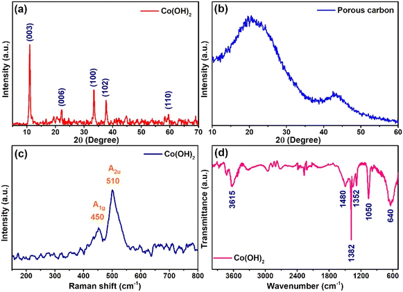 | ||
| Fig. 1 XRD pattern of (a) Co(OH)2 and (b) porous carbon. (c) Raman spectra and (d) FTIR spectra of Co(OH)2. | ||
Raman spectroscopy analysis of the Co(OH)2 is displayed in Fig. 1c. The spectra showed two vibrational bands at 450 and 510 cm−1, corresponding to A1g and A2u, respectively. The observed Raman shift at 450 cm−1 was due to the OCoO vibrational mode.26,27 An intense peak was observed at 510 cm−1, which was assigned to the Co–O–H mode.28 Fourier transform infrared spectroscopy (FTIR) of Co(OH)2 is presented in Fig. 1d. The bands at 3615, 1480, 1382, 1352, 1050, and 640 cm−1 were obtained. A broad peak observed at 3615 cm−1 corresponds to the stretching vibration of the O–H groups.29 A sharp peak appeared at 1382 cm−1, which was the characteristic peak of nitro groups and indicated the presence of intercalated NO3− ions in the cobalt hydroxide.30,31 The peaks appearing at 1480, 1352, and 1050 cm−1 were ascribed to the intercalated carbonate ions in the α-Co(OH)2.30,32 A peak observed at 640 cm−1 was assigned to Co–O–H vibration.31
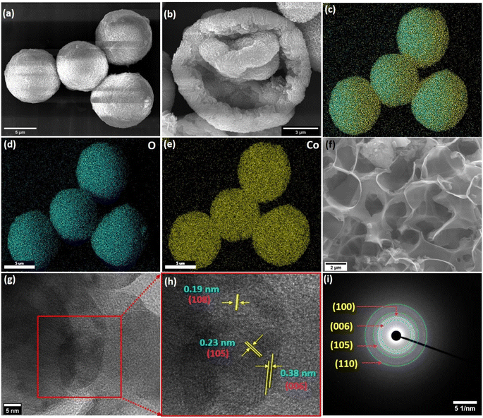
A field emission scanning electron microscopy (FESEM) study showed a hollow sphere-like morphology of the synthesized Co(OH)2 within the diameter of 7–9 μm (Fig. 2a). The magnified image of the Co(OH)2 hollow sphere depicted its hollowness (Fig. 2b), which was formed due to the assemblage of ∼0.22 μm long petals. The elemental color mapping of Co(OH)2 displayed the presence of Co and O, as shown in Fig. 2c–e. The energy dispersive X-ray spectroscopy (EDS) study of the Co(OH)2 is shown in Fig. S1,† in which the Co and O were observed. A highly porous matrix was observed in the FESEM micrograph of the synthesized PC, and it is presented in Fig. 2f. High-resolution transmission electron microscopy (HRTEM) presented in Fig. 2g shows the structural features of Co(OH)2 in more detail. The lattice fringe spacings of 0.38, 0.23, and 0.19 nm attributed to the (006), (105), and (108) planes of Co(OH)2 were observed in the HRTEM micrograph (Fig. 2h) [JCPDS card no.: 46-0605].33,34 The selected area electron diffraction (SAED) pattern of the Co(OH)2 hollow-sphere showed well-ordered diffraction rings corresponding to (006), (100), (105), and (110) planes (Fig. 2i), which coincide with XRD pattern and also confirmed its polycrystalline structure.
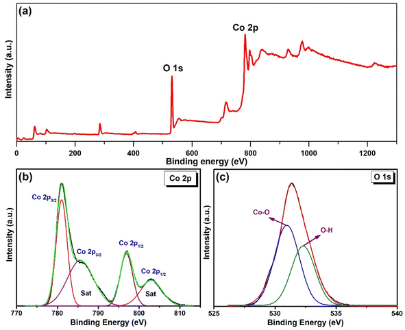
X-ray photoelectron spectroscopy (XPS) analysis of the Co(OH)2 was carried out to assess the chemical states of the elements. The XPS survey spectrum of the Co(OH)2 is shown in Fig. 3a, which indicates the peak appearance of Co 2p and O 1s at binding energies of 531 and 782 eV, respectively. The high-resolution Co 2p spectrum (Fig. 3b) was fitted with two main peaks corresponding to spin–orbit doublets of Co 2p3/2 (781.07 eV), Co 2p1/2 (796.7 eV), and their satellite (sat) peaks (785.6 and 802.9 eV), which confirmed the presence of Co2+ state.35,36 The O 1s spectrum was deconvoluted to two peaks at binding energies of 530.8 and 532.26 eV (Fig. 3c), assigning to metal–oxygen bond and oxygen-containing functional groups, respectively.36
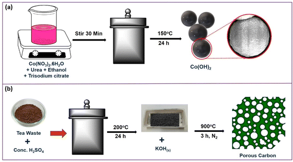
The results from XRD, Raman, FTIR, FESEM, EDS, HRTEM, SAED, and XPS analyses confirmed the formation of Co(OH)2 and PC. Scheme 1 demonstrates the preparation route of the Co(OH)2 and porous carbon. The Co(OH)2 preparation could have plausibly followed the three reaction steps during the hydrothermal process as hydrolysis of urea (eqn (1)), formation of Co(II)-citrate complex (eqn (2)), and nucleation of flowerlike Co(OH)2 via substitution of [Co2(C6H4O7)2]4− complex (eqn (3)).37,38
| NH2CONH2 + 3H2O → 2NH4+ + OH− + HCO3− | (1) |
| Co2+ + citrate → [Co2(C6H4O7)2]4− | (2) |
| [Co2(C6H4O7)2]4− + OH− → Co(OH)2 | (3) |
The detailed formation protocol for the PC is elucidated in our previous work.24 Briefly, during the reaction, the carbon source (i.e. tea waste) first reacts with solid KOH, and intercalation of potassium occurs in the carbon matrix.39 After washing, the removal of potassium leads to the creation of pores. Plausible reaction steps are described as eqn (4)–(8).24
| 2C + 6KOH → 2K2CO3 + 2K + 3H2 | (4) |
| 2K2CO3 → K2O + CO2 | (5) |
| K2CO3 + 2C → 2K + 3CO | (6) |
| CO2 + C → 2CO | (7) |
| C + K2O → 2K + CO | (8) |
3.2 Electrochemical property evaluation
| Co(OH)2 + OH− ↔ CoOOH + H2O + e− | (9) |
| CoOOH + OH− ↔ CoO2 + H2O + e− | (10) |
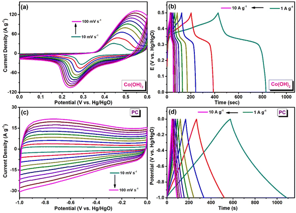 | ||
| Fig. 4 (a) CV curves and (b) GCD curves of Co(OH)2. (c) CV curves and (d) GCD curves of PC in 3 M KOH. | ||
When the scan rate was increased from 10 to 100 mV s−1, the oxidation and reduction peaks shifted towards the forward and backward sides. These findings suggest the diffusion-controlled behavior of the redox reaction. At high scan rates, the electrode material could not efficiently access the electrolyte ions. The Randles–Sevcik plot exhibited a linear connection for the oxidation and reduction peak currents and the square root of the scan rate (Fig. S2†).
The charging and discharging properties of the Co(OH)2 electrode were analyzed through galvanostatic charge–discharge (GCD) measurement (Fig. 4b). These measurements were conducted in a voltage range of 0–0.5 V. A specific capacitance value of 801 F g−1 at a current density of 1 A g−1 was attained for the Co(OH)2 electrode. CV and GCD measurements of PC were performed in the potential window ranging from −1 to 0 V in 3 M KOH. Electrochemical impedance spectroscopy (EIS) of Co(OH)2 was assessed in the frequency range of 0.01–10![[thin space (1/6-em)]](https://www.rsc.org/images/entities/char_2009.gif) 000 Hz. Fig. S3† displays the Nyquist plot of Co(OH)2. EIS measurements were performed to determine the values of charge-transfer resistance (RCT) and internal resistance (RS) of the Co(OH)2 electrode in the aqueous KOH electrolyte during the electrochemical process, and a Nyquist plot was generated (Z′ vs. Z′′) (Fig. S3†). RS and RCT values were determined by fitting the data with an equivalent Randle's circuit (inset of Fig. S3†). In the Nyquist plot, the appearance of a semicircle in the high-frequency region indicates the presence of RCT. RCT originates from the resistance at the electrode–electrolyte interface and can be estimated from the diameter of the semicircle.42,43 RS signifies the combination of the ionic resistance of the electrolyte, the intrinsic resistance of the electrode material, and the contact resistance between the electrode and the current collector.42 RS can be determined from the intercept of the semicircle on the x-axis (Z′) at the high-frequency region. The RS and RCT values of Co(OH)2 were 0.38 and 1.98 Ω, respectively.
000 Hz. Fig. S3† displays the Nyquist plot of Co(OH)2. EIS measurements were performed to determine the values of charge-transfer resistance (RCT) and internal resistance (RS) of the Co(OH)2 electrode in the aqueous KOH electrolyte during the electrochemical process, and a Nyquist plot was generated (Z′ vs. Z′′) (Fig. S3†). RS and RCT values were determined by fitting the data with an equivalent Randle's circuit (inset of Fig. S3†). In the Nyquist plot, the appearance of a semicircle in the high-frequency region indicates the presence of RCT. RCT originates from the resistance at the electrode–electrolyte interface and can be estimated from the diameter of the semicircle.42,43 RS signifies the combination of the ionic resistance of the electrolyte, the intrinsic resistance of the electrode material, and the contact resistance between the electrode and the current collector.42 RS can be determined from the intercept of the semicircle on the x-axis (Z′) at the high-frequency region. The RS and RCT values of Co(OH)2 were 0.38 and 1.98 Ω, respectively.
Fig. 4c and d present the CV and GCD of PC, respectively. The quasi-rectangular cyclic voltammogram and linear galvanostatic charging–discharging curves indicated its electric double-layer capacitive (EDLC) characteristics. PC attained a specific capacitance of 516 F g−1 at a current density of 1 A g−1. This PC was used as the anode material in the assembled asymmetric supercapacitor (ASC) device. The highly porous structure of PC promotes rapid electrolyte ion diffusion and accelerates ion transport within the device, which could contribute to the improved performance of the device.
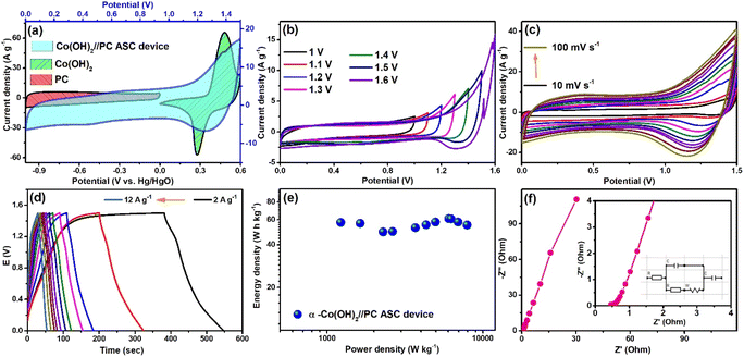
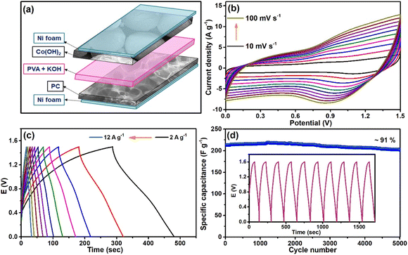
The successful fabrication of the ASC cell encouraged us to construct a solid-state supercapacitor device to demonstrate the potentiality of the synthesized materials in modern portable electronic devices. Here, both the cathode and anode were kept the same as in the previous ASC cell, but the filter paper was replaced by solidified 3 M KOH encapsulated PVA gel. In this case, PVA gel acted as the separator, and aqueous KOH was the electrolyte. This also acts as the electrolyte in the fabricated solid-state supercapacitor device. The as-constructed device is graphically portrayed in Fig. 6a. Then, to analyze the performance of the device, different parameters, such as specific capacitance (CS), energy and power densities, and coulombic efficiency, were evaluated. Fig. 6b presents the CV curves of this device at scan rates varying from 10 to 100 mV s−1, which displays the retention of the initial shape with the increase in scan rates. This depicted the occurrence of reversible electrochemical processes in the device. The GCD curves of the device measured at numerous current densities are shown in Fig. 6c, and the observed CS value at 2 A g−1 was 260 F g−1. The device also exhibited a coulombic efficiency of ∼100% (Fig. S4†) at 6 A g−1; hence, a stability test was conducted at this current density. After ∼5000 cycles of constant charging and discharging processes, the device retained ∼91% of its initial CS value, demonstrating a long lasting shelf life (Fig. 6d). Fig. S5† displays the XRD and FESEM analyses of the Co(OH)2. After ∼5000 GCD cycles, no significant changes were observed in the structural properties and morphology of the electrode material.
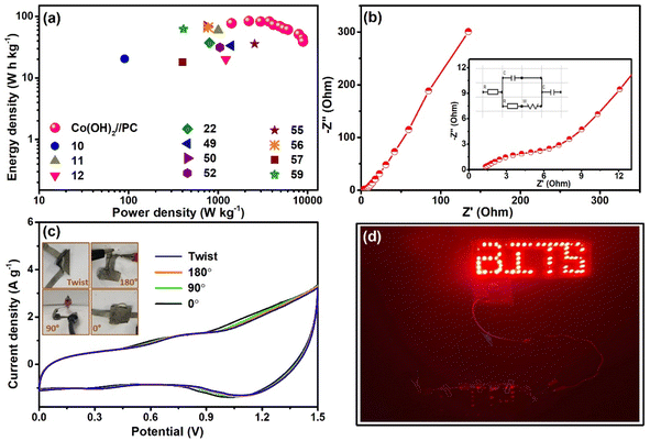
The Ragone plot (Fig. 7a) was derived from the resultant energy and power density values and compared with a few of the values reported on Co(OH)2 and/or porous carbon-based ASC devices. The energy density of the solid-state Co(OH)2//PC device was found to be 76.7 W h kg−1 at a power density of 1416.9 W kg−1. These resultant values were comparable and, in a few cases, superior to the values found in the literature (Table 1). The RS and RCT values of the solid-state ASC were determined from EIS measurements (Nyquist plot and equivalent circuit as inset presented in Fig. 7b). RS and RCT values were 0.95 and 1.41 Ω, respectively. Equivalent circuit resistance (ESR) was calculated by summing RS and RCT values, The low value of ESR of this device contributes to its high power density.8
| Sr. No. | Material | Electrolyte | Potential (V) | Energy density (W h kg−1) | Power density (W kg−1) | Retention (cycles) | Ref. |
|---|---|---|---|---|---|---|---|
| 1 | Co(OH)2/GNS//AC/CFP | 1 M KOH | 1.5 | 19.3 | 187.5 | 109% (20![[thin space (1/6-em)]](https://www.rsc.org/images/entities/char_2009.gif) 000) 000) |
44 |
| 2 | Ni1–Co2–S/Co(OH)2//AC | PVA/KOH | 1.6 | 48.8 | 800 | 88% (10![[thin space (1/6-em)]](https://www.rsc.org/images/entities/char_2009.gif) 000) 000) |
45 |
| 3 | Co(OH)2@PPy//CNTMN | PVA/KOH | 1.6 | 10.53@mW h cm−3 | 0.53@W cm−3 | 89% (5000) | 46 |
| 4 | Co(OH)2 NAs@Ni//CNTs@Ni | 2 M KOH | 1.5 | 19.05 | 112.5 | ∼96% (7000) | 47 |
| 5 | CF–Ni(OH)2//CF–CNT | PVA–KOH | 1.4 | 41.1 | 1400 | 98% (3000) | 48 |
| 6 | CF–Co(OH)xCO3//CF–CNT | PVA–KOH | 1.4 | 33.45 | 1400 | 97.6% (3000) | 49 |
| 7 | MnS/Ni3S2@Co(OH)2//AC | 1 M KOH | 1.5 | 68.6 | 750 | 91.2% (10![[thin space (1/6-em)]](https://www.rsc.org/images/entities/char_2009.gif) 000) 000) |
50 |
| 8 | A-ZCo@NF//AC@GF | 3 M KOH | 1.5 | 365.5@μW h cm−2 | 752.5@μW cm−2 | 80.86% (10![[thin space (1/6-em)]](https://www.rsc.org/images/entities/char_2009.gif) 000) 000) |
14 |
| 9 | Co(OH)2/rGO//AC | PVA/KOH | 1.4 | 28 | 1754 | 89% (4000) | 20 |
| 10 | ACH//ACH | 2 M KOH | — | 6.85 | 601.46 | 95% (5000) | 51 |
| 11 | Co(OH)2//Co(OH)2 | 1 M KOH | 1.2 | 3.96 | 42![[thin space (1/6-em)]](https://www.rsc.org/images/entities/char_2009.gif) 000 000 |
81% (5000) | 21 |
| 12 | AC//Co(OH)2 buds/Ni foam | 6 M KOH | 1.6 | 20.3 | 90.6 | 69.3% (1000) | 10 |
| 13 | β-Co(OH)2//AC | 6 M KOH | 1.6 | 37.3 | 800 | >90% (5000) | 22 |
| 14 | β-Co(OH)2//rGO | 6 M KOH | 1.4 | 20.05 | 1220 | 93% (10![[thin space (1/6-em)]](https://www.rsc.org/images/entities/char_2009.gif) 000) 000) |
12 |
| 15 | Co(OH)2@PANI//AC | 6 M KOH | 1.4 | 31.2 | 1050 | 74.8% (5000) | 52 |
| 16 | Co(OH)2/fCNT//fCNT | PVA![[thin space (1/6-em)]](https://www.rsc.org/images/entities/char_2009.gif) : :![[thin space (1/6-em)]](https://www.rsc.org/images/entities/char_2009.gif) KOH KOH |
1.4 | 3.8 | 7000 | 84% (5000) | 53 |
| 17 | CF/Cu(OH)2/Co(OH)2//CF/AC | PVA–KOH | 1.5 | 3.5@mW h cm−2 | 1.87@mW cm−2 | 81% (12![[thin space (1/6-em)]](https://www.rsc.org/images/entities/char_2009.gif) 000) 000) |
54 |
| 18 | Co2(CO3)(OH)2NDs/NiCo(CO3)(OH)2//graphene | 1 M KOH | — | 35.5 | 2555.6 | 71.3% (10![[thin space (1/6-em)]](https://www.rsc.org/images/entities/char_2009.gif) 000) 000) |
55 |
| 19 | MgCo2O4@α-Co(OH)2/NF-2//AC | PVA–KOH | 1.6 | 65.94 | 773.19 | 91.7% (10![[thin space (1/6-em)]](https://www.rsc.org/images/entities/char_2009.gif) 000) 000) |
56 |
| 20 | AC//AC/MB-400/Co(OH)2 | 3 M KOH | 1.6 | 18 | 400 | 80.05% (5000) | 57 |
| 21 | Cu(OH)2@ZnNi–CoCH//AC | PVA–KOH | 1.5 | 34.75 | 375 | 86.54% (6000) | 35 |
| 22 | Co(OH)2@NiMoS4//AC | 3 M KOH | 2.0 | 59.5 | 1000 | 100% (5000) | 11 |
| 23 | β-Co(OH)2//AC | 6 M KOH | 1.2 | 10 | 300 | 69.6% (5000) | 23 |
| 24 | Co3O4/Co(OH)2//AC | 2 M KOH | 1.5 | 25.6 | 939 | 84.5% (5000) | 58 |
| 25 | Mn–Co(OH)2/CoS//AC | 2 M KOH | 1.65 | 62.1 | 410 | 164.1% (30![[thin space (1/6-em)]](https://www.rsc.org/images/entities/char_2009.gif) 000) 000) |
59 |
| 26 | Co(OH)2//PC | KOH + PVA | 1.5 | 76.7 | 1416.9 | 91% (5000) | This work |
To establish the flexibility of the device, CV measurement was performed when bending it at different angles (Fig. 7c). Almost identical CV profiles were observed for the different bending shapes of this device, which illustrated its remarkable flexibility. The as-fabricated device effectively lit up a panel of red LEDs, which validated its real-life applicability (Fig. 7d).
4. Conclusions
In conclusion, the Co(OH)2 hollow sphere was synthesized using a single-step hydrothermal process. Biomass-derived (i.e., from the tea waste) porous carbon was synthesized using the KOH activation method, which showed a highly porous matrix. Co(OH)2 showed redox activity in an alkaline medium with a high CS value of 801 F g−1 at a current density of 1 A g−1. Moreover, porous carbon exhibited an EDLC nature and CS value of 516 F g−1 at a current density of 1 A g−1. An asymmetric supercapacitor device was assembled using Co(OH)2 as a cathode and PC as an anode. First, the filter paper soaked in KOH was used as an electrolyte/separator to test the ASC device, which verified its good activity as an ASC device. Then, a gel electrolyte with PVA and KOH was prepared to fabricate a flexible solid-state Co(OH)2//PC ASC device. The prepared PVA + KOH gel electrolyte acted as an electrolyte and a separator. The solid-state Co(OH)2//PC ASC device performed well and showed a high CS value of 260 F g−1 at a current density of 2 A g−1. It retained ∼91% of the initial CS value (at 6 A g−1) till ∼5000 cycles. The high-performance Co(OH)2//PC ASC device exhibited an energy density of 76.7 W h kg−1 at a power density of 1416.9 W kg−1. Thus, this study presents an improved performance of cobalt hydroxide and porous carbon for asymmetric supercapacitor devices.Data availability
All relevant data are available from the corresponding authors upon reasonable request.Author contributions
Rajeshvari Samatbhai Karmur and Debika Gogoi: conceptualization, investigation, validation, methodology, formal analysis, data curation, writing – original draft, writing – review & editing, visualization. Manash R. Das: XPS analysis data collection. Narendra Nath Ghosh: resources, funding acquisition, supervision, data curation, writing – review & editing.Conflicts of interest
The authors disclose that they have no conflicting financial interests.Acknowledgements
N. N. G. acknowledges the Cross-Disciplinary Research Framework (CDRF) scheme BITS Pilani, India (Grant: C1/23/121) for providing financial support. The R. S. K. is thankful to CSIR-HRDG, India, for awarding a senior research fellowship (File No. 09/0919(11330)/2021-EMR-I). The authors acknowledge the Central Sophisticated Instrumentation Facility (CSIF), BITS Pilani K. K. Birla Goa Campus, for providing Raman spectroscopy, FESEM, and EDX facilities.References
- A. Buylova, N. Nasiritousi, A. Duit, G. Reischl and P. Lejon, Environ. Sci. Policy, 2024, 159, 103811 CrossRef.
- C. Cruanyes, O. Alcaraz and B. Sureda, Clim. Policy, 2024, 24, 691–705 CrossRef.
- R. Morya, T. Raj, Y. Lee, A. Kumar Pandey, D. Kumar, R. Rani Singhania, S. Singh, J. Prakash Verma and S.-H. Kim, Bioresour. Technol., 2022, 366, 128159 CrossRef CAS PubMed.
- P. Makkar and N. N. Ghosh, ACS Omega, 2020, 5, 10572–10580 CrossRef CAS PubMed.
- S. Natarajan, M. Ulaganathan and V. Aravindan, J. Mater. Chem. A, 2021, 9, 15542–15585 RSC.
- S. Sharma and P. Chand, Results Chem., 2023, 5, 100885 CrossRef CAS.
- S. A. Kadam, K. P. Kadam and N. R. Pradhan, J. Mater. Chem. A, 2024, 12, 17992–18046 RSC.
- Y. Shao, M. F. El-Kady, J. Sun, Y. Li, Q. Zhang, M. Zhu, H. Wang, B. Dunn and R. B. Kaner, Chem. Rev., 2018, 118, 9233–9280 CrossRef CAS PubMed.
- F. Wang, S. Xiao, Y. Hou, C. Hu, L. Liu and Y. Wu, RSC Adv., 2013, 3, 13059–13084 RSC.
- U. M. Patil, S. C. Lee, J. S. Sohn, S. B. Kulkarni, K. V. Gurav, J. H. Kim, J. H. Kim, S. Lee and S. C. Jun, Electrochim. Acta, 2014, 129, 334–342 CrossRef CAS.
- J. Li, J. Zhao, L. Qin, Q. Zhang, X. Tang and Y. Xu, RSC Adv., 2020, 10, 22606–22615 RSC.
- M. Jana, P. Sivakumar, M. Kota, M. G. Jung and H. S. Park, J. Power Sources, 2019, 422, 9–17 CrossRef CAS.
- L. Pan, D. Wang, J. Wang, Y. Chu, X. Li, W. Wang, N. Mitsuzaki, S. Jia and Z. Chen, Phys. Chem. Chem. Phys., 2024, 26, 9096–9111 RSC.
- C. Jagtap, V. Kadam, B. Kamble, P. E. Lokhande, A. Pakdel, D. Kumar, R. Udayabhaskar, A. Vedpathak, N. B. Chaure and H. M. Pathan, J. Energy Storage, 2024, 83, 110666 CrossRef.
- A. S. Pillai, R. Rajagopalan, A. Amruthalakshmi, J. Joseph, A. Ajay, I. Shakir, S. V. Nair and A. Balakrishnan, Colloids Surf., A, 2015, 470, 280–289 CrossRef CAS.
- M. Qorbani, N. Naseri and A. Z. Moshfegh, ACS Appl. Mater. Interfaces, 2015, 7, 11172–11179 CrossRef CAS.
- O. C. Pore, A. V. Fulari, R. V. Shejwal, V. J. Fulari and G. M. Lohar, Chem. Eng. J., 2021, 426, 131544 CrossRef CAS.
- S. Alipoori, S. Mazinani, S. H. Aboutalebi and F. Sharif, J. Energy Storage, 2020, 27, 101072 CrossRef.
- B. Jinisha, K. M. Anilkumar, M. Manoj, C. M. Ashraf, V. S. Pradeep and S. Jayalekshmi, J. Solid State Electrochem., 2019, 23, 3343–3353 CrossRef CAS.
- C. P. Roshni, K. Jithesh, P. M. Anjana, K. G. Raj and R. B. Rakhi, Next Mater., 2024, 4, 100199 CrossRef.
- A. D. Jagadale, V. S. Kumbhar, D. S. Dhawale and C. D. Lokhande, Electrochim. Acta, 2013, 98, 32–38 CrossRef CAS.
- M. Ulaganathan, M. M. Maharjan, Q. Yan, V. Aravindan and S. Madhavi, Chem.–Asian J., 2017, 12, 2127–2133 CrossRef CAS PubMed.
- I. M. Babu, J. J. William and G. Muralidharan, Ionics, 2019, 25, 2437–2444 CrossRef CAS.
- D. Gogoi, R. S. Karmur, M. R. Das and N. N. Ghosh, Energy Fuels, 2023, 37, 14350–14364 CrossRef CAS.
- Z. Wang, S. Ji, F. Liu, H. Wang, X. Wang, Q. Wang, B. G. Pollet and R. Wang, ACS Appl. Mater. Interfaces, 2019, 11, 29791–29798 CrossRef CAS.
- D. McAteer, I. J. Godwin, Z. Ling, A. Harvey, L. He, C. S. Boland, V. Vega-Mayoral, B. Szydłowska, A. A. Rovetta, C. Backes, J. B. Boland, X. Chen, M. E. G. Lyons and J. N. Coleman, Adv. Energy Mater., 2018, 8, 1702965 CrossRef.
- J. Yang, H. Liu, W. N. Martens and R. L. Frost, J. Phys. Chem. C, 2010, 114, 111–119 CrossRef CAS.
- C. Lai, J. Alloys Compd., 2019, 777, 492–498 CrossRef CAS.
- A.-A. Malek Barmi, M. Aghazadeh, B. Arhami, H. M. Shiri, A. A. Fazl and E. Jangju, Chem. Phys. Lett., 2012, 541, 65–69 CrossRef CAS.
- J. P. Cheng, L. Liu, J. Zhang, F. Liu and X. B. Zhang, J. Electroanal. Chem., 2014, 722–723, 23–31 CrossRef CAS.
- L. Liu, J. P. Cheng, J. Zhang, F. Liu and X. B. Zhang, J. Alloys Compd., 2014, 615, 868–874 CrossRef CAS.
- J. T. Mehrabad, M. Aghazadeh, M. G. Maragheh, M. R. Ganjali and P. Norouzi, Mater. Lett., 2016, 184, 223–226 CrossRef CAS.
- J. Li, Z. Li, F. Zhan and M. Shao, Chem. Sci., 2021, 12, 1756–1761 RSC.
- Y. Kou, J. Liu, Y. Li, S. Qu, C. Ma, Z. Song, X. Han, Y. Deng, W. Hu and C. Zhong, ACS Appl. Mater. Interfaces, 2018, 10, 796–805 CrossRef CAS PubMed.
- Y. Liu, X. Cao, L. Cui, Y. Zhong, R. Zheng, D. Wei, C. Barrow, J. M. Razal, W. Yang and J. Liu, J. Power Sources, 2019, 437, 226897 CrossRef CAS.
- Y. Xu, Z. Liu, D. Chen, Y. Song and R. Wang, Prog. Nat. Sci.: Mater. Int., 2017, 27, 197–202 CrossRef CAS.
- D. Gogoi, R. S. Karmur, M. R. Das and N. N. Ghosh, Sustainable Energy Fuels, 2022, 6, 3599–3610 RSC.
- Z. Huang, Y. Zhao, Y. Song, Y. Zhao and J. Zhao, Colloids Surf., A, 2017, 516, 106–114 CrossRef CAS.
- J. Wang and S. Kaskel, J. Mater. Chem., 2012, 22, 23710–23725 RSC.
- L. Cao, F. Xu, Y. Y. Liang and H. L. Li, Adv. Mater., 2004, 16, 1853–1857 CrossRef CAS.
- J. Jiang, J. Liu, R. Ding, J. Zhu, Y. Li, A. Hu, X. Li and X. Huang, ACS Appl. Mater. Interfaces, 2011, 3, 99–103 CrossRef CAS PubMed.
- J. Huang, Y. Xie, Y. You, J. Yuan, Q. Xu, H. Xie and Y. Chen, Adv. Funct. Mater., 2023, 33, 2213095 CrossRef CAS.
- N. O. Laschuk, E. B. Easton and O. V. Zenkina, RSC Adv., 2021, 11, 27925–27936 RSC.
- C. Zhao, F. Ren, X. Xue, W. Zheng, X. Wang and L. Chang, J. Electroanal. Chem., 2016, 782, 98–102 CrossRef CAS.
- T. Xu, G. Li and L. Zhao, Chem. Eng. J., 2018, 336, 602–611 CrossRef CAS.
- J. S. Lee, D. H. Shin, W. Kim and J. Jang, J. Mater. Chem. A, 2016, 4, 6603–6609 RSC.
- T. Peng, H. Wang, H. Yi, Y. Jing, P. Sun and X. Wang, Electrochim. Acta, 2015, 176, 77–85 CrossRef CAS.
- D. Ghosh, M. Mandal and C. K. Das, Langmuir, 2015, 31, 7835–7843 CrossRef CAS.
- J. Yu, Z. Hou, H. Zhang and X. Zhou, Fuel, 2024, 357, 129754 CrossRef CAS.
- X. Hu, Y. Xiao, X. Liu, C. Wang, P. Xu, T. Tan, H. Yue, Y. Xing and X. Liu, Int. J. Hydrogen Energ, 2024, 60, 107–117 CrossRef CAS.
- S. Yang, K. Cheng, K. Ye, Y. Li, J. Qu, J. Yin, G. Wang and D. Cao, J. Electroanal. Chem., 2015, 741, 93–99 CrossRef CAS.
- A. Keshavarz, J. Tashkhourian and S. F. Nami-Ana, J. Energy Storage, 2023, 73, 108825 CrossRef.
- R. Ranjithkumar, S. E. Arasi, P. Devendran, N. Nallamuthu, A. Arivarasan, P. Lakshmanan, S. Sudhahar and M. K. Kumar, Diamond Relat. Mater., 2020, 110, 108120 CrossRef CAS.
- B. K. Satpathy, S. Patnaik and D. Pradhan, ACS Appl. Energy Mater., 2022, 5, 77–87 CrossRef CAS.
- D. Lee, Q. X. Xia, J. M. Yun and K. H. Kim, Appl. Surf. Sci., 2018, 433, 16–26 CrossRef CAS.
- Z. Liu, Y. Qiu, A. Zhang, W. Yang, C. J. Barrow, J. M. Razal, A. Li and J. Liu, Appl. Surf. Sci., 2021, 568, 150856 CrossRef CAS.
- C. Xu, Y. Chen, Y. Ma, J. Huang, J. Zhao and H. Xu, Electrochim. Acta, 2021, 367, 137475 CrossRef CAS.
- J. Mei, W. Fu, Z. Zhang, X. Jiang, H. Bu, C. Jiang, E. Xie and W. Han, Energy, 2017, 139, 1153–1158 CrossRef CAS.
- Z. Gan, X. Ren, Y. Sun, M. Sun, Y. Yan, B. Cao, W. Shen, H. Yu, Z. Li and Y. Fu, J. Energy Storage, 2023, 69, 107934 CrossRef.
Footnotes |
| † Electronic supplementary information (ESI) available. See DOI: https://doi.org/10.1039/d4ra05106h |
| ‡ Rajeshvari Samatbhai Karmur and Debika Gogoi contributed equally to this paper. |
| This journal is © The Royal Society of Chemistry 2024 |

