 Open Access Article
Multi-phosphine-chelated iron-carbide clusters via redox-promoted ligand exchange on an inert hexa-iron-carbide carbonyl cluster, [Fe6(μ6-C)(μ2-CO)4(CO)12]2−†
Caitlyn R.
Cobb
 ,
Ren K.
Ngo
 ,
Emily J.
Dick
 ,
Vincent M.
Lynch
and
Michael J.
Rose
 *
*
Department of Chemistry, The University of Texas at Austin, Austin, TX 78712, USA. E-mail: mrose@cm.utexas.edu
First published on 24th June 2024
Abstract
We report the reactivity, structures and spectroscopic characterization of reactions of phosphine-based ligands (mono-, di- and tri-dentate) with iron-carbide carbonyl clusters. Historically, the archetype of this cluster class, namely [Fe6(μ6-C)(μ2-CO)4(CO)12]2−, can be prepared on a gram-scale but is resistant to simple ligand substitution reactions. This limitation has precluded the relevance of iron-carbide clusters relating to organometallics, catalysis and the nitrogenase active site cluster. Herein, we aimed to derive a simple and reliable method to accomplish CO → L (where L = phosphine or other general ligands) substitution reactions without harsh reagents or multi-step synthetic strategies. Ultimately, our goal was ligand-based chelation of an Fen(μn-C) core to achieve more synthetic control over multi-iron-carbide motifs relevant to the nitrogenase active site. We report that the key intermediate is the PSEPT-non-conforming cluster [Fe6(μ6-C)(CO)16] (2: 84 electrons), which can be generated in situ by the outer-sphere oxidation of [Fe6(μ6-C)(CO)16]2− (1: closo, 86 electrons) with 2 equiv. of [Fc]PF6. The reaction of 2 with excess PPh3 generates a singly substituted neutral cluster [Fe5(μ5-C)(CO)14PPh3] (4), similar to the reported reactivity of the substitutionally active cluster [Fe5(μ5-C)(CO)15] with monodentate phosphines (Cooke & Mays, 1990). In contrast, the reaction of 2 with flexible, bidentate phosphines (DPPE and DPPP) generates a wide range of unisolable products. However, the rigid bidentate phosphine bis(diphenylphosphino)benzene (bdpb) disproportionates the cluster into non-ligated Fe3-carbide anions paired with a bdpb-supported Fe(II) cation, which co-crystallize in [Fe3(μ3-CH)(μ3-CO)(CO)9]2[Fe(MeCN)2(bdpb)2] (6). A successful reaction of 2 with the tripodal ligand Triphos generates the first multi-iron-chelated, authentic carbide cluster of the formula [Fe4(μ4-C)(κ3-Triphos)(CO)10] (9). DFT analysis of the key (oxidized) intermediate 2 suggests that its (μ6-C)Fe6 framework remains fully intact but is distorted into an axially compressed, ‘ruffled’ octahedron distinct from the parent closo cluster 1. Oxidation of the cluster in non-coordinating solvent allows for the isolation and crystallization of the CO-saturated, intact closo-analogue [Fe6(μ6-C)(CO)17] (3), indicating that the intact (μ6-C)Fe6 motif is retained during initial oxidation with [Fc]PF6. Overall, we demonstrate that redox modulation beneficially ‘bends’ Wade-Mingo's rules via the generation of electron-starved (non-PSEPT) intermediates, which are the key intermediates in promoting facile CO → L substitution reactions in iron-carbide-carbonyl clusters.
Introduction
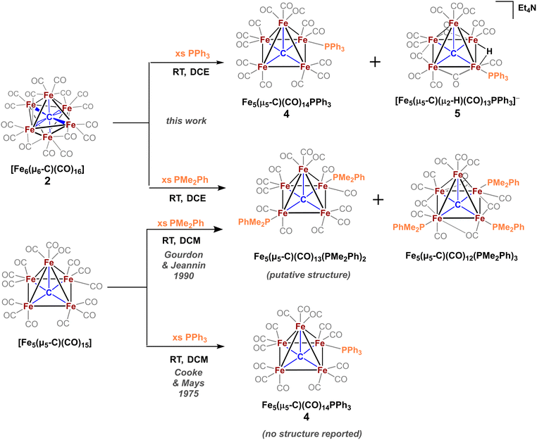
The family of iron carbonyl carbide clusters well studied by Wampler et al.,1 Churchill et al. 1971,2 Churchill et al. 1974,3 Beno et al.,4 Tachikawa et al.,5 and others was of substantial interest to organometallic chemists as models for Fischer–Tropsch chemistry and as a scaffold with highly fluxional ligands.1–5 More recently, Berben et al. have investigated carbide and the closely related nitride clusters as small molecule catalysts for transformations like CO2 reduction.6–9 Since 2011, such carbide clusters have garnered attention from bioinorganic chemists as spectroscopic (and—aspirationally—structural or functional) models of the nitrogenase active site cluster (FeMoco) due to the authentic inorganic carbide that resides at the interstitial site.10 However, attempts to transform these clusters into relevant FeMoco models via direct ligand substitution have met with limited success11–13 and the presence of ubiquitous CO ligands (and corresponding low, diamagnetic spin states) precludes their relevance to nitrogenase.Historically, many of these clusters have proven a difficult platform upon which to achieve substitution of the CO ligands for anions—including biologically relevant sulfides, thiolates and alkoxides.11,14 Some success has been reported, such as reactions of the six-iron cluster [Fe6(μ6-C)(μ2-CO)(CO)12]2− with strongly π accepting ligands such as NO+ and SO2 (and R–N![[triple bond, length as m-dash]](https://www.rsc.org/images/entities/char_e002.gif) C with nitride clusters).15–17 Historically, the five-iron neutral cluster Fe5(μ5-C)(CO)15 was the first iron-carbide cluster (neé, metal-carbide cluster) to be isolated in 1962,1 and its four-iron congener Fe4(μ4-C)(CO)13 was isolated several decades later (1981).18 However, it has been decades since the ligand substitution reactions of neutral carbide clusters have been thoroughly explored. Notably, Cooke and Mays (1975) reported the reactivity of Fe5(μ5-C)(CO)15 with phosphines and showed that stronger σ donors (PMe2Ph) resulted in a greater extent of substitution (1, 2 or 3 substitutions) than weaker σ donors (PPh3, single substitution). To date, only one complex has been structurally characterized (Gourdon & Jeannin, 1990), namely [Fe5(μ5-C)(CO)11(PMe2Ph)3].19,20 Incidentally, the same report detailed the synthesis of a five-iron cluster ligated by bidentate phosphine bis(dimethylphosphine)ethane; however its X-ray structure was not disclosed.
C with nitride clusters).15–17 Historically, the five-iron neutral cluster Fe5(μ5-C)(CO)15 was the first iron-carbide cluster (neé, metal-carbide cluster) to be isolated in 1962,1 and its four-iron congener Fe4(μ4-C)(CO)13 was isolated several decades later (1981).18 However, it has been decades since the ligand substitution reactions of neutral carbide clusters have been thoroughly explored. Notably, Cooke and Mays (1975) reported the reactivity of Fe5(μ5-C)(CO)15 with phosphines and showed that stronger σ donors (PMe2Ph) resulted in a greater extent of substitution (1, 2 or 3 substitutions) than weaker σ donors (PPh3, single substitution). To date, only one complex has been structurally characterized (Gourdon & Jeannin, 1990), namely [Fe5(μ5-C)(CO)11(PMe2Ph)3].19,20 Incidentally, the same report detailed the synthesis of a five-iron cluster ligated by bidentate phosphine bis(dimethylphosphine)ethane; however its X-ray structure was not disclosed.
Analogous substitution using Fe4(μ4-C)(CO)13 with PR3 variants by Bradley resulted in preliminary structural data of thrice-substituted [Fe4(μ4-C)(μ3-CO)(CO)9(PMe3)3], and a putative tetra-substituted variant was spectroscopically characterized by 1H/13C/31P NMR.21 Relatedly, a singly substituted phosphine variant was explored by Wadepohl, who reported the X-ray structure of the protonated four-iron cluster [Fe4(μ4-CH)(CO)12(PPh3)H]−;22 this was an expansion on Muetterties' extensive body of work with the four-iron cluster series.4,5,23
The eventual aim of our research program is to systematically understand how to controllably insert a variety of multidentate ligands onto iron-carbide-carbonyl clusters pertaining to nitrogenase FeMoco. Indeed, the use of multidentate ligands to stabilize otherwise unisolable iron-sulfide clusters was a key milestone in Holm's foundational biomimetic work with Fe3S4-type clusters.24–26 Recent successes achieved by Suess and coworkers include the isolation of previously unisolable FeS clusters with extended multidentate ligand scaffolds; this includes their isolation of an elusive alkyl-[Fe4S4]3+ cluster stabilized by a scorpionate ligand.27 A report by Agapie et al. employing a multidentate bis(diisopropylamino)cyclopropenylidene (BAC) ligand to give a carbyne FeS cluster is also notable.28,29 This approach has yet to be applied to iron clusters that contain the authentic inorganic carbide, in large part due to the challenges in controlling CO substitution (and prevention of cluster disproportionation) as discussed above. Instead, some of the most biologically relevant models to date have approached FeMoco models with a ‘carbide-like’ motif bound to iron centers.30,31 We sought in this work to elucidate the design principles and ligand-binding preferences of iron-carbide-carbonyl clusters with commercially available, multidentate phosphine ligands as a stepping stone towards more biomimetic chemistry. We hypothesized that such phosphine ligands would accelerate our understanding of intra-cluster (preferred) vs. inter-cluster (not preferred) binding, apical vs. equatorial ligation, and ‘single-site chelation’ vs. ‘multi-site chelation’ preferences. We deemed phosphine substitution onto substitutionally active, neutral clusters like Fe5(μ5-C)(CO)15 as the preferred route to design stable chelation modes.
The primary synthetic obstacle to performing such reactions is the need to isolate the neutral Fe5(μ5-C)(CO)15 cluster,32 whose low yield in our hand (5–15%) from gram-scale quantities of [Fe6(μ6-C)(CO)16]2− severely limited the scope and depth of explorative chemistry. In related work, Zacchini et al. reported the redox-enabled addition of Lewis acids, utilizing the two-electron reduction of [Fe6(μ6-C)(CO)16]2− to [Fe6(μ6-C)(CO)15]4− (structurally characterized), which then stably binds Au(PPh3)+ and H+ without cluster disproportionation.33 Notably, both anionic precursors conform to the polyhedral skeletal electron pair theory (PSEPT) electron counting regime, wherein both clusters possess 84 e− in accordance with the 14n + 2 rule for closo structures. Thus, the synthetic addition of Lewis acid ‘ligands’ like H+ or Au(PPh3)+ does not violate PSEPT.
In contrast to the addition of Lewis acids enabled by reduction, we wished to pursue the addition of Lewis bases enabled by oxidation. As such, we envisioned that the two-electron oxidation of [Fe6(μ6-C)(CO)16]2− to the non-PSEPT intermediate [Fe6(μ6-C)(CO)16] (82 e−; 2 e− short of PSEPT rules) would facilitate the addition of 2 e− ligand(s) such as phosphine. This strategy builds on our previous work, wherein we reported that the addition of two CO ligands to [Fe6(μ6-C)(CO)16] (82 e−) afforded the isolable nido species Fe6(μ6-C)(CO)18 (88 e−, 14n + 4).32 In this work, we utilize the in situ oxidation of [Fe6(μ6-C)(CO)16]2− to promote binding of phosphine-based ligands without proceeding through the low-yielding Fe5(μ5-C)(CO)15 or Fe4(μ4-C)(CO)13 clusters. We demonstrate the benefits of this synthetic route and report the structures and spectroscopic properties of novel (authentic) carbide clusters supported by multidentate phosphines that drive towards the lower CO/Fe ratios, which are ultimately necessary for biological relevance to nitrogenase active sites.
Results and discussion
Redox activation for ligand substitution and isolation of closo-Fe6(μ6-C)(CO)17 (3)
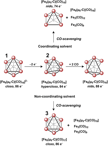
In 1971, Churchill predicted the isolability of a neutral 86 e− cluster of the formula closo-Fe6(μ6-C)(CO)17.2,3 In a 2017 report, we isolated the closely related, neutral 88 e− species nido-Fe6(μ6-C)(CO)18, whose formulation was justified on the basis of (i) strong Raman features indicative of highly symmetric breathing modes (corroborated by DFT calculations); (ii) the lack of bridging CO features in the IR spectrum; (iii) a Mössbauer spectrum indicating the presence of ‘three pairs’ of equivalent iron centers.32 Thus, the possibility of the long-predicted 86 e− species closo-Fe6(μ6-C)(CO)17—incidentally, whose Ru-based congener is structurally characterized34—was excluded by the above evidence. Synthetically, 88 e−nido-Fe6C(CO)18 was isolated via outer-sphere oxidation of the 86 e− cluster of the formula closo-[Fe6C(CO)16]2− (1) in tetrahydrofuran (THF) under a CO atmosphere.32 DFT calculations accurately predicted the nido configuration of Fe6(μ6-C)(CO)18 in the form of an open-faced, pentagonal neutral cluster—consistent with the PSEPT 14n + 4 rule for nido clusters. In the absence of a CO atmosphere, the oxidation of 1 in THF ultimately results in cluster decay, as the cluster scavenges carbonyls from itself, disproportionating to a mixture of neutral products including Fe6(μ6-C)(CO)18, Fe5(μ5-C)(CO)15 and Fe3(CO)12, upon both 1 and 2 e− oxidation.32,35 We thus hypothesized that an in situ, outer-sphere oxidation of cluster 1 would generate a meta-stable, non-PSEPT cluster—putatively the 84 e− cluster [Fe6(μ6-C)(CO)16] (2) (vide infra for computational details). Due to its under-coordination (i.e. low PSEPT e− count), we posited that this cluster would have a high affinity for the addition of exogenous ligands (Schemes 1–3).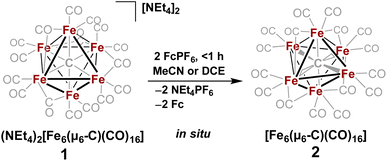 | ||
| Scheme 2 In situ oxidation of 1 to form the non-PSEPT intermediate 2, the key precursor to all of the ligand additions in this report. | ||
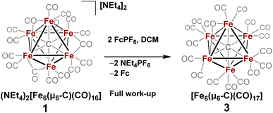 | ||
| Scheme 3 In situ oxidation of 1 in non-coordinating solvent to form 3, the stable six-iron closo cluster. | ||
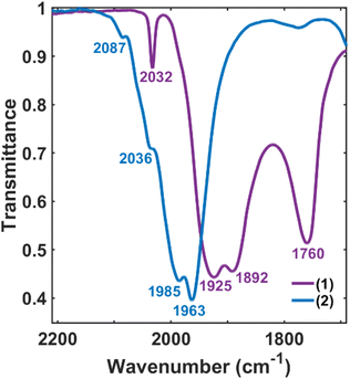
The validity of the above approach was tested by the reaction of a deep violet MeCN solution of 1 with 2.1 equiv. of [Fc]PF6 to generate cluster 2. The IR spectrum was monitored, and over the course of 30 min the terminal CO features [1892(s), 1925(s) and 2032(w) cm−1] and the bridging CO feature [1760(m) cm−1] were diminished in intensity. The reddened solution exhibited a blue-shifted set of terminal CO features at 1963(s), 1985(s), 2036(w) and 2087(w) cm−1—indicative of cluster oxidation (Fig. 1). The IR spectrum was persistent for several hours, but at extended times (12–24 h, in the dark) the CO features broadened, indicative of cluster disproportionation and/or decay.
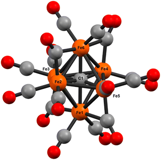
However, when this reaction was conducted in non-coordinating DCM, significant differences were observed. Upon addition of 2.5 equiv. of [Fc]PF6 to a violet DCM solution of 1 the solution turned black. After 10 minutes, the solvent was removed in vacuo and washed with pentane, diethyl ether (Et2O), and toluene to remove ferrocene and Fe5(μ5-C)(CO)15. Extraction into fluorobenzene (FPh) resulted in a deep black solution, which upon cooling afforded diffraction-quality black prisms of the long predicted closo-Fe6(μ6-C)(CO)17 (3). We drew from this unexpected result the following conclusions: first, the initial oxidized intermediate 2 is an intact, six-iron species; second, the closo neutral species 3 is unstable in coordinating solvents such as THF and MeCN and likely decomposes into Fe6(μ6-C)(CO)18, Fe5(μ5-C)(CO)15 and Fe3(CO)12, leading to its reddish color; third, as observed in the 2017 report, excess CO(g) is required as the ligand to prevent the disproportionation of product six-iron clusters due to the instability of 2. On this basis, we selected a <1 h timeframe for in situ ligand addition and moving forward the solvent choice in each reaction.
Reaction of 2 with monodentate phosphines: dimethylphenylphosphine (PMe2Ph) and PPh3
The only phosphine-substituted, iron-carbide-carbonyl cluster reported in the CSD is that of Gourdon & Jeannin, namely Fe5(μ5-C)(CO)12(PMe2Ph)3, which was prepared in a straightforward fashion from Fe5(μ5-C)(CO)15 and PMe2Ph.‡20 On this basis, PMe2Ph was selected to validate the proposed synthetic approach. The addition of ∼9 equiv. of PMe2Ph to in situ-generated 2 in DCE red-shifted the most intense ν(CO) feature from 1990 → 1950 cm−1, consistent with PMe2Ph binding.20 Further spectroscopic evidence for PMe2Ph binding was observed following column chromatography: The triply substituted cluster [Fe5(μ5-C)(CO)12(PMe2Ph)3] was identified by its characteristic IR features (2045, 1928, and 1857 cm−1) and 31P NMR resonances (CDCl3: δ 18.4, 22.1 ppm).20 However, this species proved unisolable due to the presence of other putative species such as doubly substituted Fe5(μ5-C)(CO)13(PMe2Ph)2 and singly substituted Fe5(μ5-C)(CO)14(PMe2Ph). Nonetheless, these IR data overall provided strong evidence that the in situ-oxidized species 2 (six-iron cluster) provided an analogous pattern of ligand substitution to the five-iron cluster Fe5(μ5-C)(CO)15.To minimize the number of substitution products, we reasoned that a weaker phosphine ligand like PPh3 would provide a more tractable cluster—despite the lack of crystallographic precedent.19 According to Cooke & Mays, the reaction of 9 equiv. of PPh3 with in situ-generated 2—followed by differential extraction (Et2O vs. FPh) and air-free chromatography—provided two modified clusters: black plates of Fe5(μ5-C)(CO)14(PPh3) (4, reported but not crystallized by Cooke & Mays), and red-violet plates of the novel hydride species NEt4[Fe5(μ5-C)(μ2-H)(μ2-CO)3(CO)9(PPh3)] (5, Scheme 4). Notably, the hydride cluster 5 was not identified in the spectroscopic analyses performed by Cooke & Mays (IR, 31P NMR, and EA).19
Additional observations shed light on the stoichiometry and variance in product profiles between our work using the six-iron cluster 2, versus Cooke & Mays using the five-iron cluster Fe5(μ5-C)(CO)15. The initial extraction of the PPh3 reaction mixture with pentane ultimately provided (in addition to copious amounts of ferrocene) chiffon-coloured blocks of the non-carbide complex Fe(CO)4(PPh3). The isolation of such a mononuclear iron species provides insight into the stoichiometric decapping reaction that must occur in the conversion of six-iron clusters to five-iron clusters. That is, the loss of one iron in the transformation of 2 to 4 is accounted for by the formation of Fe(CO)4(PPh3). However, the origin of the anionic hydride species 5 was not explained. We speculate that the zero-valent iron present in Fe(CO)4(PPh3) could act as a reductant—thus forming [Fen(CO)x(PPh3)y](PF6)n, where n = 1, 2—in the formation of the anionic hydride species 5.36
Reaction of 2 with bidentate phosphines: dppe, dppp and bdpb
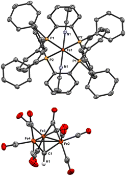
To explore phosphine substitution more controllably, bidentate phosphines were utilized to leverage the chelate effect. The reactions of in situ-generated 2 in DCE with two equiv. of dppe or dppp provided a multitude of carbonyl-containing products (over 15)—most of which were unisolable (despite varying solvent extractions and chromatography), and some of which were isolable but not amenable to crystallization.We next selected a rigid bisphosphine, namely 1,2-bis(diphenylphosphino)benzene (bdpb). Intriguingly, the reaction of two equiv. of bdpb with 2 in MeCN afforded no isolable, phosphine-bound clusters. Instead, red plates of the ‘compound’ iron species [Fe3(μ3-CH)(CO)10]2[FeII(MeCN)2(bdpb)2] (6, Scheme 5) were isolated from Et2O. The observation of this low nuclearity three-iron μ3-CH species indicates a greater extent of cluster deconstruction via iron ‘clipping’ by the chelating ligands. This is in contrast to the intact iron-carbide-phosphine clusters obtained using the monodentate phosphines (PPh3 and PMe2Ph).
 | ||
| Scheme 5 Reaction of 1,2-bis(diphenylphosphino)benzene (bdpb) with 2, [Fe3(μ3-CH)(CO)10]2[FeII(MeCN)2(bdpb)2] co-crystallized as 6. | ||
Ultimately, we attribute the lack of success in the bidentate approach to two factors. First, the inherent flexibility of the ethyl or propyl linkers, which contributes to the intractability of the product profile and difficulty in crystallizing products. Second, there are two sub-factors that preclude the desired ‘edge’ chelation on an intact cluster: (i) the limited span of the ethyl or propyl linkers in dppe and dppp and (ii) the constrained geometry of bdpb, which absolutely enforces single-site chelation. Indeed, the isolation of compound 6 illustrates that enforced, single-site chelation leads merely to lower nuclearity, unsubstituted clusters (alongside mono-iron products).
Some comparative insight is gained by inspection of the analogous ruthenium-carbide literature: Webster et al. elegantly demonstrated that the carbon chain length in a bis(diphenylphosphine) series (1–4 CH2 units: dppm, dppe, dppp, and dppb, respectively) were crystallographically or spectroscopically demonstrated to determine the chelation mode on Ru5 clusters. For example, dppm and dppe only exhibit binding at a single Ru site; in contrast, dppp binds at two adjacent Ru vertices. Furthermore, the longest carbon chain in dppb facilitates binding of the Ru5 cluster at opposite vertices.37 Such isolable Ru clusters exhibit greater kinetic stability than the corresponding Fe clusters and thus may provide ‘snapshots’ of the unisolable Fe clusters that might enable the reactions presented herein.
Reaction of 2 with tridentate phosphines
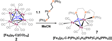
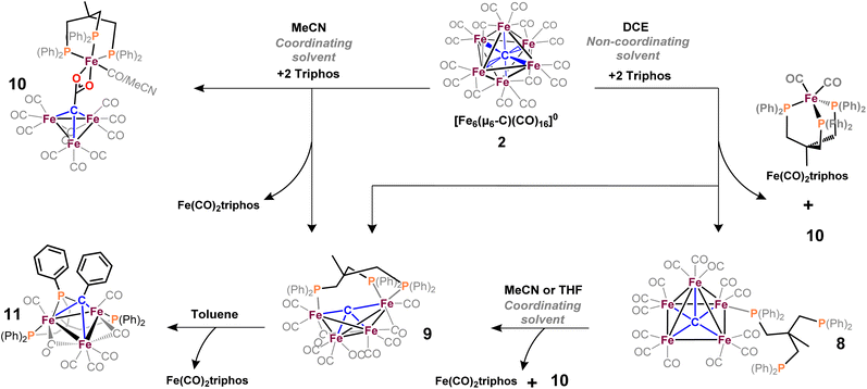
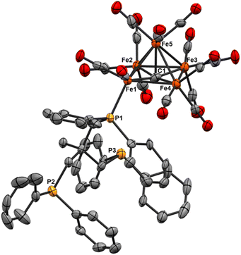
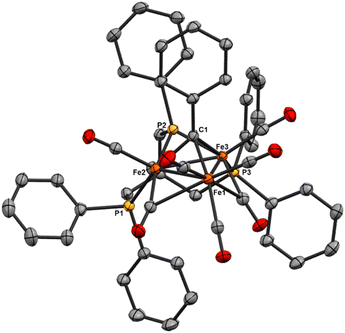
We reasoned that alkyl-linked bis-phosphines (vide supra) had a similar propensity to extract single, chelated iron sites from carbide-based clusters (per bdpb, cluster 6). On this basis, we first selected the linear tridentate phosphine ligand bis(2-diphenylphosphinoethyl)phenylphosphine (Scheme 6). However, the reaction of 1.1 equiv. of (Ph2PCH2CH2)2PPh with 2 led to only one isolable product. Extraction with toluene followed by chromatography and pentane vapor diffusion afforded the three-iron cluster 7, which exhibits a pseudo-(μ3-C)Fe3 core supported by 8 CO ligands and the multi-dentate phosphine ligand (Scheme 6). Notably, 7 exhibits one desirable property and one undesirable property: The desirable property is successful bidentate chelation of a single iron site, which remains bound to the ‘carbide’ core. The undesirable property is that the third phosphine is covalently bonded to the central carbon; notably, the R3P–C(μ3)Fen motif is reminiscent of the heterometallic cluster [(μ3-CPMe3)(Fe(CO)3)2Co(CO)3]− reported by Shriver.38 Ultimately, the formation of the P–C bond diverged from our goal of retaining the authentic inorganic carbide.We thus speculated that the third phosphine could not extend all the way to the adjacent iron site. As such, we considered the longer propyl-linked congener (Ph2PCH2CH2CH2)2PPh, but this ligand is not commercially available. An intriguing alternative was the commercially available (tripodal) ligand Triphos, which utilizes 3-carbon linkers between each phosphine in a tripod rather than a linear format. The reaction of 2 with two equiv. Triphos in DCE provided fewer products than the ‘linear’ triphosphine, and most of these products proved crystallographically tractable. Indeed, several Triphos-ligated iron clusters were ultimately isolated from this reaction: pentane extraction provided ferrocene, unreacted Triphos, and two distinct black iron-carbonyl products. The first product exhibited strongly blue-shifted νCO features [2077 (m), 2022(s), and 2006 cm−1 (s)] and no bridging CO features. The crystallization of this species afforded grey-green needles of Fe5(μ5-C)(CO)14(κ1-Triphos) (8), wherein one Triphos ‘arm’ displaces a single CO on an otherwise unperturbed five-iron framework (Scheme 7, Fig. 5).
The second product was minimally soluble in pentane, but it was ultimately isolated in greater quantities via Et2O extraction. Column purification provided green-black crystals of the desired, κ3-Triphos cluster Fe4(μ4-C)(μ2-CO)(CO)8(κ3-Triphos) (9). This cluster represents the first multi-iron chelated iron-carbide cluster, and its structural metrics and implications are discussed further below (vide infra, X-ray section). The subsequent red band (THF eluent; vapor diffusion of hexane into toluene) provided deep red prisms identified as the ‘clipped’ cluster Fe3(CO)(CO2)Fe(CO)(κ3-Triphos) (10). This cluster exhibits a distal {(κ3-Triphos)Fe(CO)}2+ moiety linked to the Fe3 core by a {μ3-CCO2}4− bridge. The formation of both 10 and 9 (four-iron clusters) from 8 (five-iron cluster) as the common precursor was confirmed by dissolution of 8 in MeCN (Scheme 7), which then provided clusters 9 and 10 as the primary products.
Notably, both the ‘clipped’ 10 and ‘intact’ 9 comprise four irons; we thus postulated 9 as the precursor to 10. However, the dissolution of 9 in toluene followed by crystallization provided evidence against this hypothesis: Crystallographic analysis of the resulting black crystals revealed a phenyl transfer reaction from a PPh2 moiety to the carbide, thus forming a (μ3-CPh)Fe3 core in 11. In parallel, re-crystallization attempts of 9 in Et2O lead to isolation of the (known) mononuclear species (Triphos)Fe(CO)2, whose formation stoichiometrically accounts for the loss of one iron site in the conversions 2 → 8, 8 → 9 and 9 → 11.
We suspected cluster 8 (with the κ1-Triphos motif) to be a precursor to the more highly substituted clusters 9 and 10. To explore this hypothesis, the addition of MeCN to a light hazel solution of 8 in Et2O induced an immediate color change to amber. After 3 min, the IR spectrum no longer exhibited the νCO features of 8 (2079 cm−1), and a very broad and red-shifted feature near 1980 cm−1 was observed (Fig. S36†). Ultimately chromatographic, IR and X-ray analyses revealed the presence of 9 and 10. This unambiguously demonstrates the solvent-induced (MeCN) cluster conversion of 8 → 9 + 10. The same result was obtained in THF (albeit over hours, not seconds), suggesting the accelerative role of coordinating solvent to facilitate complete Triphos coordination (i.e. CO displacement) onto these clusters.
X-ray structures
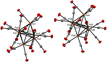 | ||
| Fig. 2 ORTEP diagram (50% thermal ellipsoids) for Fe6(μ6-C)(CO)17 (3), shown as a grown structure of an asymmetric unit cell with two half-clusters (see ESI, Fig. S37†). | ||
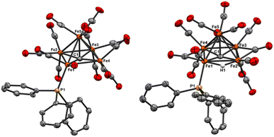
In the basal Fe4 plane, the (PPh3)Fe1–Fe2 and (PPh3)Fe1–Fe4 bond distances are 2.7362(15) and 2.6998(15) Å, respectively. These distances are longer than the athwart Fe3–Fe2 and Fe3–Fe4 distances [2.6341(16) and 2.6326(16) Å]. We attribute the longer Fe1-based distances to a more electropositive Fe1 site (versus Fe3). We posit that this is a result of the stronger PPh3 σ donation to Fe1, and the compensatory electron density at the Fe3(CO)3 moiety, which has greater Fe(dπ)|CO(π*) back-bonding. The basal plane iron carbide exhibits only a slight elongation of the Fe3–C1 bond [the iron site diagonal to phosphine binding: Fe1–C1 1.888(8) Å and Fe3–C1 1.932(8) Å] (Table 1). The carbide C–Fe5(apical) bond [1.949(8) Å] is nearly identical to that found in the unsubstituted parent cluster Fe5(μ5-C)(CO)15, namely 1.948(7) Å. However, the displacement of the carbide from the basal plane (see the visualization in Fig. S47†) in 4 [d = 0.145 Å] is greater than the displacement found in the parent cluster [d = 0.09 Å]. This is consistent with the previously observed trend of increased carbide displacement with increased cluster electron density.20,39 For example, both the dianion [Fe5(μ5-C)μ2-(CO)2(CO)12]2− and the triply substituted cluster Fe5(μ5-C)(CO)12(PMe2Ph)3 exhibit greater carbide displacements [0.18 and 0.20(1) Å, respectively] than the parent neutral cluster.20,32
| Bond | 4 | 5 | 8 | Fe5C(CO15) | Fe5C(CO12)(PhMe2P)3 | [Fe5C(CO14)]2− | |
|---|---|---|---|---|---|---|---|
| Fe-(μ5-C) | Fe1–C1 | 1.888(8) | 1.859(3) | 1.897(10) | 1.875(8) | 1.858 | 1.882(13) |
| Fe2–C1 | 1.874(8) | 1.852(3) | 1.867(10) | 1.897(7) | 1.876 | 1.866(14) | |
| Fe3–C1 | 1.932(8) | 1.879(3) | 1.932(10) | 1.865(8) | 1.868 | 1.853(13) | |
| Fe4–C1 | 1.899(8) | 1.857(3) | 1.876(10) | 1.893(7) | 1.868 | 1.862(14) | |
| Fe5–C1 | 1.949(7) | 2.015(3) | 1.978(10) | 1.948(7) | 2.022 | 1.993(13) | |
| Fe–Fe | Fe1–Fe2 | 2.7998(15) | 2.7018(6) | 2.728(2) | 2.6331(15) | 2.656 | 2.657(3) |
| Fe1–Fe4 | 2.7362(15) | 2.6450(6) | 2.681(2) | 2.6496(15) | 2.642 | 2.506(3) | |
| Fe1–Fe5 | 2.6285(15) | 2.5923(6) | 2.5937(19) | 2.557(16) | 2.579 | 2.637(3) | |
| Fe2–Fe3 | 2.6341(16) | 2.5757(6) | 2.628(2) | 2.6703(15) | 2.622 | 2.651(3) | |
| Fe2–Fe5 | 2.6045(16) | 2.6400(6) | 2.623(2) | 2.5869(15) | 2.651 | 2.579(3) | |
| Fe3–Fe4 | 2.6326(16) | 2.5552(6) | 2.624(2) | 2.6780(15) | 2.585 | 2.692(3) | |
| Fe3–Fe5 | 2.6248(16) | 2.5949(6) | 2.590(2) | 2.6466(16) | 2.643 | 2.594(3) | |
| Fe4–Fe5 | 2.6014(16) | 2.5937(6) | 2.619(2) | 2.5997(14) | 2.544 | 2.607(3) | |
| Fe–P | Fe1–P1 | 2.2880(18) | 2.2245(8) | 2.261(3) | — | 2.263 | — |
| Fe2–P2 | — | — | — | — | 2.324 | — | |
| Fe3–P3 | — | — | — | — | 2.248 | — | |
| (μ5-C)-planeFe4 | C1–Fe4 | 0.145 | 0.183 | 0.18 | 0.09 | 0.20(1) | 0.18 |
| Fe–H | Fe1–H1 | — | 1.82(5) | — | — | — | — |
| Fe4–H1 | — | 1.83(5) | — | — | — | — |
The PPh3-substituted iron site in 5 is—as in 4—an equatorial iron, and the PPh3 is similarly located below the basal plane.7,20 The Fe1–P1 bond in 5 [2.2245(8) Å] is slightly shorter than that in neutral 4 [2.2880(18) Å]. The shorter bond in 5 is attributed to the anionic charge and the corresponding increase in iron oxidation states, namely an average of +0.8 in 4versus +1.0 in 5. Relatedly, the nitride cluster [Fe5(μ5-N)(CO)13(PPh3)]− reported by Berben et al.—also PSEPT 74 e− like 4 and 5—exhibits an intermediate Fe–P bond length [2.2472(15) Å].7 This is attributable to the combined effects of the nitride cluster's same 1− charge (like cluster 5), yet a lower iron oxidation state (+0.8 as with 4). Overall, the adjacency of the hydride to the PPh3–Fe1 unit is rationalized according to the stabilization of the hydride by the most electropositive iron site.
Regarding the carbide, the C1–Fe5(apical) bond length in 5 [2.015(3) Å] is elongated as compared with 4 [1.949(7) Å]. This correlates with the greater carbide displacement (d) from the basal plane in 5 (d = 0.183 Å) compared with that in 4 (d = 0.147 Å). In an unexpected fashion, the combined effect (overall charge and phosphine ligation) in 5 on carbide displacement is less than that observed in the neutral, tri-substituted Fe5(μ5-C)(CO)12(PMe2Ph)3, which exhibits a larger displacement (d = 0.20 Å). Indeed, the binding of PPh3 and hydride in mono-anionic 5 results in a similar carbide displacement as found in the di-anionic cluster [Fe5(μ5-C)μ2-(CO)2(CO)12]2− (0.18 Å).20,32 Furthermore, the importance of ligand identity over cluster charge is underscored in the case of the cluster Fe5(μ5-C)μ2-SO2(CO)13, whose π acidic SO2 ligand leads to a much smaller carbide displacement of d = 0.10.15
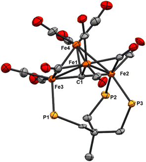 | ||
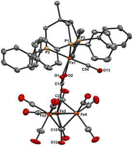
| Fig. 6 ORTEP diagram (50% thermal ellipsoids) for the tri-substituted Fe4 cluster Fe4(μ4-C)(μ2-CO)2(CO)8(κ3-Triphos) (9); H atoms and phenyl rings are omitted for the sake of clarity. | ||
The location of the phosphine donors on the ‘wing-tip’ iron sites (Fe2 and Fe3) is consistent with most literature studies (Fe-nitride clusters). However, the wing-tip motif is slightly different from the triply PMe3 ligated Fe-carbide cluster reported by Bradley,21 which exhibits only one wing-tip PMe3 and two PMe3 in the basal locations. The orientation of the phosphine donors above the axial Fe2–C1–Fe3 motif is also consistent with the reported Fe4 structures (Table 2).21,22,42,43
![[thin space (1/6-em)]](https://www.rsc.org/images/entities/char_2009.gif) 23
23
| Bond or angle | 8 | Fe4C(CO)13 | Fe4C(Co)10(PMe3)3 | [Fe4(CH)(CO)12(PPh3)H]1− | [Fe4C(CO)12]2− | |
|---|---|---|---|---|---|---|
| Fe-(μ4-C) | Fe3–C1 | 1.813(7) | 1.797(4) | 1.838(4) | 1.908(7) | 1.810(7) |
| Fe1–C1 | 1.962(7) | 1.999(4) | 1.979(4) | 1.926(9) | 1.969(5) | |
| Fe4–C1 | 1.943(7) | 1.988(4) | 2.104(4) | 1.973(8) | 1.969(5) | |
| Fe2–C1 | 1.801(7) | 1.800(4) | 1.758(4) | 1.973(8) | 1.786(7) | |
| Fe–Fe | Fe3–Fe1 | 2.6332(15) | 2.624(1) | 2.644(19) | 2.669(2) | 2.637(1) |
| Fe3–Fe4 | 2.6326(16) | 2.637(1) | 2.644(19) | 2.613(2) | 2.637(1) | |
| Fe1–Fe2 | 2.6016(15) | 2.647(1) | 2.644(19) | 2.630(2) | 2.653(1) | |
| Fe4–Fe2 | 2.7028(16) | 2.640(1) | 2.644(19) | 2.624(2) | 2.653(1) | |
| Fe1–Fe4 | 2.5287(15) | 2.545(1) | 2.528(1) | 2.584(2) | 2.534(1) | |
| Fe–P | Fe3–P1 | 2.247(2) | — | Not reported | 2.238(2) | — |
| Fe2–P2 | 2.269(2) | — | Not reported | — | — | |
| Fe2–P3 | 2.2545(19) | — | Not reported | — | — | |
| Wing torsion | Dihedral | 102.17 | 101 | 102.4 | 107.55 | 101 |
| Fe2–Ccarbide–Fe3 | Fe2–C1–Fe3 | 175.3(4) | 175 | 174 | 172.4(5) | 178 |
Finally, we speculate that the coordination of three phosphine ligands onto the two wing-tip irons in 9 thermodynamically destabilizes the cluster core, an effect primarily compensated for by multi-iron chelation. The ‘cluster chelation’ prevents (immediate) cluster disproportionation, but may not completely compensate for the unsymmetrical Fe electronics as evidenced by the eventual formation of the phenyl-transfer product [Fe3(μ3-CPh){Triphos(PPh2)2(PPh)}(CO)7] (11) and mononuclear (Triphos)Fe(CO)2.
The Fe3(CO)8(μ3-CO)(μ3-aceto-κ2-O) cluster unit in 10 (Fig. 7) is unique in the CCDC, although several similar structures have been reported with generalized μ3-CR moieties, such as Fe3(CO)8(μ3-CCH3)(μ3-COCH3) reported by Hursthouse in 1983.49 The cluster NEt4[Fe3(CO)8(μ3-CO)(μ3-CCH3)] was reported by Zacchini more recently, and also features the same μ3-CO found in 10.40 The Fe–Fe bond distances in 10 are similar to those found in the Hursthouse cluster (Fe–Feavg 2.2559 Å vs. 2.520 Å, respectively). Ultimately, the similarity of the cluster core bond metrics of 10 with reported clusters suggests that the tri-iron subunit of the ‘clipped’ structure 10 is mostly unaffected (electronically) by the linked monometallic site.
The coordination geometry of the detached ferrous site is best compared with the Fe(II) complexes of trisphosphinephenylborate (aka BP3R) complexes reported by Peters, namely monomeric [(BP3R)Fe(acetato-κ2O)] and dimeric μ2-oxalato-(κ2O)2-[(BP3Cy)Fe(CO)]2.50,51 In contrast to these structures, the sixth coordination site in 10 is occupied by CO and MeCN (1![[thin space (1/6-em)]](https://www.rsc.org/images/entities/char_2009.gif) :
:![[thin space (1/6-em)]](https://www.rsc.org/images/entities/char_2009.gif) 1, crystallographically). The Fe–P, Fe–C(aceto) and Fe–CO bond lengths are all similar. Ultimately, this structural result demonstrates that Triphos can (thematically) ‘clip’ a single iron site from the progenitor Fe4 cluster framework.
1, crystallographically). The Fe–P, Fe–C(aceto) and Fe–CO bond lengths are all similar. Ultimately, this structural result demonstrates that Triphos can (thematically) ‘clip’ a single iron site from the progenitor Fe4 cluster framework.
Spectroscopic characterization (NMR and IR)
Fe6(μ6-C)(μ2-CO)(CO)17. The ν(CO) features in the IR of 3 are essentially equivalent to those of the nido-five iron compound Fe5(μ5-C)(CO)15 with a leading feature at 2095, and dominant peaks at 2018, 1994, 1973, and 1941. The notable difference is a medium-intensity feature at 1821 cm−1 correlated with the single bridging carbonyl in the crystal structure. 13C-NMR shows multiple resonances in the carbonyl region at 212.24, 21.11, and 209.45 ppm.
Fe5(μ5-C)(CO)14(PPh3) (4). The IR spectrum of 4 exhibits a red-shift in its leading ν(CO) feature (2078 cm−1) compared with the analogous feature at 2097 cm−1 in the unsubstituted analog Fe5(μ5-C)(CO)15. This is consistent with the substitution of a strong π-acceptor (CO) for a σ donating but relatively electron-poor phosphine and is in accordance with the report from Cooke and Mays.19 Additionally, the increased number of ν(CO) features in 4 relative to the unsubstituted cluster indicates a decrease in the symmetry of the nido cluster 4 upon phosphine substitution for CO (see Table S1†). This is further supported by the increased relative intensity of the leading feature at 2078 cm−1. We posit that the medium intensity, sharp leading feature at 2078 cm−1 is Raman active and IR forbidden in symmetric, unsubstituted clusters such as Fe5(μ5-C)(CO)15, which shows only a very weak but sharp feature, possibly thermally allowed, at 2098 cm−1. This stretch is symmetry allowed by the newly imposed asymmetry of phosphine binding, and we observed a similar effect in the case of 5 and 8 with their analogous features at 2041 and 2078 cm−1, respectively. The 31P NMR spectrum exhibits a resonance at 53.73 ppm that is consistent with a metal-bound phosphine, as well as a resonance corresponding to unbound phosphine. We posit that this indicates only dynamic ligation in the solution state. The participation of phosphine ligands in intramolecular ligand exchange on iron carbonyl clusters has been reported by Wadepohl previously.22 Interestingly, the 13C NMR spectrum of Fe5(μ5-C)(CO)14(PPh3) in C6D6 exhibits a carbide resonance at 490.11 ppm, slightly deshielded relative to the reported 486.0 ppm resonance for the neutral, unsubstituted cluster Fe5(μ5-C)(CO)15.32
NEt4[Fe5(μ5-C)(μ2-H)(CO)13PPh3] (5). The IR spectrum of 5 exhibits both terminal v(CO) peaks and multiple bridging v(CO) peaks, consistent with the CO binding modes and overall symmetry observed in the crystal structure (Table S1†). The 31P NMR spectrum exhibits a single resonance at 62.17 ppm, consistent with a metal-bound phosphine, thus indicating that the structure in solution is consistent with the crystal structure. The resonance shift is deshielded relative to the neutral analog 4, which is consistent with the expectation for an anionic cluster. The proposed assignment of a bound hydride in the X-ray structure is fully supported by the 1H NMR spectrum, which exhibits a hydride resonance at −11.71 and −11.75 ppm (doublet, J = 24 Hz). For comparison, the six-iron, tri-anionic hydride cluster [Fe6(μ6-C)(μ2-H)(CO)15]3− reported by Zacchini et al. features a hydride resonance at −20.7 ppm; this suggests that the more downfield resonance for our monoanionic, lower nuclearity cluster is reasonable given the comparatively weaker shielding effect expected in the less strongly charged five-iron cluster.52 NOESY analysis reveals coupling between the −11.71 and −11.75 ppm resonance and aryl peaks from PPh3, supporting the structural assignment of the hydride location bridging between Fe1 and Fe4, adjacent to the PPh3 binding site on Fe1. The 13C NMR of NEt4[Fe5(μ5-C)(μ2-H)(CO)13PPh3] in d3-MeCN exhibits a carbide resonance at 488.63 ppm. This is unexpected, as it is more similar to the neutral, PPh3 substituted cluster (490.11 ppm) than to other charged clusters. We speculate that ligand and hydride substitution induces chemical and symmetry changes to the cluster that have a greater influence on the carbide 13C resonance than the overall cluster electronics, which contradicts the previously reported literature explanation.
Fe5(μ5-C)(CO)14(Triphos) (8). As in the other mono-substituted five-iron cluster 4, the 31P NMR spectrum of 8 exhibits a labile Triphos ligand, even in a non-coordinating solvent such as deuterated benzene.
The spectrum features six dominant resonances, one of which integrates ∼50:1–3 with the other five. We expected two or three, one indicating bound phosphine, and the others the free Triphos arms. We speculate that these additional, persistent (by repeated column purification) resonances are attributable to variable binding modes of the three Triphos arms occurring transiently in solution (see Fig. S25.†) The spectrum is dominated by a resonance at −25.64 ppm, which corresponds to free Triphos, likely a combination of some excess Triphos contamination and complete ligand dissociation in solution.
The carbide resonance at 489.33 ppm is deshielded in a similar fashion relative to Fe5(μ5-C)(CO)15—to a similar extent to cluster 4. Also similar to cluster 4, cluster 8 possesses only terminal carbonyls, with the leading IR feature at 2078 cm−1, a similar red-shift relative to the spectrum of Fe5(μ5-C)(CO)15 as that of 4 at 2079 cm−1. This indicates that despite the lability–and likely the variable binding motifs–of the phosphine in solution, it has a notable impact on the electronics and is analogous to PPh3 binding. The asymmetry induced by mono-phosphine binding of the sterically encumbered Triphos ligand on a single equatorial iron vertex is also observable in the v(CO) features. In this case, a moderately intense and sharp feature appears at 2078 cm−1, with broad, prominent features at 2011 and 1995 cm−1. As with 4, we attribute the presence of this peak to the breaking of pure Oh symmetry in the cluster.
Fe4(μ4-C)(μ2-CO)2(CO)8(κ3-Triphos) (9). The 13C NMR carbide resonance of 9 is distinct from that of the neutral tetra-iron carbide cluster, Fe4(μ4-C)(CO)13, at 485.34 ppm (versus 468.9 ppm in the unsubstituted cluster).21,52 The downfield shift indicates a significantly different carbide environment after Triphos ligation. Interestingly, the shift downfield with Triphos ligations as compared to the neutral, unsubstituted cluster is more extreme (Δδ = 16.44 ppm) than that reported for the tetra-substituted Fe4C(CO)9(PMe3)4 (Δδ = 2.6 ppm), despite the lower extent of CO substitution and the comparative electron deficiency of Triphos donors relative to PMe3. This is a greater downshift than that induced by 2 e− cluster reduction (Δδ = 9.1 ppm) (Table 3). It is unclear if non-bonding interactions between the exposed carbide and the 3 Å distal Triphos scaffold induce further deshielding. Indeed, the reduction and protonation of the Fe4 cluster to generate monoanionic [Fe4C(CO12)H]− result in the opposite effect, with an upfield shift of 4.7 ppm (Table 4).
| Dihedral δ (°) | Fe–C–Fe (°) | μ4-C 13C NMR (ppm) | |
|---|---|---|---|
| a From Bradley et al.21 b Kaupp et al.52 | |||
| Fe4C Triphos | 102.17 | 175.31 | 485.34 |
| Fe4C(CO)13 | 101a | 175a | 468.9b |
| Fe4c(CO)10(PMe3)3 | 102.4a | 174a | Not reported |
| Fe4C(CO)9(PMe3)4 | Not reported | Not reported | 471.5a |
| [Fe4(C)(CO12)H]− | 104a | 174a | 464.2a |
| [Fe4C(CO12)]2− | 101a | 178a | 478.0a |
Unlike Fe5(μ5-C)(κ1-Triphos)(CO)14 (8), the 31P NMR spectrum exhibits two dominant resonances: a broad singlet at 49.70 ppm and a sharp singlet at −24.67 ppm; these two resonances integrate 1![[thin space (1/6-em)]](https://www.rsc.org/images/entities/char_2009.gif) :
:![[thin space (1/6-em)]](https://www.rsc.org/images/entities/char_2009.gif) 2. We posit that this reflects two phosphine arms being consistently unbound in solution, generating an undercoordinated and thus reactive cluster species. This is consistent with the observed formation of 11 from 9 over time in solution via a reaction between the carbide and a phosphine arm. It is conceivable that the observed reactivity (vide supra), whereby the carbide is reactive in the parent cluster Fe4(μ4-C)(CO)13 but not in 9, is explained by Triphos coordination over the butterfly carbide face sterically protecting the otherwise reactive carbide in non-coordinating solvent.
2. We posit that this reflects two phosphine arms being consistently unbound in solution, generating an undercoordinated and thus reactive cluster species. This is consistent with the observed formation of 11 from 9 over time in solution via a reaction between the carbide and a phosphine arm. It is conceivable that the observed reactivity (vide supra), whereby the carbide is reactive in the parent cluster Fe4(μ4-C)(CO)13 but not in 9, is explained by Triphos coordination over the butterfly carbide face sterically protecting the otherwise reactive carbide in non-coordinating solvent.
The IR spectrum of 9 exhibits eight sharp features in the ν(CO) ‘neutral carbonyl cluster’ region (2050–1900 cm−1 for terminal CO and ∼1800 cm−1 for bridging), at 2059, 2042, 2035, 1971, 1944, 1918, (terminal) and 1884 and 1799 cm−1 (bridging). Such features closely parallel the CO binding motifs observed in the crystal structure. Multiple sharper features—rather than the commonly broad ν(CO) peaks in more symmetric clusters—are likely a result of the decreased symmetry upon Triphos binding.
Computational investigation of the non-PSEPT intermediate (2)
Density functional methods used in the literature on iron carbonyl carbide clusters have varied, depending on the application. Debeer & Holland and coworkers modeled the charged and neutral versions of six-iron-carbide, nitride, and oxide carbonyl clusters. They used the BP86 functional and a combination of basis set families, a dense integration grid, and the dielectric continuum model (COSMO) to model electronic structures and XES and XAS spectra. Zacchini and coworkers modeled the electronic structures and relative Gibbs free energy values of di- and tetra-anionic iron carbide carbonyl clusters and their proposed intermediates using the range-separated functional ωB97-x, Ahlrich's basis set family, and a C-PCM implicit solvent model.52 Our group previously performed geometry optimization on neutral six-iron clusters using the hybrid B3PW91 functional and Pople basis sets.32 In another report from DeBeer and coworkers in collaboration with our group, anionic iron and iron-molybdenum carbonyl clusters were modeled using B3LYP, Ahlrichs and CP(PPP) basis sets for the calculation of their Mössbauer parameters.53 An important distinction between previous examples and the challenge reported herein of structurally predicting 2 is that most literature precedent is premised upon a structurally characterized cluster. Due to a lack of crystal structures, our computational approach thus required rigorous validation. However, to our knowledge, no rigorous validation or benchmarking studies on iron-carbide-carbonyl clusters have been reported. Therefore, we endeavored to select and validate a computational toolkit suitable to approach this family of clusters. These methods are detailed in the ESI,† and the key conclusions are discussed below.
Accuracy in the modeling of transition metal compounds is dependent on the extent of Hartree–Fock (HF) contribution and the type of metal-ligand system.54 We selected functionals from available literature: B3LYP,53 BP86,55 ωB97-x52 and B3PW91;32 these functionals utilize an increasing percent of HF contribution (0–20%, Table S14†). For this purpose, we also tested 15% HF contribution versions of two hybrid functionals, B3LYP-15. Separately, we selected the minimally augmented versions from the Ahlrichs basis set family in light of their widespread use for transition metals, as well as iron-carbide carbonyl specifically (see details in the ESI†).52,53,55
We selected the optimal functional and basis set for geometry optimization of 2 by determining the accuracy of several functionals using the closely related (also neutral) and structurally characterized neutral cluster Fe5(μ5-C)(CO)15 (Tables S11 and S12†). Multiple combinations of functional and basis sets provided reasonable results in terms of structural RMSD and selected bond lengths between [Fe5(μ5-C)(CO)15]X-ray and [Fe5(μ5-C)(CO)15]DFT (Tables S16 and S17†) and vibrational analysis (Tables S18–S21 and Fig. S50–60†). Among them, the BP86-D4/TZVP combination provided a converged gas-phase geometry of 2 with only small (less than 100 cm−1) imaginary frequencies (Fig. 9).
The evaluated imaginary frequencies emanated from ‘breathing modes’ involving all cluster atoms. To eliminate these frequencies, small, randomized distortions of the starting coordinates followed by re-optimization were attempted, including increasing the optimization threshold and increasing the angular integration grid number. None of the established methods for resolving imaginary frequencies proved successful, so the parameters were re-evaluated. The literature precedent shows that charged clusters in this family can be modeled using the implicit solvation model C-PCM.52,56,57 We thus returned to the validation compound Fe5(μ5-C)(CO)15 and evaluated the effect of C-PCM with a dielectric constant of 9.08 corresponding to dichloroethane. The optimized geometry with C-PCM was nearly identical to the same calculation performed without C-PCM; however, four carbonyls shifted from terminal motifs to structurally inaccurate bridging motifs (Fig. S61.†) The simulated vibrational spectrum reflects this and thus contradicts the experimental data (Table S23†). We further applied C-PCM with a range of dielectric constants aiming to eliminate the imaginary frequencies, but these calculations all provided essentially equivalent geometries and vibrational spectra (Tables S24 and S25†). Ultimately, the discrepancy between the experimental and simulated CO vibrational modes when C-PCM was applied to [Fe5(μ5-C)(CO)15]DFT indicated that optimization in the gas-phase would be most suitable for modeling 2 (vide infra). More generally, we concluded that the addition of C-PCM is inconsistent when used for modeling neutral iron-carbide carbonyl clusters. In contrast, preliminary computations using the anionic cluster 1 suggest that C-PCM is not only suitable but also necessary for convergence. [Note: such results on the anionic cluster(s) are outside the scope of this report.] Ultimately, the close agreement in bond metrics and vibrational spectra between [Fe5(μ5-C)(CO)15]X-ray and the gas-phase model [Fe5(μ5-C)(CO)15]DFT (Tables S16 and S17†) inspired confidence in the simulated geometry of 2DFT presented herein.
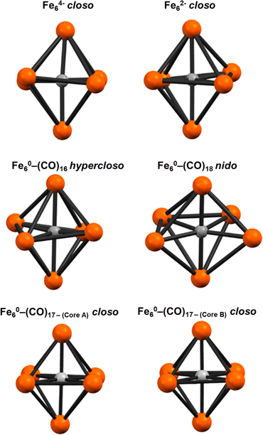
The formulation of the PSEPT electron counting for 2 is consistent with a hypercloso model in an analogous extension of PSEPT for metal clusters [closo: 86 e− (14n + 2) → hypercloso: 84 e− (14n)]. Similarly, some theoretical models of borohydride clusters60—and limited examples of crystallographically characterized 6-borane and alane clusters61,62—can be formulated as ‘hypercloso’.59,63,64 The geometric variation in the Fe6(μ6-C) core of 2DFT (compared with known 6-vertex closo and nido iron carbide clusters, including 3) was analyzed via continuous shape analysis using the program SHAPES, which determines the ideality of a structure with respect to ideal polyhedra.65 The Fe6(μ6-C) core of 2DFT was analyzed alongside the crystallographic coordinates of closo [Fe6(μ6-C)(CO)16]2− and closo [Fe6(μ6-C)(CO)15]4−,33 as well as 3 and the (previously)32 DFT-calculated model for nido Fe6(μ6-C)(CO)18 (Fig. 10, Table 6). As expected, both anionic closo structures correlated strongly with an octahedron and produced the lowest deviation of the four structures (0.23 for each). Interestingly, the neutral closo cluster cores produced lower deviations, at 0.087 and 0.099. The nido cluster also resulted in a low deviation from octahedral (3.37), but with diminished fidelity compared to the closo examples; the nido cluster also exhibited a lower deviation from trigonal prism and pentagonal clusters (19.66 and 9.71, respectively). In contrast, 2DFT exhibits a lower deviation from octahedral clusters (0.60), as well as a lower deviation from trigonal prism and pentagonal pyramid clusters (14.11 and 26.77, respectively) compared with either the closo or the nido structures.
The axial Fe–C(carbide) bonds (Fe1–C1 and Fe6–C1 = 1.880 Å) in 2DFT are slightly shorter than the equatorial Fe–C1 bonds (1.894 Å). This trend is similar to the iron-carbide bonds experimentally determined for [Fe6(μ6-C)(CO)16]2− (Table 5). The axial Fe1–C1–Fe6 angle in 2DFT is exactly linear at 180°, but the corresponding equatorial angles Fe2–C1–Fe3 and Fe4–C1–Fe5 are distorted by equal magnitudes in opposite directions (+169.14° and −169.14° respectively), resulting in a ‘ruffled’ equatorial motif. In contrast, the crystal data for the closo core of [Fe6(μ6-C)(CO)16]2− show only small deviations from the ideal 180° for all three angles, with no clear pattern. However, the lengths of the Fe–Fe bonds in 2DFT deviate minimally from the Fe–Fe bond lengths in the crystallographically defined closo core of [Fe6(μ6-C)(CO)16]2− (Table 5).32
| Fe6(μ6-C)(CO)16 (2DFT) | (PPh4)2[Fe6(μ6-C)(CO)16]a | Fe6(μ6-C)(CO)18a (DFT) | |
|---|---|---|---|
| a Ref. 32. | |||
| PSEPT geometry | Hypercloso | Closo | Nido |
| axial Fe1–C1 | 1.880 | 1.878(5) | 2.0759 |
| axial Fe6–C1 | 1.880 | 1.874(5) | 2.0554 |
| Fe2–C1 | 1.894 | 1.886(5) | 1.9812 |
| Fe3–C1 | 1.894 | 1.898(5) | 1.9526 |
| Fe4–C1 | 1.894 | 1.897(4) | 1.8168 |
| Fe5–C1 | 1.894 | 1.881(4) | 1.8615 |
| Fe1–C1–Fe6 | 180 | 174.51 | — |
| Fe2–C1–Fe4 | 169.14 | 173.05 | — |
| Fe3–C1–Fe5 | 169.14 | 177.62 | — |
| Fe1–Fe2 | 2.539 | 2.6561(9) | 2.4508 |
| Fe1–Fe3 | 2.792 | 2.5964(9) | 2.5963 |
| Fe1–Fe4 | 2.539 | 2.6771(9) | 2.9032 |
| Fe1–Fe5 | 2.792 | 2.7559(9) | 3.5890 |
| Fe2–Fe3 | 2.690 | 2.5795(8) | 2.8228 |
| Fe3–Fe4 | 2.690 | 2.8186(8) | 2.5851 |
| Fe4–Fe5 | 2.690 | 2.6663(8) | 2.6042 |
| Fe5–Fe2 | 2.690 | 2.6050(8) | 2.6730 |
| Fe6C structure | PSEPT class | C 5v | O h | D 3h |
|---|---|---|---|---|
| Fe6(μ6-C)(CO)18 | nido | 19.661 | 3.372 | 9.713 |
| [Fe6(μ6-C)(CO)16]2− | closo | 27.461 | 0.231 | 14.308 |
| [Fe6(μ6-C)(CO)16]4− | closo | 27.030 | 0.234 | 14.119 |
| [Fe6(μ6-C)(CO)16] (2GP–DFT) | hypercloso | 26.770 | 0.600 | 14.111 |
| [Fe6(μ6-C)(CO)17] core A | closo | 28.978 | 0.087 | 15.653 |
| [Fe6(μ6-C)(CO)16] core B | closo | 28.879 | 0.099 | 15.857 |
The four μ2-carbonyls in 2DFT are semi-bridging (as in the dianionic cluster) with asymmetric Fe–C bond lengths of 1.858 and 2.130 Å. Overall, the distortions from any PSEPT geometry (particular from closo) are reasonable for an electron deficient cluster in that no bonds are broken or drastically elongated. There is a slight (and expected) shortening of the metal–metal bonds and the metal–carbide bonds, with small changes in Fe–C–Fe bond angles to accommodate the strain. Meanwhile, the carbonyl bonding indicates no significant change compared with the 86 e−closo structure. Due to decreased electron density on the cluster (neutral versus 2−), a slight decrease in Fe–CO π back-bonding leading to slightly longer Fe–CO and shorter C–O bonds was anticipated; however, this was not observed. We speculate that the change in Fe–CO bonding is limited due to the more significant distortions around the iron-carbide core. This phenomenon appears to compensate for the electron deficiency of the cluster.
Overall, the calculated structure of 2DFT exhibits limited distortions from the closo symmetry of the experimental structure of the corresponding dianion, albeit with slightly shortened iron-carbide bonds and a ‘ruffling’ of the equatorial iron-carbide bonds; the semi-bridging and terminal CO ligands remain relatively undisturbed. This suggests that the metastable, intermediate, non-PSEPT (14n) 2 accommodates the loss of two electrons from closo (14n + 2) primarily within the iron-carbide framework and Fe(CO) motifs with minimal overall changes.
![[triple bond, length as m-dash]](https://www.rsc.org/images/entities/char_e002.gif) O) region at ∼1990 cm−1. The lack of resolution in the v(C
O) region at ∼1990 cm−1. The lack of resolution in the v(C![[triple bond, length as m-dash]](https://www.rsc.org/images/entities/char_e002.gif) O) region is attributed to the solution-drop-cast nature of the samples of reaction mixtures (see Table S1†, spectroscopic results section), rather than an isolated crystalline sample. Ultimately, the computational vibrational analysis for 2DFT provides a reasonable IR spectrum that is consistent with both its simulated structure and the experimental data.
O) region is attributed to the solution-drop-cast nature of the samples of reaction mixtures (see Table S1†, spectroscopic results section), rather than an isolated crystalline sample. Ultimately, the computational vibrational analysis for 2DFT provides a reasonable IR spectrum that is consistent with both its simulated structure and the experimental data.
Conclusions
We reach the following conclusions:(1) The historical obstacle of performing ligand substitutions on the stable, canonical cluster [Fe6]2− can be circumvented by redox-mediated ligand substitution. In particular, the in situ two-electron oxidation of [Fe6]2− to [Fe6]0 provides an under-coordinated cluster that participates in simple ligand substitution reactions with phosphines. Evidence for the intact intermediate [Fe6]0 is supported spectroscopically and by the structurally characterized six-iron closo neutral cluster Fe6(μ6-C)(CO)17.
(2) The lack of ligand substitution for [Fe6]2− is ascribed to both its fulfillment of PSEPT rules (86 e−, closo) and its anionic charge. In contrast, ligand substitution is enabled in [Fe6]0 due to its non-PSEPT electron count (84 e−, pseudo–closo) and neutral charge.
(3) The extent of phosphine substitution to the [Fe6]0 core between 1 and 3 ligated phosphines is determined by the σ donor strength of the applied phosphine, similar to the more synthetically challenging [Fe5]0.
(4) Intact iron-carbide clusters supported by the tripodal Triphos ligand can be isolated directly from the in situ oxidation of [Fe6]2− (which, itself, can be synthesized on the gram-scale).
(5) The highlighted four-iron cluster Fe4(μ4-C)(κ3-Triphos)(CO)10 retains the authentic carbide motif (μ4-C) and is the first authentic iron-carbide cluster chelated by an organic ligand framework.
(6) DFT analysis of the non-PSEPT [Fe6]0 cluster—i.e. the key reactive intermediate for ligand substitution—reveals that the (μ6-C)Fe6 framework remains intact [i.e. no Fe–Fe, Fe–C or Fe–C(O) bonds are broken]. However, the structure becomes distorted into an axially compressed, ruffled octahedron rather than the tetragonally elongated octahedron of [Fe6]2−.
(7) DFT parameters (functional, % HF, basis set, and solvent continuum) were evaluated to model iron-carbide carbonyl clusters. The application of C-PCM implicit solvation improves the computational fidelity for anionic clusters, but decreases the structural accuracy of calculations on the corresponding neutral cluster models.
In closing, we highlight that the results herein demonstrate the validity of a general strategy of oxidative ligand addition to successfully install a designed donor set onto pre-existing iron-carbide carbonyl frameworks. We postulate that this approach presents a new opportunity for the facile synthesis of a range of new iron-carbide clusters. This represents a broader synthetic opportunity in nitrogenase-related, metal cluster chemistry.
Data availability
All experimental data and detailed experimental procedures are available in the ESI† and the CCDC.Author contributions
Caitlyn R. Cobb: conceptualization, synthetic investigation, data curation, and manuscript preparation. Ren K. Ngo: computational investigation and validation. Emily J. Dick: synthetic investigation and data curation. Vincent M. Lynch: X-ray diffraction data curation, formal analysis, and guidance on crystallographic analysis. Michael J. Rose: conceptualization, funding acquisition, project administration, and manuscript preparation.Conflicts of interest
There are no conflicts to declare.Acknowledgements
We thank the National Science Foundation (CHE-2109175) and Robert A. Welch Foundation (F-1822) for generous funding. CRC acknowledges an NSF-GRFP (DGE 2137420), and a University of Texas at Austin Provost Graduate Excellence Fellowship. EJD acknowledges a University of Texas at Austin, College of Natural Sciences Dean's Strategic Fellowship. We thank Dr Garrett Blake for assistance with the collection of 13C and NOESY NMR data for the characterization of the interstitial carbide resonances. The authors acknowledge the Texas Advanced Computing Center (TACC) at The University of Texas at Austin for providing HPC resources that have contributed to the research results reported within this paper. URL: http://www.tacc.utexas.edu/. We acknowledge the X-ray Diffraction Lab at the University of Texas at Austin for access to instrumentation.Notes and references
- E. H. Braye, L. F. Dahl, W. Hübel and D. L. Wampler, J. Am. Chem. Soc., 1962, 84(24), 4633–4639, DOI:10.1021/ja00883a004.
- M. R. Churchill, J. Wormald, J. Knight and M. J. Mays, J. Am. Chem. Soc., 1971, 93(12), 3073–3074, DOI:10.1021/ja00741a058.
- M. R. Churchill and J. Wormald, J. Chem. Soc., Dalton Trans., 1974,(22), 2410–2415, 10.1039/DT9740002410.
- M. A. Beno, J. M. Williams, M. Tachikawa and E. L. Muetterties, J. Am. Chem. Soc., 1980, 102(13), 4542–4544, DOI:10.1021/ja00533a052.
- M. Tachikawa and E. L. Muetterties, J. Am. Chem. Soc., 1980, 102(13), 4541–4542, DOI:10.1021/ja00533a051.
- A. D. Nguyen, M. D. Rail, M. Shanmugam, J. C. Fettinger and L. A. Berben, Inorg. Chem., 2013, 52(21), 12847–12854, DOI:10.1021/ic4023882.
- N. D. Loewen, T. V. Neelakantan and L. A. Berben, Acc. Chem. Res., 2017, 50(9), 2362–2370, DOI:10.1021/acs.accounts.7b00302.
- C. Cesari, J.-H. Shon, S. Zacchini and L. A. Berben, Chem. Soc. Rev., 2021, 50(17), 9503–9539, 10.1039/d1cs00161b.
- S. Pattanayak, N. D. Loewen and L. A. Berben, Inorg. Chem., 2023, 62(5), 1919–1925, DOI:10.1021/acs.inorgchem.2c01556.
- N. S. Sickerman, K. Tanifuji, Y. Hu and M. W. Ribbe, Chem.–Eur. J., 2017, 23(51), 12425–12432, DOI:10.1002/chem.201702496.
- L. Liu, T. B. Rauchfuss and T. J. Woods, Inorg. Chem., 2019, 58(13), 8271–8274, DOI:10.1021/acs.inorgchem.9b01231.
- L. Liu, T. J. Woods and T. B. Rauchfuss, Eur. J. Inorg. Chem., 2020, 2020(36), 3460–3465, DOI:10.1002/ejic.202000736.
- C. Joseph, C. R. Cobb and M. J. Rose, Angew. Chem., Int. Ed., 2021, 60(7), 3433–3437, DOI:10.1002/anie.202011517.
- C. Joseph, J. P. Shupp, C. R. Cobb and M. J. Rose, Catalysts, 2020, 10(11), 1317, DOI:10.3390/catal10111317.
- P. L. Bogdan, M. Sabat, S. A. Sunshine, C. Woodcock and D. F. Shriver, Inorg. Chem., 1988, 27(11), 1904–1910, DOI:10.1021/ic00284a018.
- A. Gourdon and Y. Jeannin, Organometallics, 1986, 5(12), 2406–2410, DOI:10.1021/om00143a002.
- M. J. Drance, C. C. Mokhtarzadeh, M. Melaimi, D. W. Agnew, C. E. Moore, A. L. Rheingold and J. S. Figueroa, Angew. Chem., Int. Ed., 2018, 57(40), 13057–13061, DOI:10.1002/anie.201801206.
- J. S. Bradley, G. B. Ansell, M. E. Leonowicz and E. W. Hill, J. Am. Chem. Soc., 1981, 103(16), 4968–4970, DOI:10.1021/ja00406a062.
- C. G. Cooke and M. J. Mays, J. Organomet. Chem., 1975, 88, 231–236, DOI:10.1016/S0022-328X(00)91465-7.
- A. Gourdon and Y. Jeannin, J. Organomet. Chem., 1990, 388, 195–202, DOI:10.1016/0022-328X(90)85362-3.
- J. S. Bradley, Philos. Trans. R. Soc., A, 1982, 308, 103–113, DOI:10.1098/rsta.1982.0152.
- H. Wadepohl, D. Braga and F. Grepioni, Organometallics, 1995, 14(1), 24–33, DOI:10.1021/om00001a009.
- J. H. Davis, M. A. Beno, J. M. Williams, J. Zimmie, M. Tachikawa and E. L. Muetterties, Proc. Natl. Acad. Sci. U. S. A., 1981, 78, 668–671, DOI:10.1073/pnas.78.2.668.
- T. D. P. Stack and R. H. Holm, J. Am. Chem. Soc., 1987, 109(8), 2546–2547, DOI:10.1021/ja00242a067.
- T. D. P. Stack and R. H. Holm, J. Am. Chem. Soc., 1988, 110(8), 2484–2494, DOI:10.1021/ja00216a023.
- D. V. Fomitchev, C. C. McLauchlan and R. H. Holm, Inorg. Chem., 2002, 41(4), 958–966, DOI:10.1021/ic011106d.
- A. McSkimming, A. Sridharan, N. B. Thompson, P. Müller and D. L. M. Suess, J. Am. Chem. Soc., 2020, 142(33), 14314–14323, DOI:10.1021/jacs.0c06334.
- L. N. V. Le, G. A. Bailey, A. G. Scott and T. Agapie, Proc. Natl. Acad. Sci. U. S. A., 2021, 118(49), e2109241118, DOI:10.1073/pnas.2109241118.
- L. N. V. Le, J. P. Joyce, P. H. Oyala, S. DeBeer and T. Agapie, J. Am. Chem. Soc., 2024, 146(8), 5045–5050, DOI:10.1021/jacs.3c12025.
- A. G. Scott and T. Agapie, J. Am. Chem. Soc., 2023, 145(1), 2–6, DOI:10.1021/jacs.2c04826.
- A. L. Nagelski, M. S. Fataftah, M. M. Bollmeyer, S. F. McWilliams, S. N. MacMillan, B. Q. Mercado, K. M. Lancaster and P. L. Holland, Chem. Sci., 2020, 11(47), 12710–12720, 10.1039/D0SC03447A.
- S. Kuppuswamy, J. D. Wofford, C. Joseph, Z.-L. Xie, A. K. Ali, V. M. Lynch, P. A. Lindahl and M. J. Rose, Inorg. Chem., 2017, 56(13), 5998–6012, DOI:10.1021/acs.inorgchem.7b00741.
- M. Bortoluzzi, I. Ciabatti, C. Cesari, C. Femoni, M. C. Iapalucci and S. Zacchini, Eur. J. Inorg. Chem., 2017, 2017(25), 3135–3143, DOI:10.1002/ejic.201700169.
- B. F. G. Johnson, R. D. Jonston and J. Lewis, Chem. Commun. (London), 1967,(20), 1057a–1057a, 10.1039/c1967001057a.
- J. Rimmelin, P. Lemoine, M. Gross, R. Mathieu and D. de Montauzon, J. Organomet. Chem., 1986, 309(3), 355–362, DOI:10.1016/S0022-328X(00)99637-2.
- J. R. Sowa Jr, V. Zanotti, G. Facchin and R. J. Angelici, J. Am. Chem. Soc., 1991, 113(24), 9185–9192, DOI:10.1021/ja00024a026.
- J. Evans, B. P. Gracey, L. R. Gray and M. Webster, J. Organomet. Chem., 1982, 240, C61–C64, DOI:10.1016/S0022-328X(00)85149-9.
- S. Ching, M. Sabat and D. F. Shriver, J. Am. Chem. Soc., 1987, 109(15), 4722–4723, DOI:10.1021/ja00249a046.
- B. F. G. Johnson, J. Lewis, J. N. Nicholls, J. Puga, P. R. Raithby, M. J. Rosales, M. McPartlin and W. Clegg, J. Chem. Soc., Dalton Trans., 1983, 277–290, 10.1039/DT9830000277.
- B. Berti, M. Bortoluzzi, C. Cesari, C. Femoni, M. C. Iapalucci, R. Mazzoni, F. Vacca and S. Zacchini, Inorg. Chem., 2020, 59(4), 2228–2240, DOI:10.1021/acs.inorgchem.9b02912.
- J. E. Barclay, A. Hills, D. L. Hughes and G. J. Leigh, J. Chem. Soc., Dalton Trans., 1988, 2871–2877, 10.1039/DT9880002871.
- N. D. Loewen and L. A. Berben, Inorg. Chem., 2019, 58, 16849–16857, DOI:10.1021/acs.inorgchem.9b03102.
- A. Gourdon and Y. Jeannin, J. Organomet. Chem., 1992, 440(3), 353–366, DOI:10.1016/0022-328X(92)80214-I.
- D. M. Norton, C. L. Stern and D. F. Shriver, Inorg. Chem., 1994, 33(13), 2701–2702, DOI:10.1021/ic00091a001.
- M. Akita, A. Sakurai and Y. Moro-oka, Chem. Commun., 1999, 101–102, 10.1039/a808712a.
- M. I. Bruce, B. D. Kelly, B. W. Skelton and A. H. White, J. Organomet. Chem., 2000, 604, 150–156, DOI:10.1016/S0022-328X(00)00191-1.
- M. I. Bruce, M. L. Cole, B. G. Ellis, M. Gaudio, B. K. Nicholson, C. R. Parker, B. W. Skelton and A. H. White, Polyhedron, 2015, 86, 43–56, DOI:10.1016/j.poly.2014.04.052.
- M. I. Bruce, M. L. Cole, C. R. Parker, B. W. Skelton and A. H. White, Organometallics, 2008, 27(14), 3352–3367, DOI:10.1021/om7010968.
- W.-K. Wong, K. W. Chiu, G. Wilkinson, A. M. R. Galas, M. Thornton-Pett and M. B. Hursthouse, J. Chem. Soc., Dalton Trans., 1983, 1557–1563, 10.1039/DT9830001557.
- C. C. Lu, C. T. Saouma, M. W. Day and J. C. Peters, J. Am. Chem. Soc., 2007, 129(1), 4–5, DOI:10.1021/ja065524z.
- C. T. Saouma, C. C. Lu and J. C. Peters, Inorg. Chem., 2012, 51(18), 10043–10054, DOI:10.1021/ic301704f.
- M. Kaupp, Chem. Commun., 1996, 1141–1142, 10.1039/cc9960001141.
- J. McGale, G. E. Cutsail III, C. Joseph, M. J. Rose and S. Debeer, Inorg. Chem., 2019, 58(19), 12918–12932, DOI:10.1021/acs.inorgchem.9b01870.
- K. A. Moltved and K. P. Kepp, J. Chem. Theory Comput., 2018, 14(7), 3479–3492, DOI:10.1021/acs.jctc.8b00143.
- M. U. Delgado-Jaime, B. R. Dible, K. P. Chiang, W. W. Brennessel, U. Bergmann, P. L. Holland and S. DeBeer, Inorg. Chem., 2011, 50(21), 10709–10717, DOI:10.1021/ic201173j.
- M. Cossi, N. Rega, G. Scalmani and V. Barone, J. Comput. Chem., 2003, 24(6), 669–681, DOI:10.1002/jcc.10189.
- V. Barone and M. Cossi, J. Phys. Chem. A, 1998, 102, 1995–2001, DOI:10.1021/jp9716997.
- D. M. P. Mingos and D. J. Wales, Introduction to Cluster Chemistry, Prentice-Hall Inc, Englewood Cliffs, New Jersey, 1st edn, 1990 Search PubMed.
- R. L. Johnston and D. M. P. Mingos, Inorg. Chem., 1986, 25(18), 3321–3323, DOI:10.1021/ic00238a043.
- M. L. McKee, Z.-X. Wang and P. von Ragué Schleyer, J. Am. Chem. Soc., 2000, 122(19), 4781–4793, DOI:10.1021/ja994490a.
- W. Mesbah, M. Soleimani, E. Kianfar, G. Geiseler, W. Massa, M. Hofmann and A. Berndt, Eur. J. Inorg. Chem., 2009, 2009(26), 5577–5582, DOI:10.1002/ejic.200900850.
- S. J. Bonyhady, D. Collis, N. Holzmann, A. J. Edwards, R. O. Piltz, G. Frenking, A. Stasch and C. Jones, Nat. Commun., 2018, 9 DOI:10.1038/s41467-018-05504-x.
- R. T. Baker, Inorg. Chem., 1986, 25(1), 109–111, DOI:10.1021/ic00221a029.
- J. D. Kennedy, Inorg. Chem., 1986, 25(1), 111–112, DOI:10.1021/ic00221a030.
- M. Pinsky and D. Avnir, Inorg. Chem., 1998, 37(21), 5575–5582, DOI:10.1021/ic9804925.
Footnotes |
| † Electronic supplementary information (ESI) available. CCDC 2267255–2267260, 2267848, 2267849 and 2335756. For ESI and crystallographic data in CIF or other electronic format see DOI: https://doi.org/10.1039/d4sc01370k |
| ‡ This excludes the methylidyne cluster Fe4(μ4-η2-CH)(CO)11(PPh3), as it is not an authentic C4− carbide.22 |
| This journal is © The Royal Society of Chemistry 2024 |

