 Open Access Article
Visible-light-responsive hybrid photocatalysts for quantitative conversion of CO2 to highly concentrated formate solutions†
Ewan
McQueen‡
 a,
Noritaka
Sakakibara‡
 *b,
Kei
Kamogawa
 b,
Martijn A.
Zwijnenburg
 c,
Yusuke
Tamaki§
 b,
Osamu
Ishitani
 *d and
Reiner Sebastian
Sprick
 *a
*a
aDepartment of Pure and Applied Chemistry, University of Strathclyde, Thomas Graham Building, 295 Cathedral Street, Glasgow G1 1XL, UK. E-mail: sebastian.sprick@strath.ac.uk
bDepartment of Chemistry, School of Science, Tokyo Institute of Technology, 2-12-1-NE-2 Ookayama, Meguro, Tokyo 152-8550, Japan. E-mail: nori.sakakibara@gmail.com
cDepartment of Chemistry, University College London, 20 Gordon Street, London WC1H 0AJ, UK
dDepartment of Chemistry, Graduate School of Advanced Science and Engineering, Hiroshima University, 1-3-1 Kagamiyama, Higashi-Hiroshima, Hiroshima 739 8526, Japan. E-mail: iosamu@hiroshima-u.ac.jp
First published on 7th October 2024
Abstract
Photocatalysts can use visible light to convert CO2 into useful products. However, to date photocatalysts for CO2 conversion are limited by insufficient long-term stability and low CO2 conversion rates. Here we report hybrid photocatalysts consisting of conjugated polymers and a ruthenium(II)–ruthenium(II) supramolecular photocatalyst which overcome these challenges. The use of conjugated polymers allows for easy fine-tuning of structural and optoelectronic properties through the choice of monomers, and after loading with silver nanoparticles and the ruthenium-based binuclear metal complex, the resulting hybrid systems displayed remarkably enhanced activity for visible light-driven CO2 conversion to formate. In particular, the hybrid photocatalyst system based on poly(dibenzo[b,d]thiophene sulfone) drove the very active, durable and selective photocatalytic CO2 conversion to formate under visible light irradiation. The turnover number was found to be very high (TON = 349![[thin space (1/6-em)]](https://www.rsc.org/images/entities/char_2009.gif) 000) with a similarly high turnover frequency (TOF) of 6.5 s−1, exceeding the CO2 fixation activity of ribulose-1,5-bisphosphate carboxylase/oxygenase in natural photosynthesis (TOF = 3.3 s−1), and an apparent quantum yield of 11.2% at 440 nm. Remarkably, quantitative conversion of CO2 (737 μmol, 16.5 mL) to formate was achieved using only 8 mg of the hybrid photocatalyst containing 80 nmol of the supramolecular photocatalyst at standard temperature and pressure. The system sustained photocatalytic activity even after further replenishment of CO2, yielding a very high concentration of formate in the reaction solution up to 0.40 M without significant photocatalyst degradation within the timeframe studied. A range of experiments together with density functional theory calculations allowed us to understand the activity in more detail.
000) with a similarly high turnover frequency (TOF) of 6.5 s−1, exceeding the CO2 fixation activity of ribulose-1,5-bisphosphate carboxylase/oxygenase in natural photosynthesis (TOF = 3.3 s−1), and an apparent quantum yield of 11.2% at 440 nm. Remarkably, quantitative conversion of CO2 (737 μmol, 16.5 mL) to formate was achieved using only 8 mg of the hybrid photocatalyst containing 80 nmol of the supramolecular photocatalyst at standard temperature and pressure. The system sustained photocatalytic activity even after further replenishment of CO2, yielding a very high concentration of formate in the reaction solution up to 0.40 M without significant photocatalyst degradation within the timeframe studied. A range of experiments together with density functional theory calculations allowed us to understand the activity in more detail.
1 Introduction
The growing importance of accessing sustainable chemical feedstocks has accelerated research into the conversion of CO2 to energy-rich products. Among various strategies for CO2 conversion, photochemical CO2 reduction has received significant interest because photocatalysts can enable CO2 reduction using only sunlight as a renewable energy source. Future technologies adopting this approach combine viable solutions to three problems of growing concern (i.e., increasing global warming, increasing demand for widely used energy vectors, and the depletion of carbon resources through fossil fuel extraction). Until now, metal complexes,1–5 inorganic semiconductors,6 and hybrid photocatalysts (incorporating both the former and latter)7–9 have been extensively studied for solar-driven CO2 utilization. Despite progress, the rates of CO2 reduction to products such as formic acid, carbon monoxide, and methane are still generally too low for practical application at scale. For example, formic acid has significant potential to be used as a liquid carrier of hydrogen gas owing to the recent advances in dehydrogenation catalysts for efficient extraction of hydrogen gas from formic acid.10–13 However, very high concentrations of formic acid (over 0.1 M) are required for efficient dehydrogenation reactions to take place yielding sufficiently large amounts of hydrogen.11 This requirement is often not considered in the literature associated with photocatalytic CO2 conversion, probably because of the low efficiency and durability of reported systems so far which are crucial limitations that still need to be addressed.14 For instance, the most stable photocatalytic CO2 reduction systems reported to date can only produce up to 0.01 M of formic acid.14–16 Considering this, it is clear that catalysts used for solar CO2 conversion must improve in performance to be successfully implemented as part of a sustainably cost-effective technology.To construct an efficient and durable photocatalytic CO2 reduction system, an attractive approach is the design of Z-scheme photocatalytic systems composed of two photoactive species. This design enables extensive light harvesting in the visible range whilst aiding charge extraction from the photoexcited species through spatial separation. A good example demonstrating the efficiency of these Z-schemes is natural photosynthesis which uses photosystems I and II for this purpose.
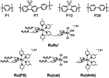
A potential strategy to achieve Z-scheme architecture is hybridization of photocatalysts, i.e., semiconductor particles in conjunction with adsorbed metal complexes that are active for CO2 reduction.7 Particularly active binuclear metal complexes, so-called ‘supramolecular photocatalysts’, have been reported which are composed of two units of metal complexes, where one acts as a photosensitizer component and the other as the catalytically active centre for CO2 conversion.3,16–20 These photocatalysts can accomplish CO2 reduction efficiently with high selectivity and stability using visible light, which is driven by the rapid intramolecular electron transfer from the photosensitizer unit to the catalyst unit. For example, binuclear ruthenium(II) complexes (RuRu′ in Chart 1) are visible-light-responsive supramolecular photocatalysts for CO2 reduction with relatively high durability (turnover number (TON) > 3000) and high product selectivity (>90%) for formate.17,18 Beyond using supramolecular photocatalysts as a single component, hybrid photocatalysts incorporating semiconductor particles allow for the step-by-step photoexcitation of the semiconductor and the photosensitizer unit of the supramolecular photocatalyst via the Z-scheme mechanism, thereby emulating natural photosynthesis.7 The hybrid photocatalysts can ensure both efficient CO2 reduction involving the supramolecular photocatalyst unit and extra driving force for the photogenerated hole scavenging process involving the semiconductor unit due to the increased oxidation power of a hybrid system. A representative example of a hybrid photocatalyst system was recently reported, assembled from silver-loaded carbon nitride as the semiconductor and RuRu′ as the supramolecular photocatalyst. This system has a turnover number for formate production (TONformate) of 50![[thin space (1/6-em)]](https://www.rsc.org/images/entities/char_2009.gif) 000 based on the loaded amount of RuRu′.15,21 To the best of our knowledge, this TON is the highest value reported to date (involving a photocatalytic CO2 reduction system with a 1
000 based on the loaded amount of RuRu′.15,21 To the best of our knowledge, this TON is the highest value reported to date (involving a photocatalytic CO2 reduction system with a 1![[thin space (1/6-em)]](https://www.rsc.org/images/entities/char_2009.gif) :
:![[thin space (1/6-em)]](https://www.rsc.org/images/entities/char_2009.gif) 1 ratio of a photosensitizer unit and a catalyst unit).
1 ratio of a photosensitizer unit and a catalyst unit).
Recently, conjugated polymers have emerged as visible-light-responsive semiconductor photocatalysts which allow excellent systematic control of chemical and optoelectronic properties through the rational choice of building blocks, i.e., the structure of the monomers.22–29 In particular, conjugated polymers containing dibenzo[b,d]thiophene sulfone units are amongst the most active materials in the literature for visible-light-driven sacrificial hydrogen production from water using particulate photocatalysts,25,27 and have even been reported to achieve overall water splitting when loaded with metal cocatalysts.30 There are also a few recent reports of photocatalytic CO2 reduction with conjugated polymers.31–33 However, the activity and selectivity values reported are low (apparent quantum yield (AQY) values of less than 0.5% and selectivity for CO2 reduction <75% relative to proton reduction).
Herein, we report a series of Z-scheme hybrid photocatalysts combining silver loaded conjugated polymer particles and the supramolecular photocatalyst RuRu′. Remarkably, the hybrid photocatalyst using poly(dibenzo[b,d]thiophene sulfone (P10) (RuRu′/Ag/P10, Scheme 1) showed unprecedented photocatalytic activity for CO2 reduction to formate (TONformate = 349![[thin space (1/6-em)]](https://www.rsc.org/images/entities/char_2009.gif) 000 ± 9000 and turnover frequency (TOFformate) = 6.5 s−1 based on the amount of RuRu′ adsorbed, and AQY for formate production = 11.2% at 440 nm). By using this photocatalytic system, all CO2 introduced into the reaction vessel at the beginning of the experiment could be converted selectively to formate, demonstrating the conversion was achieved even at very low concentrations of CO2. The production of formate could be further increased by periodical replenishment of CO2 to obtain highly concentrated formate solutions of up to 0.40 M within the timeframe studied and without significant degradation of the hybrid photocatalyst. This combination of activity and stability are especially relevant for practical application, considering that 1 liter of a 0.40 M formate solution could provide 9.9 liters of hydrogen when acidified.10,34,35
000 ± 9000 and turnover frequency (TOFformate) = 6.5 s−1 based on the amount of RuRu′ adsorbed, and AQY for formate production = 11.2% at 440 nm). By using this photocatalytic system, all CO2 introduced into the reaction vessel at the beginning of the experiment could be converted selectively to formate, demonstrating the conversion was achieved even at very low concentrations of CO2. The production of formate could be further increased by periodical replenishment of CO2 to obtain highly concentrated formate solutions of up to 0.40 M within the timeframe studied and without significant degradation of the hybrid photocatalyst. This combination of activity and stability are especially relevant for practical application, considering that 1 liter of a 0.40 M formate solution could provide 9.9 liters of hydrogen when acidified.10,34,35
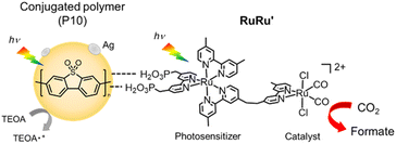 | ||
| Scheme 1 Photocatalytic CO2 reduction using hybrid photocatalysts, with conjugated polymer P10 as an example. | ||
2 Results and discussion
2.1 Synthesis of the hybrid photocatalysts
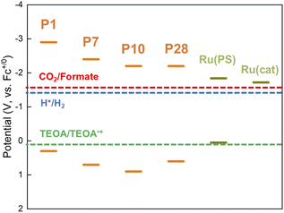
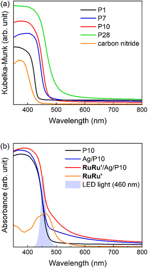
Conjugated polymers P1, P7, P10 and P28 (Chart 1) were synthesized via Suzuki–Miyaura polycondensation and purified using previously reported methods (see ESI and Fig. S1† for FT-IR spectra).25 For comparison the widely studied nanosheet-type carbon nitride was also synthesized using urea as a precursor by previously reported methods.21Table 1 and Fig. 1 summarize the predicted ionization potential (IP) and electron affinity (EA) values of the conjugated polymers which were obtained using density functional theory (DFT) using a previously developed approach36,37 and converted to a scale relative to the ferrocene redox couple (see Experimental section and ESI for calculation details and results in Table S1†). The potentials of the relevant solution reactions were also predicted (Table S2†) and in each case the polymers are predicted to have sufficient thermodynamic driving force to oxidize the sacrificial electron donor triethanolamine (TEOA) and reduce protons to hydrogen and CO2 to formate. Each polymer considered was also predicted to permit electron donation from the photoexcited polymers to the photosensitizer component as well as the catalytic component of RuRu′, whilst based on the predicted solution potentials the catalytic component of RuRu′ also has sufficient driving force for CO2 reduction to formate (the energy levels of RuRu′ were previously measured by cyclic voltammetry in the literature38). Fig. 2a shows the UV-vis diffuse reflectance spectra (DRS) of the conjugated polymers and carbon nitride. The UV-vis absorption spectrum of RuRu′ dissolved in acetonitrile is also shown in Fig. 2b. All of the conjugated polymers studied absorb in the visible region and have optical gaps extracted using Tauc plots in this region of the spectrum (Eo, Table 1, Fig. S2†). In the case of P10, as a typical example, it can absorb visible light up to 500 nm (optical gap of 2.64 eV). As expected, the experimental optical gap values of the conjugated polymers are correlated with the predicted fundamental gaps of the polymers (Ef, the difference between the ionization potential, IP, and electron affinity, EA, Table 1), where the optical gap is always smaller than the fundamental gap because of the non-negligible exciton binding energy for conjugated polymers.39
| Polymers (PX) | E o (eV) | IPb (V) | EAc (V) | E f (eV) | Products (5 h)/μmol | TONformate (5 h) | η formate (5 h)/% | TONformate (24 h) | |||||||||||||||||||||||||||||||||||||||||||||||||||||||||||||||||||||||||||||||||||||||||||
|---|---|---|---|---|---|---|---|---|---|---|---|---|---|---|---|---|---|---|---|---|---|---|---|---|---|---|---|---|---|---|---|---|---|---|---|---|---|---|---|---|---|---|---|---|---|---|---|---|---|---|---|---|---|---|---|---|---|---|---|---|---|---|---|---|---|---|---|---|---|---|---|---|---|---|---|---|---|---|---|---|---|---|---|---|---|---|---|---|---|---|---|---|---|---|---|---|---|---|---|
| Formate | CO | H2 | |||||||||||||||||||||||||||||||||||||||||||||||||||||||||||||||||||||||||||||||||||||||||||||||||
a Reaction conditions. Photocatalyst: 4 mg (RuRu′ loading: 0.4 μmol g−1; Ag loading: 1 wt%); solution: 4 mL of DMA/TEOA (4![[thin space (1/6-em)]](https://www.rsc.org/images/entities/char_2009.gif) : :![[thin space (1/6-em)]](https://www.rsc.org/images/entities/char_2009.gif) 1, v/v) bubbled with CO2; light source: 460 nm-centered LED with 5 mW output.
b DFT predicted ionization potential (V, vs. Fc+/0) of the polymers.
c DFT predicted electron affinity (V, vs. Fc+/0) of the polymers.
d 410 nm-centered LED with 5 mW output was used additionally involving hybrid photocatalysts based on P1 and carbon nitride. 1, v/v) bubbled with CO2; light source: 460 nm-centered LED with 5 mW output.
b DFT predicted ionization potential (V, vs. Fc+/0) of the polymers.
c DFT predicted electron affinity (V, vs. Fc+/0) of the polymers.
d 410 nm-centered LED with 5 mW output was used additionally involving hybrid photocatalysts based on P1 and carbon nitride.
|
|||||||||||||||||||||||||||||||||||||||||||||||||||||||||||||||||||||||||||||||||||||||||||||||||||
| P1d | 2.88 | 0.3 | −2.9 | 3.2 | 1.1 | 0.05 | 4.3 | 670 | 20 | 2300 | |||||||||||||||||||||||||||||||||||||||||||||||||||||||||||||||||||||||||||||||||||||||||
| P7 | 2.74 | 0.7 | −2.4 | 3.1 | 27 | 0.09 | 4.5 | 17![[thin space (1/6-em)]](https://www.rsc.org/images/entities/char_2009.gif) 000 000 |
86 | 52![[thin space (1/6-em)]](https://www.rsc.org/images/entities/char_2009.gif) 000 000 |
|||||||||||||||||||||||||||||||||||||||||||||||||||||||||||||||||||||||||||||||||||||||||
| P10 | 2.64 | 0.9 | −2.2 | 3.1 | 67 ± 4.1 | 0.14 ± 0.06 | 2.7 ± 0.3 | 42![[thin space (1/6-em)]](https://www.rsc.org/images/entities/char_2009.gif) 000 ± 2600 000 ± 2600 |
96 ± 0.2 | 140![[thin space (1/6-em)]](https://www.rsc.org/images/entities/char_2009.gif) 000 000 |
|||||||||||||||||||||||||||||||||||||||||||||||||||||||||||||||||||||||||||||||||||||||||
| P28 | 2.58 | 0.6 | −2.2 | 2.8 | 2.7 | N.D. | 0.42 | 1700 | 87 | 4200 | |||||||||||||||||||||||||||||||||||||||||||||||||||||||||||||||||||||||||||||||||||||||||
| Carbon nitrided | 2.99 | — | — | — | 5.4 ± 0.14 | N.D. | 0.42 ± 0.01 | 3400 | 97 | 13![[thin space (1/6-em)]](https://www.rsc.org/images/entities/char_2009.gif) 000 000 |
|||||||||||||||||||||||||||||||||||||||||||||||||||||||||||||||||||||||||||||||||||||||||
As a typical preparation method of the hybrid photocatalysts using P10 as an example, silver nanoparticles were loaded onto the polymer by impregnation using a silver nitrate precursor and subsequent heating under a hydrogen stream at 473 K. Transmission electron microscopy (TEM) images and energy dispersive X-ray spectroscopy (EDS) analysis of P10 before and after the Ag loading procedure clearly indicated that Ag particles were deposited on P10 (Fig. S3–S5†). EDS mapping analysis of the Ag-loaded P10 (Ag/P10) showed that Ag nanoparticles smaller than 50 nm decorated the surface of P10 (Fig. 3, S5 and S6†). RuRu′ was adsorbed onto the Ag/P10 particles by dispersing them in an acetonitrile (MeCN) solution containing dissolved RuRu′ with stirring overnight in the dark to obtain the hybrid photocatalyst (RuRu′/Ag/P10). No changes in the FT-IR spectra and the optical absorption edge of P10 were found after loading P10 with Ag and RuRu′ indicating that no changes to the structure of the polymer occurred (Fig. S7† and 2b). After the adsorption of RuRu′, the CO stretching bands of the Ru catalyst unit appeared in the FT-IR spectrum (Fig. 4a), and the metal-to-ligand-charge-transfer (1MLCT) absorption of the Ru photosensitizer unit of RuRu′ in the UV-vis absorption spectrum of the MeCN solution disappeared after filtering the solid materials (Fig. 4b).
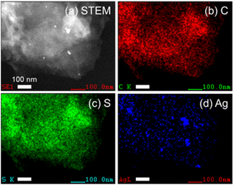 | ||
| Fig. 3 STEM image of Ag/P10 (a) and energy dispersive X-ray spectroscopy (EDS) mapping analysis showing the (b) carbon (c) sulfur and (d) silver elemental distributions. The scale bar indicates 100 nm. The EDS spectrum for the mapping images is shown in Fig. S6.† | ||
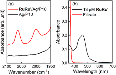 | ||
| Fig. 4 Adsorption of RuRu′ onto Ag/P10 to form hybrid photocatalyst RuRu′/Ag/P10. (a) FT-IR spectra of RuRu′/Ag/P10 and Ag/P10 at the region of CO stretching bands obtained in the diffuse reflectance configuration. The loading amount of RuRu′ is 10 μmol g−1. The spectra in wide wavenumber range are shown in Fig. S7.† (b) UV-vis absorption spectra of MeCN solution containing 13 μM RuRu′ and the filtrate solution after the adsorption of RuRu′ onto Ag/P10 to obtain RuRu′ (10 μmol g−1)/Ag/P10. | ||
These observations demonstrate a very strong adsorption affinity between the RuRu′ supramolecular photocatalyst and the semiconductor Ag/P10. Fig. 2b shows the DRS of P10, Ag/P10 and RuRu′/Ag/P10, and the UV-vis absorption spectrum of RuRu′ in acetonitrile solution. Incorporation of Ag and RuRu′ increased the absorption into a wider range of the visible region from 470 to 800 nm, which was attributed to plasmon absorption of the Ag particles21,40,41 and to metal-to-ligand charge transfer absorption bands of the Ru photosensitizer unit of RuRu′, respectively. It further indicates successful loading of Ag and RuRu′ onto P10. The other hybrid photocatalysts were prepared using the same procedures (RuRu′/Ag/P1, RuRu′/Ag/P7, RuRu′/Ag/P28 and RuRu′/Ag/carbon nitride), of which the DRS traces are shown in Fig. S8.†
We investigated the adsorption ability of Ru(PS) (Chart 1), which is a model mononuclear complex of the Ru photosensitizer unit with the methyl phosphonic acid groups, onto the conjugated polymers. The conjugated polymer powders were dispersed in an acetonitrile solution containing Ru(PS) in the dark for 3 days. Subsequently, the adsorbed amount of Ru(PS) was determined by the decrease of the 1MLCT adsorption of Ru(PS) in the filtrate solution after the adsorption.15,20Fig. 5a shows the degree of adsorption of Ru(PS) onto the conjugated polymers according to the increase in the added Ru(PS) amount. P10 and P7 demonstrated much higher adsorption affinities for Ru(PS) compared to P1 and P28. P10 demonstrated ideal adsorption up to 50 μmol g−1 and reached 60 μmol g−1 adsorption, while P7 demonstrated a smaller maximum adsorption (42 μmol g−1) than P10. In the case of P1 and P28, the maximum adsorption amounts were 15.7 μmol g−1 and 11.8 μmol g−1, respectively. These results indicate that the sulfone groups of P10 and P7 act as adsorption sites of RuRu′ through interaction with the methyl phosphonic acid anchors, whereas phenylene and pyrazine units do not show the same degree of affinity to the methyl phosphonic acid groups. The observation of a potential strong interaction of sulfone units with the methyl phosphonic acid anchors was also supported by the much lower adsorption of Ru(dmb) (Chart 1) onto P10, which is a model complex of the photosensitizer unit without the methyl phosphonic acid groups (the maximum absorption was 9.8 μmol g−1 in this case, Fig. 5b).
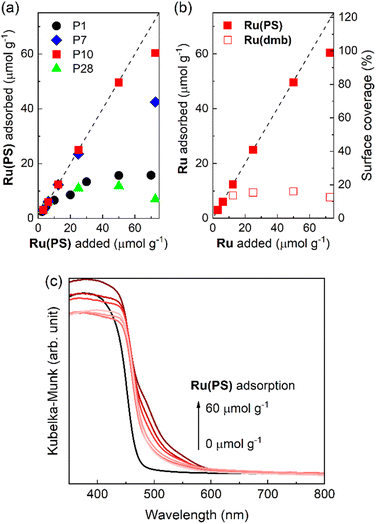 | ||
| Fig. 5 (a) Adsorption of the ruthenium photosensitizer model complex (Ru(PS)) onto the conjugated polymers with increasing amounts of Ru(PS). (b) Adsorption of the ruthenium photosensitizer model complexes (Ru(PS) and Ru(dmb)) onto P10 with increasing amounts of ruthenium photosensitizer molecules. The dashed lines indicate ideal (100%) adsorption of the ruthenium photosensitizer molecules as a guide. (c) Diffuse reflectance absorption spectra of Ru(PS) adsorbed-P10 corresponding to the adsorption of Ru(PS) in Fig. 5a. | ||
We then calculated the surface coverage of the adsorbed Ru(PS) on P10. Assuming uniform monolayer adsorption of Ru(PS) onto P10 and by using the Brunauer–Emmett–Teller (BET) surface area of P10 (35 m2 g−1) obtained from a N2 adsorption–desorption isotherm (Fig. S9†) and the diameter of Ru(PS) (1.1 nm) obtained from a MM2 calculation,20 the surface coverage of Ru(PS) on P10 was calculated to be nearly quantitative at the maximum adsorption (98.7%). The incorporation of Ru(PS) onto P10 was confirmed by the increase in the adsorption that is assigned to the 1MLCT excitation of Ru(PS) in the diffuse reflectance spectra of Ru(PS)-adsorbed P10 as shown in Fig. 5c.
2.2 Photocatalytic CO2 reduction using the hybrid photocatalysts
Photocatalytic CO2 reduction reactions were performed with suspensions of the hybrid photocatalysts particles in a N,N′-dimethylacetamide (DMA)/triethanolamine (TEOA) (4![[thin space (1/6-em)]](https://www.rsc.org/images/entities/char_2009.gif) :
:![[thin space (1/6-em)]](https://www.rsc.org/images/entities/char_2009.gif) 1, v/v) mixture after sonication, while the suspension was stirred under a CO2 atmosphere in a sealed reaction vessel during irradiation. TEOA was used as a sacrificial electron donor and a proton source, while DMA acted as a solvent dispersing the hybrid photocatalysts well. Based on the DRS traces of the conjugated polymers and the absorption spectrum of RuRu′ (Fig. 2), LED light centered at 460 nm was selected for photocatalytic reactions using hybrid systems including P7, P10, and P28 because these materials and the supramolecular photocatalyst RuRu′ can be excited at this wavelength. In the case of RuRu′/Ag/P1 and RuRu′/Ag/carbon nitride, additional LED light centered at 410 nm was also used to excite these semiconductors (Fig. S10†).
1, v/v) mixture after sonication, while the suspension was stirred under a CO2 atmosphere in a sealed reaction vessel during irradiation. TEOA was used as a sacrificial electron donor and a proton source, while DMA acted as a solvent dispersing the hybrid photocatalysts well. Based on the DRS traces of the conjugated polymers and the absorption spectrum of RuRu′ (Fig. 2), LED light centered at 460 nm was selected for photocatalytic reactions using hybrid systems including P7, P10, and P28 because these materials and the supramolecular photocatalyst RuRu′ can be excited at this wavelength. In the case of RuRu′/Ag/P1 and RuRu′/Ag/carbon nitride, additional LED light centered at 410 nm was also used to excite these semiconductors (Fig. S10†).
Table 1 summarizes the products of the photocatalytic reactions after 5 hours using hybrid photocatalysts with an RuRu′ loading of 0.4 μmol g−1. In the RuRu′/Ag/P10 system formate was produced as the main product (67 ± 4.1 μmol) with only a trace amount of CO (Fig. 6a), with a TONformate of 42![[thin space (1/6-em)]](https://www.rsc.org/images/entities/char_2009.gif) 000 ± 2600 based on the amount of RuRu′ adsorbed. Although hydrogen was also formed as a minor product, the amount (2.7 ± 0.3 μmol) was much less than that of formate. RuRu′/Ag/P10 thus has a high selectivity for formate (ηformate) of 96 ± 0.2%. RuRu′/Ag/P7 also performed well as a photocatalyst for CO2 reduction, but its photocatalytic activity, i.e., TONformate and ηformate, was lower than that of RuRu′/Ag/P10.
000 ± 2600 based on the amount of RuRu′ adsorbed. Although hydrogen was also formed as a minor product, the amount (2.7 ± 0.3 μmol) was much less than that of formate. RuRu′/Ag/P10 thus has a high selectivity for formate (ηformate) of 96 ± 0.2%. RuRu′/Ag/P7 also performed well as a photocatalyst for CO2 reduction, but its photocatalytic activity, i.e., TONformate and ηformate, was lower than that of RuRu′/Ag/P10.
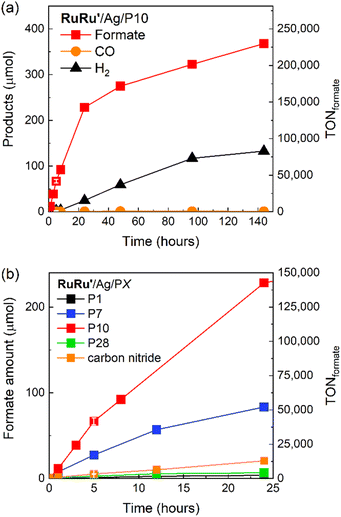 | ||
Fig. 6 (a) Products of photocatalytic CO2 reduction and corresponding TONformate during light irradiation using RuRu′/Ag/P10. (b) Photocatalytic CO2 reduction to formate with corresponding TONformate using the series of hybrid photocatalysts studied (RuRu′/Ag/PX). Hybrid photocatalysts (4 mg loaded with 1 wt% Ag and 0.4 μmol per g RuRu′) were dispersed in 4 mL of DMA/TEOA (4![[thin space (1/6-em)]](https://www.rsc.org/images/entities/char_2009.gif) : :![[thin space (1/6-em)]](https://www.rsc.org/images/entities/char_2009.gif) 1 v/v), bubbled with CO2 and irradiated at λexmax = 460 nm with a LED (5 mW output power). An additional LED at 410 nm with 5 mW output was used to excite the semiconductor in the case of RuRu′/Ag/P1 and RuRu′/Ag/carbon nitride due to their larger optical gaps (see Fig. 1a). The total product formation for the other hybrid photocatalysts, akin to the P10 hybrid photocatalyst in Fig. 6a, is shown in Fig. S11.† 1 v/v), bubbled with CO2 and irradiated at λexmax = 460 nm with a LED (5 mW output power). An additional LED at 410 nm with 5 mW output was used to excite the semiconductor in the case of RuRu′/Ag/P1 and RuRu′/Ag/carbon nitride due to their larger optical gaps (see Fig. 1a). The total product formation for the other hybrid photocatalysts, akin to the P10 hybrid photocatalyst in Fig. 6a, is shown in Fig. S11.† | ||
On the other hand, the photocatalytic activities of the hybrid photocatalysts using the pyrazine-containing polymer (RuRu′/Ag/P28) and the phenylene-containing polymer (RuRu′/Ag/P1), both containing no sulfone groups, were at least ten times lower compared to the hybrid photocatalysts based on sulfone-containing polymers (RuRu′/Ag/P10 and RuRu′/Ag/P7). These trends in photocatalytic activity were maintained over longer light irradiation up to 24 hours (Fig. 6b and S11†). The differences observed in the photocatalytic activity of these hybrid systems are discussed in more detail in the mechanism section. It is noteworthy that the photocatalytic activities of the hybrid systems using sulfone-containing polymers (P10 and P7) were much higher than that of carbon nitride (especially P10 which shows a more than ten times higher activity), especially when considering that carbon nitride has frequently been used as a polymer photocatalyst showing high activity in its own right.21
Since the photocatalytic activity of RuRu′/Ag/P10 was far superior to the other hybrid photocatalysts, we focused on this photocatalytic system. Isotope labelling experiments with 13CO2 clearly showed that the formate produced in the photocatalytic reaction was from CO2 (Fig. S12†). Long term irradiation experiments were conducted to investigate the stability of the hybrid photocatalyst (Fig. 6a). The photocatalytic activity continued for up to 6 days, 144 hours of irradiation produced 368 μmol of formate corresponding to a TONformate of 230![[thin space (1/6-em)]](https://www.rsc.org/images/entities/char_2009.gif) 000. Hydrogen evolution increased over this time period as well, leading the ηformate to decrease to 73% after 6 days. The total quantity of CO2 within the reaction vessel (gas phase and the solution) before irradiation was estimated to be 737 μmol (see Experimental section). Hence, we noticed that during this time period, almost 50% of the CO2 in the reaction vessel was converted to formate. This result clearly highlights not only the very high photocatalytic activity of RuRu′/Ag/P10, but also its remarkable stability.
000. Hydrogen evolution increased over this time period as well, leading the ηformate to decrease to 73% after 6 days. The total quantity of CO2 within the reaction vessel (gas phase and the solution) before irradiation was estimated to be 737 μmol (see Experimental section). Hence, we noticed that during this time period, almost 50% of the CO2 in the reaction vessel was converted to formate. This result clearly highlights not only the very high photocatalytic activity of RuRu′/Ag/P10, but also its remarkable stability.
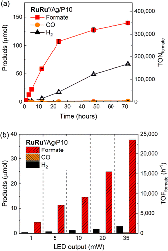
To evaluate the maximum TONformate, a smaller amount of RuRu′/Ag/P10 (1 mg) was used instead of the 4 mg that was used for Fig. 6a. Formate was produced linearly up to 24 hours of photoirradiation, and subsequently the production rate of formate gradually decreased accompanied with an increase in hydrogen production (Fig. 7a). After 72 hours of irradiation, the TONformate reached 349![[thin space (1/6-em)]](https://www.rsc.org/images/entities/char_2009.gif) 000 ± 9
000 ± 9![[thin space (1/6-em)]](https://www.rsc.org/images/entities/char_2009.gif) 000 (140 ± 3.6 μmol), which exceeded the highest TON reported among the hybrid photocatalysts for CO2 reduction by a factor of almost 7 times (TON = 50
000 (140 ± 3.6 μmol), which exceeded the highest TON reported among the hybrid photocatalysts for CO2 reduction by a factor of almost 7 times (TON = 50![[thin space (1/6-em)]](https://www.rsc.org/images/entities/char_2009.gif) 000 for the previous highest).15 The durability is also much higher compared to that of a homogeneous system using RuRu′ (0.05 mM), which demonstrated TONformate = 1600 after 20 hours of irradiation (Fig. S13†) using a stronger reductant, 1,3-dimethyl-2-(o-hydroxyphenyl)-2,3-dihydro-1H-benzo[d]imidazole (BI(OH)H), since TEOA cannot thermodynamically quench the excited photosensitizer unit of RuRu′.3 These comparisons clearly demonstrate that the combination of Ag/P10 and the supramolecular complex significantly increases the durability of RuRu′ for photocatalytic CO2 reduction.
000 for the previous highest).15 The durability is also much higher compared to that of a homogeneous system using RuRu′ (0.05 mM), which demonstrated TONformate = 1600 after 20 hours of irradiation (Fig. S13†) using a stronger reductant, 1,3-dimethyl-2-(o-hydroxyphenyl)-2,3-dihydro-1H-benzo[d]imidazole (BI(OH)H), since TEOA cannot thermodynamically quench the excited photosensitizer unit of RuRu′.3 These comparisons clearly demonstrate that the combination of Ag/P10 and the supramolecular complex significantly increases the durability of RuRu′ for photocatalytic CO2 reduction.
After the photocatalytic reaction as shown in Fig. 7a, RuRu′/Ag/P10 showed no significant changes in its FT-IR spectra (Fig. S14a†), UV/vis diffuse reflectance spectra (Fig. S14b†), or Ag 3d X-ray photoelectron spectroscopy (XPS) spectra when comparing a sample before and after irradiation (Fig. S14c†). This strongly suggests that the structural and optoelectronic properties of P10 and Ag remained unaffected. After 24 hours of irradiation, desorbed RuRu′ was observed in the reaction solution, which was determined to be around 15% of the initially loaded RuRu′ in RuRu′/Ag/P10, as estimated by inductively coupled plasma optical emission spectroscopy (ICP-OES) measurements. This partial detachment of RuRu′ from the semiconductor surface is likely to contribute to the increased hydrogen evolution rate as well as the slowing down of formate production. This increase in hydrogen production upon desorption of RuRu′ is in line with the literature reporting P10 as an efficient photocatalyst for hydrogen evolution under visible light irradiation in the presence of a sacrificial hole scavenger.25 When the reactor was saturated with CO2 again after 24 hours and 48 hours of irradiation, and when the hybrid photocatalyst was recycled after 24 hours of irradiation with fresh DMA/TEOA solution and CO2 bubbling, no significant increase in formate production was observed compared to that without additional replenishment (Fig. S15†). This demonstrates that the shortage of CO2 or TEOA is not significantly influencing the photocatalytic activity in this measured timeframe.
Fig. 7b shows the light intensity dependence associated with the rate of formate production, i.e., the turnover frequency (TOFformate). Up to the maximum output of the used LED, the TOFformate linearly increased in proportion to the light intensity, and the observed maximum TOFformate reached 23![[thin space (1/6-em)]](https://www.rsc.org/images/entities/char_2009.gif) 500 h−1 (6.5 s−1) based on the amount of RuRu′ loaded onto the material. This activity is 8 times higher compared to the highly efficient homogeneous system using the Ru(II)–Ru(II) supramolecular photocatalyst without methyl phosphonic anchor groups (TOFformate = 0.2–0.8 s−1),17,18 highlighting the inherent very fast catalytic rate of the Ru catalyst unit in RuRu′/Ag/P10. We note that this TOF was obtained using a light source with limited light intensity, therefore this is probably not the potential maximum value for the TOF. Interestingly, the measured TOFformate is even larger than that for CO2 fixation by ribulose-1,5-bisphosphate carboxylase/oxygenase (RuBisCO) in natural photosynthesis (3.3 s−1),42 albeit the two values cannot be compared directly.
500 h−1 (6.5 s−1) based on the amount of RuRu′ loaded onto the material. This activity is 8 times higher compared to the highly efficient homogeneous system using the Ru(II)–Ru(II) supramolecular photocatalyst without methyl phosphonic anchor groups (TOFformate = 0.2–0.8 s−1),17,18 highlighting the inherent very fast catalytic rate of the Ru catalyst unit in RuRu′/Ag/P10. We note that this TOF was obtained using a light source with limited light intensity, therefore this is probably not the potential maximum value for the TOF. Interestingly, the measured TOFformate is even larger than that for CO2 fixation by ribulose-1,5-bisphosphate carboxylase/oxygenase (RuBisCO) in natural photosynthesis (3.3 s−1),42 albeit the two values cannot be compared directly.
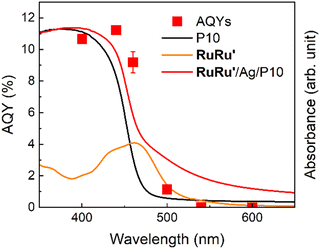
Fig. 8 displays the action spectra obtained by measuring apparent quantum yields for formate production (AQYformate, the red squares), which is defined as eqn (1),4,43 under light irradiation at various wavelength.
| AQYformate = (Total formation of formate)/(total number of incident photons) × 100 | (1) |
The highest AQYformate was 11.2% under irradiation at λmax = 440 nm. This AQYformate value of RuRu′/Ag/P10 is the highest in the reported visible-light-driven hybrid photocatalytic CO2 reduction systems composed of semiconductors and metal complex catalysts (Table S3†), and twice higher even compared to that of the previously reported highest AQY.44
It is noteworthy that the photosensitizer unit of RuRu′ has the 1MLCT absorption around at 460 nm (orange line) and the absorption of P10 becomes weaker over 400 nm (black line). In this action spectra, AQYformate under irradiation at λmax = 440 nm (which can be efficiently absorbed by both P10 and the Ru photosensitizer unit) shows the highest value (11.2%). Interestingly, under irradiation at λmax = 400 nm, which was more strongly absorbed by P10 but less absorbed by the Ru photosensitizer compared to those under irradiation at λmax = 440 nm, AQYformate was 10.7%, i.e., similar to but slightly less than AQY under irradiation at λmax = 440 nm. In addition, under irradiation at λmax = 460 nm, which is efficiently absorbed by the Ru photosensitizer unit but absorption by P10 is fairly weaker, AQYformate was 9.2%, slightly less than that under irradiation at λmax = 440 nm but still produced a very high value. The AQYformate value drastically decreased at 500 nm, which cannot be efficiently absorbed by either P10 or the Ru photosensitizer, and the hybrid system does not work over 540 nm which cannot be absorbed by the hybrid photocatalytic system at all. These results indicate that some of the photocatalytic CO2 reduction proceeded by the mechanism involving the Z-scheme type electron transfer via sequential light absorption by P10 and the Ru photosensitizer unit of RuRu′.
2.3 Quantitative CO2 conversion to highly concentrated formate solution using the RuRu′/Ag/P10 photocatalyst
For the practical application of photocatalytic CO2 reduction as a renewable and sustainable source of formic acid, the following two requirements are important: production of highly concentrated solutions of formic acid; and high conversion rates of CO2 in the reaction system (particularly in an environment where only low concentrations of CO2 are present). High photocatalytic conversion of CO2 to CO has been reported very recently, although large quantities of the photocatalyst would be necessary to obtain significantly large amounts of CO owing to the durability of the system (TONCO = 2400).45 Incidentally, no photocatalytic systems have been reported that achieve CO2 conversion to formate at concentrations suitable for application. Since RuRu′/Ag/P10 shows very high efficiency and durability, we studied the system for the production of highly concentrated solutions of formate.A sealed reaction vessel containing RuRu′/Ag/P10 (8 mg, loaded with 10 μmol per g RuRu′) dispersed in 4 mL of DMA/TEOA (4![[thin space (1/6-em)]](https://www.rsc.org/images/entities/char_2009.gif) :
:![[thin space (1/6-em)]](https://www.rsc.org/images/entities/char_2009.gif) 1, v/v) with 5.75 mL of the gaseous phase (1 atm) being filled with CO2 by bubbling for 20 minutes, was irradiated using an LED light source at 460 nm. After irradiation for 120 hours, the amount of formate produced reached 737 ± 8.60 μmol (TONformate = 18
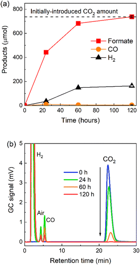
1, v/v) with 5.75 mL of the gaseous phase (1 atm) being filled with CO2 by bubbling for 20 minutes, was irradiated using an LED light source at 460 nm. After irradiation for 120 hours, the amount of formate produced reached 737 ± 8.60 μmol (TONformate = 18![[thin space (1/6-em)]](https://www.rsc.org/images/entities/char_2009.gif) 400) with a small amount of hydrogen and a trace amount of CO (Fig. 9a).
400) with a small amount of hydrogen and a trace amount of CO (Fig. 9a).
The amount of formate produced was determined to be the molar equivalent of the initial loading of CO2 in the sealed reaction vessel before irradiation (737 μmol, 16.5 mL, see Experimental section and ESI† for more detail). This result demonstrates that the quantitative conversion of CO2 to formate was observed. The complete molar consumption of CO2 under irradiation was also confirmed by gas chromatography (GC, Fig. 9b). The CO2 peak in the chromatogram decreased gradually over the measured time period until, after 120 hours, 99.5 ± 0.2% of the initial CO2 was consumed (according to the measured GC signal area). To the best of our knowledge, this is the first report of a photocatalytic system that facilitates complete light-driven conversion of CO2 to formate at standard temperature and pressure.
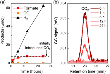
The photocatalytic reduction of CO2 using RuRu′/Ag/P10 proceeded even under an Ar atmosphere containing 1% of CO2, in which CO2 was quantitatively converted to formate (Fig. 10a). The peak attributed to CO2 in the gas chromatogram decreased during the light irradiation and was finally below the detection limit after 12 hours of irradiation. This confirmed that full consumption of the contained CO2 in the reaction vessel was possible even under very low concentrations of CO2 (Fig. 10b). These results have broad implications: it is very important to enable CO2 conversion at low concentrations (as opposed to high purity CO2 sources, in which enrichment of low concentration CO2 would require high energy and cost) since typical flue gas mixtures from the industrial sector contain relatively low concentrations of CO2 (typically between 3–13%).
We recently reported the direct reduction of CO2 at low concentrations using a Re(I) diimine tricarbonyl complex with a deprotonated TEOA ligand that can capture CO2 to form a carbonate ester complex via a CO2 insertion reaction between the deprotonated TEOA and the Re(I) center, and as such even with progressively lowering CO2 concentrations, the molecules can still efficiently accumulate into the Re complex owing to the large equilibrium constant associated with the formation of the CO2 adduct (Scheme S1†).46 Indeed, applications of this CO2 capturing reaction in photocatalytic and electrocatalytic reduction of low concentration CO2 have already been reported.47,48 Mn(I) complexes with similar structures also have this ability to capture CO2.49 In this work, we are reporting the first example of a photocatalyst based on a [Ru(diimine)(CO)2Cl2]-type complex which can reduce CO2 at low concentrations akin to the Re(I)-complex, however in this case the Ru(II)-complex is formate selective whilst the Re(I)-complex is CO selective. The reduction mechanism of low concentration CO2 on the Ru catalyst is currently under investigation in our laboratory.
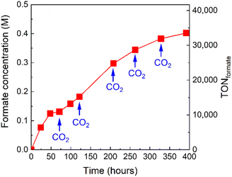
The formate concentration in the solution after the complete conversion of CO2 (Fig. 9a) was 0.18 M. Taking advantage of the high stability of the photocatalytic system, we sought to further increase the concentration of formate in the reaction solution by repeated CO2 replenishment. A photocatalytic reaction of RuRu′/Ag/P10 was set up and irradiated. After irradiation for 71, 122, 208, 263, and 328 hours, CO2 was bubbled through the mixture to replenish to the initial concentration. Formate production continuously increased and the final concentration of formate in the solution reached up to 0.40 M after approximately 400 hours corresponding to a TONformate = 33![[thin space (1/6-em)]](https://www.rsc.org/images/entities/char_2009.gif) 500 (Fig. 11).
500 (Fig. 11).
Indeed, 1 liter of this solution is equivalent to 9.9 liters of hydrogen gas (under STP), thus the produced formate is already concentrated enough for use as a hydrogen carrier without energy-intensive concentration enrichment being required. The formic acid can then be used in dehydrogenation processes using homogeneous catalysts already reported.11–13 This is the first report of a visible-light-driven CO2 reduction process robust enough to produce highly concentrated formate as a product at standard temperature and pressure.
2.4 Mechanistic insights into the hybrid system
RuRu′/Ag/P10 demonstrated the best photocatalytic activity for CO2 reduction amongst the hybrid photocatalysts studied (Table 1 and Fig. 6b). The hybrid photocatalyst using the copolymer of phenylene and dibenzo[b,d]thiophene sulfone (P7) was also active for formate production with good product selectivity (>70%), which was also significantly better in terms of photocatalytic activity than the well-established hybrid photocatalyst based on carbon nitride. On the other hand, the photocatalytic activities of hybrid photocatalysts using the copolymer of pyrazine and phenylene (P28) and poly(p-phenylene) (P1) were much lower. When considering the inverse trends between the photocatalytic activity and driving force for electron transfer between the conjugated polymers and RuRu′ (Table 1 and Fig. 1), the energetic positioning of the conduction bands of the polymers (the EA energies in Table 1 with the decreasing order P1 > P7 > P10 ≈ P28) does not explain the observed photocatalytic activity of the hybrid photocatalysts, especially considering the clear superior performance of the sulfone-containing polymers in hybrid photocatalytic systems.One characteristic of sulfone-rich polymers, especially P10, is their previously reported high efficiency of generating photoexcited electrons under sacrificial conditions. This is governed at least in part by the deep lying IP (in turn governing the oxidation power of the semiconductor) which renders the sulfone-rich polymers as good electron accepting materials when photoexcited in the presence of easily oxidizable sacrificial reagents (Table 1 and Fig. 1). This property combined with increased dispersibility in the medium led to higher sacrificial hydrogen evolution rates observed in a previous study. Furthermore, transient absorption spectroscopy studies showed that the rate and persistence of polaron formation under sacrificial conditions was highest for P10, followed by P7 then P1 showing the lowest values, highlighting the superiority of P10 in producing photogenerated electrons in the presence of sacrificial reagents, at least relative to P7 and P1.24,25 As a last note on sulfone-rich polymers, it has also been suggested that photoexcited electrons accumulate and are utilized via the sulfone groups when tested for photocatalytic applications due to the electron-accepting property and dipole formation governed by the sulfone groups.24,29 Altogether, these factors are likely applicable to the photocatalytic activity observed in this work.
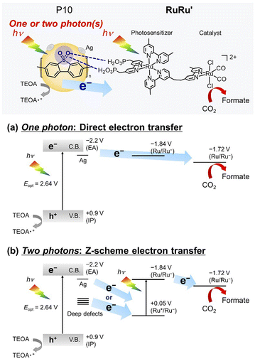
Specific to the photocatalytic application discussed in this work, another reason for the very high activity of the sulfone-containing polymers is a potentially strong interaction of the sulfone groups with the methyl phosphonic acid groups of RuRu′ as demonstrated in Fig. 5. This is likely to facilitate efficient transfer of the electrons accumulated on the sulfone groups to RuRu′ as well as suppressing the detachment of RuRu′ from the surface of the polymer (this is illustrated in the upper part of Scheme 2, and the potential role of silver is discussed in greater depth based on control experiments herein).
The roles of each component in the RuRu′/Ag/P10 system were studied first by performing control experiments (Table 2). In the absence of CO2 (entry 2), TEOA (entry 3), irradiation (entry 4), RuRu′ (entry 5), RuRu′ and Ag (entry 6), or Ag and P10 (entry 10), no CO2 reduction products were detected after one hour of irradiation, confirming that all components are necessary to observe any CO2 reduction activity. RuRu′/P10 without Ag loading (entry 7) showed significantly lower photocatalytic activity for CO2 reduction (TOFformate = 1.5 μmol h−1 and 46% selectivity for formate production) compared to RuRu’/Ag/P10 (entry 1) (TOFformate = 11 μmol h−1 and 94% selectivity). Although the hydrogen evolution rate of RuRu′/P10 (1.4 μmol) was higher than that by RuRu′/Ag/P10 (0.70 μmol), the total amount of the reduction products (formate, CO, and H2) by RuRu′/P10 (3.3 μmol) was much lower than that produced by RuRu′/Ag/P10 (12 μmol). These results suggest that the Ag loading enhances charge separation of photoexcited carriers produced by the excitation of P10 owing to electron capture by the Ag particles.50 Simultaneously, proton reduction (which occurs via electron transfer from the residual Pd clusters on P10 to protons) is significantly suppressed by photogenerated electrons residing on the Ag nanoparticles instead, potentially due to the higher overpotential of Ag for proton reduction compared to Pd.32 Indeed, it was previously reported that Ag loading in hybrid photocatalyst systems of metal-complex photocatalysts and semiconductors promotes charge separation and electron transfer from the semiconductor to the photocatalyst.21,50,51 Unlike carbon nitride which is made using metal-free synthetic procedures, the conjugated polymers are made using Pd-cross coupling reactions resulting in palladium residuals in the material (0.007 wt% Pd residuals in P10 in this study, which was estimated by ICP-OES measurement). The preference for photogenerated electrons to reside on Ag instead of Pd in the case of P10 is still an open question. Transient absorption spectroscopy studies inferred in the case of P10 that electron polarons tend to reside on the polymer rather than the residual Pd clusters (relative to the kinetics which catalytic reactions typically demand, i.e., electron transfer to residual Pd is slow). In contrast, other conjugated polymers such as F8BT (poly[(9,9-di-n-octylfluorenyl-2,7-diyl)-alt-(benzo[2,1,3]thiadiazol-4,8-diyl)]) readily accumulate charges on the residual palladium clusters with competitive kinetics to the typical timescale for catalytic events.52 This could be further reasoning as to why the P10 hybrid photocatalyst system works so efficiently and selectively, as the kinetic competition for electron accumulation on Ag nanoparticles is potentially greater relative to residual Pd, however we note that more detailed spectroscopy experiments to probe the mechanism here are required to elaborate further.
| Entry | Photocatalyst | Absence | Products/μmol | TOFformate/h−1 | Selectivityformate/% | ||||||||||||||||||||||||||||||||||||||||||||||||||||||||||||||||||||||||||||||||||||||||||||||
|---|---|---|---|---|---|---|---|---|---|---|---|---|---|---|---|---|---|---|---|---|---|---|---|---|---|---|---|---|---|---|---|---|---|---|---|---|---|---|---|---|---|---|---|---|---|---|---|---|---|---|---|---|---|---|---|---|---|---|---|---|---|---|---|---|---|---|---|---|---|---|---|---|---|---|---|---|---|---|---|---|---|---|---|---|---|---|---|---|---|---|---|---|---|---|---|---|---|---|---|
| Formate | CO | H2 | |||||||||||||||||||||||||||||||||||||||||||||||||||||||||||||||||||||||||||||||||||||||||||||||||
a Reaction conditions. Photocatalyst: 4 mg (RuRu′ loading: 0.4 μmol g−1; Ag loading: 1 wt%); solution: 4 mL of DMA/TEOA (4![[thin space (1/6-em)]](https://www.rsc.org/images/entities/char_2009.gif) : :![[thin space (1/6-em)]](https://www.rsc.org/images/entities/char_2009.gif) 1, v/v) bubbled with CO2; Light source: 460 nm-centered LED; reaction time: 1 hour.
b Under Ar atmosphere. 1, v/v) bubbled with CO2; Light source: 460 nm-centered LED; reaction time: 1 hour.
b Under Ar atmosphere.
|
|||||||||||||||||||||||||||||||||||||||||||||||||||||||||||||||||||||||||||||||||||||||||||||||||||
| 1 | RuRu′/Ag/P10 | — | 11.00 | N.D. | 0.70 | 7000 | 94 | ||||||||||||||||||||||||||||||||||||||||||||||||||||||||||||||||||||||||||||||||||||||||||||
| 2 | RuRu′/Ag/P10 | CO2b | N.D. | N.D. | 1.10 | — | — | ||||||||||||||||||||||||||||||||||||||||||||||||||||||||||||||||||||||||||||||||||||||||||||
| 3 | RuRu′/Ag/P10 | TEOA | N.D. | N.D. | N.D. | — | — | ||||||||||||||||||||||||||||||||||||||||||||||||||||||||||||||||||||||||||||||||||||||||||||
| 4 | RuRu′/Ag/P10 | Light | N.D. | N.D. | N.D. | — | — | ||||||||||||||||||||||||||||||||||||||||||||||||||||||||||||||||||||||||||||||||||||||||||||
| 5 | Ag/P10 | RuRu′ | N.D. | N.D. | 3.70 | — | — | ||||||||||||||||||||||||||||||||||||||||||||||||||||||||||||||||||||||||||||||||||||||||||||
| 6 | P10 | RuRu′ and Ag | N.D. | N.D. | 1.60 | — | — | ||||||||||||||||||||||||||||||||||||||||||||||||||||||||||||||||||||||||||||||||||||||||||||
| 7 | RuRu′/P10 | Ag | 1.50 | 0.35 | 1.40 | 930 | 46 | ||||||||||||||||||||||||||||||||||||||||||||||||||||||||||||||||||||||||||||||||||||||||||||
| 8 | Ru(cat)/Ag/P10 | Ru(PS) unit | 5.00 | N.D. | 1.20 | 3100 | 81 | ||||||||||||||||||||||||||||||||||||||||||||||||||||||||||||||||||||||||||||||||||||||||||||
| 9 | Ru(PS)/Ag/P10 | Ru(cat) unit | 0.34 | N.D. | 3.37 | 21 | 9.2 | ||||||||||||||||||||||||||||||||||||||||||||||||||||||||||||||||||||||||||||||||||||||||||||
| 10 | RuRu′ | Ag/P10 | N.D. | N.D. | N.D. | — | — | ||||||||||||||||||||||||||||||||||||||||||||||||||||||||||||||||||||||||||||||||||||||||||||
When a ruthenium mononuclear catalyst Ru(cat), which is a mononuclear model complex of the catalytic unit of RuRu′ (see Chart 1), was used instead of RuRu′ (Ru(cat)/Ag/P10, Table 1, entry 8), the resulting system was active for photocatalytic CO2 reduction. However, the production of formate after 1 hour of irradiation was less than half (5.0 μmol) than that of RuRu′/Ag/P10 (11 μmol) with a lower selectivity (ηformate = 81%, compared to 94% in the system using RuRu′/Ag/P10). These results strongly indicate that there are two possible electron injection pathways to the catalyst unit of RuRu′: direct electron injection from Ag/P10 to the catalyst unit without excitation of the photosensitizer unit (Scheme 2a); and the Z-scheme-type electron transfer (Scheme 2b). Since the reduction potential of the catalyst unit of RuRu′ (Ep = −1.72 V, vs. Fc+/0) is more positive compared to the potential of the conduction band of P10 (EA = −2.2 V, vs. Fc+/0) and probably to those of shallow defect sites as well, these high-energy electrons can directly transfer to the catalyst unit. Probably, on the other hand, electrons trapped in the deep defect sites of P10 and/or Ag/P10 cannot directly transfer to the catalyst unit but can transfer to the SOMO-2 of the excited photosensitizer unit ( , vs. Fc+/0). Indeed, these types of shallow and deep defect sites have already been reported in various semiconductor materials, including organic polymers.21,53,54 This pathway for relatively low-energy electrons through the Z-scheme mechanism is likely to be one of the reasons for the highly efficient and durable photocatalysis of RuRu′/Ag/P10. Such advantages of the Z-scheme mechanism have already been demonstrated in the hybrid photocatalyst system using plasma-treated carbon nitride, by which plasma treatment of the material formed deep defect sites which could accumulate photoexcited electrons and participate in the Z-scheme pathway.15
It has been reported that the one-electron reduced species of trans-(Cl)–[Ru(2,2′-bpy)(CO)2Cl2], that has a similar structure of the catalyst unit of RuRu′, changes its structure to an intermediate which then accepts another electron to produce formate. The reduction potential of the intermediate is about 90 mV more positive compared to that of non-reduced trans-(Cl)–[Ru(2,2′-bpy)(CO)2Cl2].55 Since the same situation should happen in the case of the catalyst unit of RuRu′, the intermediate made from the one-electron reduced RuRu′ might be able to accept another electron from not only the conduction band and the shallow defect bands of P10, but also deeper defect bands directly because of its lower reduction potential. It was also reported that the photocatalysis of RuRu′ immobilized on insulating Al2O3 was drastically improved by the addition of photosensitizers Ru(PS) (Chart 1) close to the RuRu′molecule, with the reasoning that they can supply an electron to not only RuRu′ but also the intermediate.56 We therefore hypothesize that adequate electron supply to the relatively unstable reaction intermediate should accelerate the photocatalytic process and thus prolong the activity of RuRu′.
Based on the data presented above, the reaction mechanism associated with photocatalytic CO2 reduction to formate using RuRu′/Ag/P10 can be summarized in three stages.
Silver particles accelerate charge separation in P10 and suppress hydrogen production involving residual Pd in P10. As reported in previous studies about silver loaded carbon nitride-based photocatalysts, Ag species can effectively accumulate photoexcited electrons on the surface of carbon nitride21,50,51 whilst having a finite impact on lowering the reduction power.50 Since the average weighted fluorescence lifetime differences between P10 and P10 loaded with silver are minimal (Fig. S18†), the enhanced hydrogen production by Ag/P10 compared to P10 without either Ru complex present when studied under the photocatalytic conditions (entries 5 and 6 in Table 2) could potentially indicate enhanced charge separation owed to the Ag nanoparticles acting as electron attracting sites on the surface of P10 as well, which increase the propensity for electron transfer processes occurring at the interface of the particle and the metal complexes.
3 Experimental section
3.1 Materials
Metal complexes used in this work, i.e., RuRu′, Ru(PS) and Ru(cat), were synthesized according to previously reported methods.3,21,57,58N,N′-Dimethylacetamide (DMA), triethanolamine (TEOA) and acetonitrile (MeCN) were distilled and stored under argon prior to use. H2O was distilled and deionized. 13CO2 (99% 13C) was purchased from Cambridge Isotope Laboratories, Inc. The conjugated polymers were synthesized using previously reported procedures (see ESI† for the exact details and quantities used for each polymerization reaction).25 All other reagents were commercially available and used without further purification.3.2 Ag loading onto the conjugated polymers
Ag nanoparticles were loaded at 1 wt% on the conjugated polymers by an impregnation method with silver nitrate (AgNO3, >99.8%, Wako Pure Chemicals Co.) as a precursor. 100 mg of polymer was dispersed in 10 mL of H2O by sonication, followed by dropwise addition of an aqueous AgNO3 solution. Water was removed under reduced pressure and the resulting solid sample was heated in a tube furnace under a H2 stream (20 mL min−1) at 473 K for 1 hour. ICP-MS analysis of silver-loaded P10 (Ag/P10) showed 0.007 wt% Pd (residual from the polymerization of P10) and 0.020 wt% Ag were present in the sample.3.3 Preparation of the hybrid photocatalysts
Supramolecular photocatalyst RuRu′ was adsorbed onto the Ag-loaded conjugated polymers by dispersing the powder in a MeCN solution of RuRu′, and the suspension was stirred in the dark at room temperature overnight. The obtained powder was collected by filtration, washed with MeCN, and dried under vacuum.3.4 Characterization
Fourier transform infrared spectra of hybrid photocatalysts were obtained using FT/IR-6600 (JASCO) spectrometer with a diffuse reflectance configuration. Diffuse reflectance spectra were obtained using a V-770 (JASCO) spectrometer equipped with an integrating sphere using a Spectralon reference standard (6916-H422A, JASCO) as a reference. Transmission electron microscopy images were obtained using JEM-2010F, JEOL. X-ray photoelectron spectroscopy (XPS) was performed using ESCA-3400, Shimadzu. The XPS data was corrected using the C 1s peak (286 eV) of impurity hydrocarbons as an internal reference. The ICP-OES measurements (5100 VDV ICP-OES, Agilent Technologies) were performed for quantification of the amount of Ru (ions) on RuRu′/Ag/P10 by using 10 mL of a nitric acid solution in which RuRu′ on 10 mg of RuRu′/Ag/P10 was dissolved. The BET surface area of P10 was measured using a BELSORP Max-II (MicrotracBEL) at liquid N2 temperature (77 K). Prior to the gas sorption measurements, the samples were heated at 150 °C in vacuum for 720 minutes. In Fig. S16 and S17,† photoluminescence spectra were obtained using a HORIBA Fluorolog-3-21 spectrofluorometer, and emission decays were measured using a HORIBA FluoroCube time-correlated single-photon counting (TCSPC) system. In Fig. S18,† photoluminescence properties of P10 and Ag/P10 were investigated by TCSPC measurements using a HORIBA-IBH (Glasgow, UK) Delta Flex system with Seya-Namioka Excitation and emission monochromators incorporating holographic gratings to minimize the detection of scattered light.3.5 Photocatalytic CO2 reduction
Typically, 4 mg of hybrid photocatalyst was dispersed by sonication in 4 mL of DMA/TEOA solution (4![[thin space (1/6-em)]](https://www.rsc.org/images/entities/char_2009.gif) :
:![[thin space (1/6-em)]](https://www.rsc.org/images/entities/char_2009.gif) 1 volume ratio) in a 9.75 mL test tube. Prior to irradiation, the suspension was purged with CO2 for 20 minutes and sealed by a septum stopper wrapped in Teflon and vinyl tapes. LED light irradiation at 460 nm (5 mW output) with continuous stirring was carried out using a merry-go-round-type photo-irradiation apparatus, Iris-MG (CELL System Co.), equipped with LED light sources. An LED light at 410 nm (5 mW) was additionally used for hybrid photocatalysts incorporating P1 and carbon nitride. An illustration of the apparatus and the relationship between the LED output value and the real light intensity of one LED source is shown in Fig. S19.†
1 volume ratio) in a 9.75 mL test tube. Prior to irradiation, the suspension was purged with CO2 for 20 minutes and sealed by a septum stopper wrapped in Teflon and vinyl tapes. LED light irradiation at 460 nm (5 mW output) with continuous stirring was carried out using a merry-go-round-type photo-irradiation apparatus, Iris-MG (CELL System Co.), equipped with LED light sources. An LED light at 410 nm (5 mW) was additionally used for hybrid photocatalysts incorporating P1 and carbon nitride. An illustration of the apparatus and the relationship between the LED output value and the real light intensity of one LED source is shown in Fig. S19.†
Gaseous products of photocatalysis, CO and H2, were analyzed using a gas chromatograph with a thermal conductivity detector (GC-TCD) (GL Science GC323), an activated carbon column, and argon carrier gas. Formate generated in the liquid phase was analyzed using a capillary electrophoresis system (Agilent Technologies 7100 L).
The demonstration of photochemically concentrating formate using RuRu′/Ag/P10 (30 mg, 4 μmol per g RuRu′ loading) was performed by dispersing the hybrid photocatalyst in a DMA/TEOA mixed solution (10 mL, 4![[thin space (1/6-em)]](https://www.rsc.org/images/entities/char_2009.gif) :
:![[thin space (1/6-em)]](https://www.rsc.org/images/entities/char_2009.gif) 1, v/v) with CO2 bubbling and conducting visible light irradiation (λ > 420 nm, a 300 W Xe light source (Cermax, LX175/300 series) with CM1 mirror, L42 cut filter, and water circulation for cutting infrared light), with additional CO2 bubbling for 30 minutes after 71, 122, 208, 263, and 328 hours of irradiation.
1, v/v) with CO2 bubbling and conducting visible light irradiation (λ > 420 nm, a 300 W Xe light source (Cermax, LX175/300 series) with CM1 mirror, L42 cut filter, and water circulation for cutting infrared light), with additional CO2 bubbling for 30 minutes after 71, 122, 208, 263, and 328 hours of irradiation.
3.6 Isotope labelling experiments
The carbon source of the produced formate was clarified by using 13CO2 (99% of 13C content) as the reactant for photocatalytic CO2 reduction. 13CO2 gas was introduced into a DMA/TEOA solution (4![[thin space (1/6-em)]](https://www.rsc.org/images/entities/char_2009.gif) :
:![[thin space (1/6-em)]](https://www.rsc.org/images/entities/char_2009.gif) 1 v/v, 4 mL) containing 4 mg of RuRu′/Ag/P10 after freeze–pump–thaw degassing of the dispersion. The pressure of 13CO2 was approximately 660 mm Hg. The solution was irradiated for 24 hours as described for photocatalytic CO2 reduction above and the 1H NMR spectra of the reaction solution after photocatalysis was obtained using a JNM-ECA 400 spectrometer (JEOL) using the No-D technique. The solids were removed by filtration before the measurements were performed. 1H NMR spectroscopy of the filtrate solution after 24 hours irradiation (Fig. S12†) demonstrated a doublet peak at δ = 8.37 ppm with J = 188 Hz, which is attributed to H13COOH and H13COO− in rapid equilibrium (red trace). Only a singlet peak was observed at 8.37 ppm (black trace) in the photocatalytic reaction under an ordinal CO2 atmosphere.
1 v/v, 4 mL) containing 4 mg of RuRu′/Ag/P10 after freeze–pump–thaw degassing of the dispersion. The pressure of 13CO2 was approximately 660 mm Hg. The solution was irradiated for 24 hours as described for photocatalytic CO2 reduction above and the 1H NMR spectra of the reaction solution after photocatalysis was obtained using a JNM-ECA 400 spectrometer (JEOL) using the No-D technique. The solids were removed by filtration before the measurements were performed. 1H NMR spectroscopy of the filtrate solution after 24 hours irradiation (Fig. S12†) demonstrated a doublet peak at δ = 8.37 ppm with J = 188 Hz, which is attributed to H13COOH and H13COO− in rapid equilibrium (red trace). Only a singlet peak was observed at 8.37 ppm (black trace) in the photocatalytic reaction under an ordinal CO2 atmosphere.
3.7 Apparent quantum yield measurements
The apparent quantum yield (AQY) for formate production was determined by 1 hour of light irradiation using a 300 W Xe light source (MAX-303, Asahi Spectra) with band-pass filters of 400, 440, 460, 500, 540 and 600 nm being used to obtain the action spectrum of RuRu′/Ag/P10. The total number of incident photons was measured to be 1.2 × 10⁻⁴ Einstein using a spectroradiometer (Eko Instruments, LS-100). The AQY value was estimated using eqn (1) (i.e., where the coefficient A = 1 is used to provide a conventional representation of apparent quantum yield,43 given the mechanistic complexities associated with the performance of the photocatalysts in this study).We note that many previous literature examples involving heterogeneous photocatalysts for CO2 reduction use double the value of eqn (1) (i.e., A = 2) to account for the two electrons required for the reduction of CO2 to formate.43 However, most of these systems use sacrificial electron donors such as tertiary amines, ascorbate, and alcohols, in which their one-electron oxidized species can potentially provide a strong reductant via chemical processes such as deprotonation, consequently providing another electron to the catalytic cycle not generated from another photon.3 In addition, two photons are required for one-electron transfer from TEOA to the catalyst unit of RuRu′ in the Z-scheme type mechanism (Scheme 2).8 Owing to these complexities, we chose to report the quantum yield with a coefficient of A = 1, i.e., eqn (1), and we recalculate the reported AQY values according to eqn (1) as listed in Table S3† (denoted as A = 1).
3.8 Estimation of the saturated concentration of CO2 in DMA/TEOA (4![[thin space (1/6-em)]](https://www.rsc.org/images/entities/h3_char_2009.gif) :
:![[thin space (1/6-em)]](https://www.rsc.org/images/entities/h3_char_2009.gif) 1, v/v) solution
1, v/v) solution
The saturated concentration of CO2 in DMA/TEOA solution (4![[thin space (1/6-em)]](https://www.rsc.org/images/entities/char_2009.gif) :
:![[thin space (1/6-em)]](https://www.rsc.org/images/entities/char_2009.gif) 1, v/v) was estimated by a counter titration method as follows.47 CO2-bubbled DMA/TEOA solution (1 mL) was added into 25 mM Ba(OH)2 aqueous solution, during which some of the Ba ions formed BaCO3 as a white solid. To this solution, 0.1 M HCl (for volumetric analysis, FUJIFILM Wako Pure Chemical Corp.) was added drop by drop with monitoring pH to make the counter titration chart. As a reference, the same experiment was also performed by using Ar-bubbled DMA/TEOA solution (1 mL). The obtained counter titration plots are displayed in Fig. S20.† The saturated CO2 concentration was calculated to be 0.12 M by the difference in titration points between CO2-bubbled and Ar-bubbled DMA/TEOA.
1, v/v) was estimated by a counter titration method as follows.47 CO2-bubbled DMA/TEOA solution (1 mL) was added into 25 mM Ba(OH)2 aqueous solution, during which some of the Ba ions formed BaCO3 as a white solid. To this solution, 0.1 M HCl (for volumetric analysis, FUJIFILM Wako Pure Chemical Corp.) was added drop by drop with monitoring pH to make the counter titration chart. As a reference, the same experiment was also performed by using Ar-bubbled DMA/TEOA solution (1 mL). The obtained counter titration plots are displayed in Fig. S20.† The saturated CO2 concentration was calculated to be 0.12 M by the difference in titration points between CO2-bubbled and Ar-bubbled DMA/TEOA.
3.9 Estimation of the amount of initially introduced CO2 in the reaction vessel
The reaction vessel was saturated with CO2 composed of 4 mL DMA/TEOA solution (4![[thin space (1/6-em)]](https://www.rsc.org/images/entities/char_2009.gif) :
:![[thin space (1/6-em)]](https://www.rsc.org/images/entities/char_2009.gif) 1, v/v) and 5.75 mL of gaseous headspace. The saturated amount of CO2 in the liquid phase was calculated to be 480 μmol using the saturated CO2 concentration (0.12 M) in DMA/TEOA solution (4
1, v/v) and 5.75 mL of gaseous headspace. The saturated amount of CO2 in the liquid phase was calculated to be 480 μmol using the saturated CO2 concentration (0.12 M) in DMA/TEOA solution (4![[thin space (1/6-em)]](https://www.rsc.org/images/entities/char_2009.gif) :
:![[thin space (1/6-em)]](https://www.rsc.org/images/entities/char_2009.gif) 1, v/v), while the amount of CO2 in the gas phase was calculated to be 257 μmol using the state equation of an ideal gas at 1 atom. Therefore, the total amount of CO2 prior to irradiation in the reaction vessel was estimated to be 737 μmol.
1, v/v), while the amount of CO2 in the gas phase was calculated to be 257 μmol using the state equation of an ideal gas at 1 atom. Therefore, the total amount of CO2 prior to irradiation in the reaction vessel was estimated to be 737 μmol.
3.10 DFT calculations
The ionization potential (IP) and electron affinity (EA) of the polymers in DMA were predicted by ΔDFT calculations following a previously developed approach.36,37 In this approach the polymer is described as a single polymer strand embedded in a continuum dielectric with the dielectric permittivity of the (major component of the) reaction mixture, here DMA (εr 37.8). All DFT calculations used the B3LYP density functional59–62 in combination with the DZP63 basis-set and were performed using Turbomole 7.5.64 Solvation effects in the DFT calculations were described using the COSMO65 implicit continuum solvation model and the DMA εr value mentioned above. See ESI† for more detail.4 Conclusions
We have developed a series of hybrid photocatalysts consisting of different conjugated polymer semiconductors loaded with silver nanoparticles and a ruthenium-based supramolecular complex for visible-light-driven CO2 reduction to formate with high activity. One member of this series, RuRu′/Ag/P10, displayed unprecedented photocatalytic activity for CO2 reduction to formate. RuRu′/Ag/P10 could convert CO2 to formate with a reaction rate, efficiency, and photocatalytic stability substantially greater than any other hybrid photocatalyst system reported thus far (TOF of 6.5 s−1, TONformate of 349![[thin space (1/6-em)]](https://www.rsc.org/images/entities/char_2009.gif) 000, and an apparent quantum yield of 11.2% at 440 nm). The sulfone units in P10 appear to strongly interact with the methyl phosphonic acid anchors of RuRu′, and this interaction can stabilize the hybrid photocatalyst and improve its turnover. Taking advantage of the very high photocatalytic activity of RuRu′/Ag/P10, all the CO2 present in both the reaction solution and the gaseous phase could be quantitatively converted to formate in the sealed reaction vessel, and furthermore the production of highly concentrated formate solutions up to 0.40 M was made possible by the remarkable durability of the hybrid photocatalyst. This work demonstrates that hybrid photocatalysts based on conjugated polymers and metal-complex photocatalysts enable a powerful strategy for developing and applying photocatalytic CO2 reduction in the future.
000, and an apparent quantum yield of 11.2% at 440 nm). The sulfone units in P10 appear to strongly interact with the methyl phosphonic acid anchors of RuRu′, and this interaction can stabilize the hybrid photocatalyst and improve its turnover. Taking advantage of the very high photocatalytic activity of RuRu′/Ag/P10, all the CO2 present in both the reaction solution and the gaseous phase could be quantitatively converted to formate in the sealed reaction vessel, and furthermore the production of highly concentrated formate solutions up to 0.40 M was made possible by the remarkable durability of the hybrid photocatalyst. This work demonstrates that hybrid photocatalysts based on conjugated polymers and metal-complex photocatalysts enable a powerful strategy for developing and applying photocatalytic CO2 reduction in the future.
Data availability
All data underlying this article has been included in the manuscript and ESI.†Author contributions
These authors contributed equally. E. M., and N. S. conducted the experiments, collecting and analyzing the data. K. K. and Y. T. performed supporting experiments and M. A. Z. performed supporting calculations. All authors contributed to writing the manuscript and to the discussions. N. S., O. I. and R. S. S. supervised the work. O. I. and R. S. S. conceived the project and acquired funding.Conflicts of interest
There are no conflicts to declare.Acknowledgements
E. M. thanks EPSRC for funding through a Doctoral Training Partnership postgraduate studentship (EP/T517938/1) and EPSRC Supergen Solar Network+ (EP/S000763/1). R. S. S. thanks the University of Strathclyde for financial support through The Strathclyde Chancellor's Fellowship Scheme and the Royal Society for an International Exchanges grant (IES\R2\212040). N. S. thanks JSPS KAKENHI (Grant Numbers: JP21J01295, JP23K13821). O. I. thanks JSPS KAKENHI (Grant Numbers: JP20H00396, JP17H06440) and the Iwatani Naoji Foundation for their financial support. The authors thank the Open Facility Center, Tokyo Institute of Technology, for TEM-EDS observations and ICP-OES measurements, the Department of Civil and Environmental Engineering (CEE), University of Strathclyde, and the Mass Spectrometry Facility within the Department of Pure and Applied Chemistry (PAC), University of Strathclyde, for ICP-MS measurements, and D. Doveiko and Y. Chen, Department of Physics, University of Strathclyde, for assistance with time resolved single photon counting measurements.References
- J. Hawecker, J.-M. Lehn and R. Ziessel, Helv. Chim. Acta, 1986, 69, 1990–2012 CrossRef CAS.
- Y. Kuramochi, O. Ishitani and H. Ishida, Coord. Chem. Rev., 2018, 373, 333–356 CrossRef CAS.
- Y. Tamaki and O. Ishitani, ACS Catal., 2017, 7, 3394–3409 CrossRef CAS.
- A. J. Morris, G. J. Meyer and E. Fujita, Acc. Chem. Res., 2009, 42, 1983–1994 CrossRef CAS PubMed.
- K. E. Dalle, J. Warnan, J. J. Leung, B. Reuillard, I. S. Karmel and E. Reisner, Chem. Rev., 2019, 119, 2752–2875 CrossRef CAS PubMed.
- S. Yoshino, T. Takayama, Y. Yamaguchi, A. Iwase and A. Kudo, Acc. Chem. Res., 2022, 55, 966–977 CrossRef CAS PubMed.
- A. Nakada, H. Kumagai, M. Robert, O. Ishitani and K. Maeda, Acc. Mater. Res., 2021, 2, 458–470 CrossRef CAS.
- H. Kumagai, Y. Tamaki and O. Ishitani, Acc. Chem. Res., 2022, 55, 978–990 CrossRef CAS PubMed.
- T. Morikawa, S. Sato, K. Sekizawa, T. M. Suzuki and T. Arai, Acc. Chem. Res., 2022, 55, 933–943 CrossRef CAS PubMed.
- J. Eppinger and K.-W. Huang, ACS Energy Lett., 2017, 2, 188–195 CrossRef CAS.
- H. Zhong, M. Iguchi, M. Chatterjee, Y. Himeda, Q. Xu and H. Kawanami, Adv. Sustainable Syst., 2018, 2, 1700161 CrossRef.
- N. Onishi, M. Iguchi, X. Yang, R. Kanega, H. Kawanami, Q. Xu and Y. Himeda, Adv. Energy Mater., 2019, 9, 1801275 CrossRef.
- J. F. Hull, Y. Himeda, W.-H. Wang, B. Hashiguchi, R. Periana, D. J. Szalda, J. T. Muckerman and E. Fujita, Nat. Chem., 2012, 4, 383–388 CrossRef CAS PubMed.
- H. Pan and M. D. Heagy, Nanomaterials, 2020, 10, 2422 CrossRef CAS PubMed.
- N. Sakakibara, M. Shizuno, T. Kanazawa, K. Kato, A. Yamakata, S. Nozawa, T. Ito, K. Terashima, K. Maeda, Y. Tamaki and O. Ishitani, ACS Appl. Mater. Interfaces, 2023, 15, 13205–13218 CrossRef CAS PubMed.
- Y. Yamazaki, H. Takeda and O. Ishitani, J. Photochem. Photobiol., C, 2015, 25, 106–137 CrossRef CAS.
- Y. Tamaki, K. Koike and O. Ishitani, Chem. Sci., 2015, 6, 7213–7221 RSC.
- Y. Tamaki, T. Morimoto, K. Koike and O. Ishitani, Proc. Natl. Acad. Sci. U.S.A., 2012, 109, 15673–15678 CrossRef CAS PubMed.
- Y. Tamaki, K. Koike, T. Morimoto and O. Ishitani, J. Catal., 2013, 304, 22–28 CrossRef CAS.
- D. Saito, Y. Yamazaki, Y. Tamaki and O. Ishitani, J. Am. Chem. Soc., 2020, 142, 19249–19258 CrossRef CAS PubMed.
- R. Kuriki, H. Matsunaga, T. Nakashima, K. Wada, A. Yamakata, O. Ishitani and K. Maeda, J. Am. Chem. Soc., 2016, 138, 5159–5170 CrossRef CAS PubMed.
- J. Kosco, F. Moruzzi, B. Willner and I. McCulloch, Adv. Energy Mater., 2020, 10, 2001935 CrossRef CAS.
- C. M. Aitchison and R. S. Sprick, Nanoscale, 2021, 13, 634–646 RSC.
- S. A. J. Hillman, R. S. Sprick, D. Pearce, D. J. Woods, W.-Y. Sit, X. Shi, A. I. Cooper, J. R. Durrant and J. Nelson, J. Am. Chem. Soc., 2022, 144, 19382–19395 CrossRef CAS PubMed.
- M. Sachs, R. S. Sprick, D. Pearce, S. A. J. Hillman, A. Monti, A. A. Y. Guilbert, N. J. Brownbill, S. Dimitrov, X. Shi, F. Blanc, M. A. Zwijnenburg, J. Nelson, J. R. Durrant and A. I. Cooper, Nat. Commun., 2018, 9, 4968 CrossRef PubMed.
- R. S. Sprick, B. Bonillo, R. Clowes, P. Guiglion, N. J. Brownbill, B. J. Slater, F. Blanc, M. A. Zwijnenburg, D. J. Adams and A. I. Cooper, Angew. Chem., Int. Ed., 2016, 55, 1792–1796 CrossRef CAS PubMed.
- R. S. Sprick, Z. Chen, A. J. Cowan, Y. Bai, C. M. Aitchison, Y. Fang, M. A. Zwijnenburg, A. I. Cooper and X. Wang, Angew. Chem., Int. Ed., 2020, 59, 18695–18700 CrossRef CAS PubMed.
- R. S. Sprick, J. X. Jiang, B. Bonillo, S. Ren, T. Ratvijitvech, P. Guiglion, M. A. Zwijnenburg, D. J. Adams and A. I. Cooper, J. Am. Chem. Soc., 2015, 137, 3265–3270 CrossRef CAS PubMed.
- Z.-A. Lan, W. Ren, X. Chen, Y. Zhang and X. Wang, Appl. Catal., B, 2019, 245, 596–603 CrossRef CAS.
- Y. Bai, C. Li, L. Liu, Y. Yamaguchi, M. Bahri, H. Yang, A. Gardner, M. A. Zwijnenburg, N. D. Browning, A. J. Cowan, A. Kudo, A. I. Cooper and R. S. Sprick, Angew. Chem., Int. Ed., 2022, 61, e202201299 CrossRef CAS PubMed.
- S. Matsuoka, K. Yamamoto, T. Ogata, M. Kusaba, N. Nakashima, E. Fujita and S. Yanagida, J. Am. Chem. Soc., 1993, 115, 601–609 CrossRef CAS.
- Z. Fu, A. Vogel, M. A. Zwijnenburg, A. I. Cooper and R. S. Sprick, J. Mater. Chem. A, 2021, 9, 4291–4296 RSC.
- A. Nakada, R. Miyakawa, R. Itagaki, K. Kato, C. Takashima, A. Saeki, A. Yamakata, R. Abe, H. Nakai and H.-C. Chang, J. Mater. Chem. A, 2022, 10, 19821–19828 RSC.
- D. Zivar, S. Kumar and J. Foroozesh, Int. J. Hydrogen Energy, 2021, 46, 23436–23462 CrossRef CAS.
- I. A. Hassan, H. S. Ramadan, M. A. Saleh and D. Hissel, Renewable Sustainable Energy Rev., 2021, 149, 111311 CrossRef CAS.
- P. Guiglion, C. Butchosa and M. A. Zwijnenburg, J. Mater. Chem. A, 2014, 2, 11996–12004 RSC.
- P. Guiglion, A. Monti and M. A. Zwijnenburg, J. Phys. Chem. C, 2017, 121, 1498–1506 CrossRef CAS.
- K. Sekizawa, K. Maeda, K. Domen, K. Koike and O. Ishitani, J. Am. Chem. Soc., 2013, 135, 4596–4599 CrossRef CAS PubMed.
- P. Guiglion, C. Butchosa and M. A. Zwijnenburg, Macromol. Chem. Phys., 2016, 217, 344–353 CrossRef CAS.
- T. Hirakawa and P. V. Kamat, J. Am. Chem. Soc., 2005, 127, 3928–3934 CrossRef CAS PubMed.
- L. Collado, A. Reynal, F. Fresno, M. Barawi, C. Escudero, V. Perez-Dieste, J. M. Coronado, D. P. Serrano, J. R. Durrant and V. A. De La Peña O'Shea, Nat. Commun., 2018, 9, 4986 CrossRef PubMed.
- T. John Andrews and S. M. Whitney, Arch. Biochem. Biophys., 2003, 414, 159–169 CrossRef CAS PubMed.
- M. Bonchio, J. Bonin, O. Ishitani, T.-B. Lu, T. Morikawa, A. J. Morris, E. Reisner, D. Sarkar, F. M. Toma and M. Robert, Nat. Catal., 2023, 6, 657–665 CrossRef.
- R. Kuriki, M. Yamamoto, K. Higuchi, Y. Yamamoto, M. Akatsuka, D. Lu, S. Yagi, T. Yoshida, O. Ishitani and K. Maeda, Angew. Chem., Int. Ed., 2017, 56, 4867–4871 CrossRef CAS PubMed.
- T. Ishizuka, A. Hosokawa, T. Kawanishi, H. Kotani, Y. Zhi and T. Kojima, J. Am. Chem. Soc., 2023, 145, 23196–23204 CrossRef CAS PubMed.
- T. Morimoto, T. Nakajima, S. Sawa, R. Nakanishi, D. Imori and O. Ishitani, J. Am. Chem. Soc., 2013, 135, 16825–16828 CrossRef CAS PubMed.
- T. Nakajima, Y. Tamaki, K. Ueno, E. Kato, T. Nishikawa, K. Ohkubo, Y. Yamazaki, T. Morimoto and O. Ishitani, J. Am. Chem. Soc., 2016, 138, 13818–13821 CrossRef CAS PubMed.
- H. Kumagai, T. Nishikawa, H. Koizumi, T. Yatsu, G. Sahara, Y. Yamazaki, Y. Tamaki and O. Ishitani, Chem. Sci., 2019, 10, 1597–1606 RSC.
- H. Koizumi, H. Chiba, A. Sugihara, M. Iwamura, K. Nozaki and O. Ishitani, Chem. Sci., 2019, 10, 3080–3088 RSC.
- N. Sakakibara, K. Kamogawa, A. Miyoshi, K. Maeda and O. Ishitani, Energy Fuels, 2024, 38, 2343–2350 CrossRef CAS.
- K. Maeda, D. An, C. S. Kumara Ranasinghe, T. Uchiyama, R. Kuriki, T. Kanazawa, D. Lu, S. Nozawa, A. Yamakata, Y. Uchimoto and O. Ishitani, J. Mater. Chem. A, 2018, 6, 9708–9715 RSC.
- M. Sachs, H. Cha, J. Kosco, C. M. Aitchison, L. Francàs, S. Corby, C. L. Chiang, A. A. Wilson, R. Godin, A. Fahey-Williams, A. I. Cooper, R. S. Sprick, I. McCulloch and J. R. Durrant, J. Am. Chem. Soc., 2020, 142, 14574–14587 CrossRef CAS PubMed.
- C. M. Aitchison, S. Gonzalez-Carrero, S. Yao, M. Benkert, Z. Ding, N. P. Young, B. Willner, F. Moruzzi, Y. Lin, J. Tian, P. D. Nellist, J. R. Durrant and I. McCulloch, Adv. Mater., 2024, 36, 2300037 CrossRef CAS PubMed.
- L. G. Kaake, P. F. Barbara and X.-Y. Zhu, J. Phys. Chem. Lett., 2010, 1, 628–635 CrossRef CAS.
- M. Takahashi, T. Asatani, T. Morimoto, Y. Kamakura, K. Fujii, M. Yashima, N. Hosokawa, Y. Tamaki and O. Ishitani, Chem. Sci., 2023, 14, 691–704 RSC.
- D. Saito, Y. Tamaki and O. Ishitani, ACS Catal., 2023, 13, 4376–4383 CrossRef CAS.
- M. R. Norris, J. J. Concepcion, C. R. K. Glasson, Z. Fang, A. M. Lapides, D. L. Ashford, J. L. Templeton and T. J. Meyer, Inorg. Chem., 2013, 52, 12492–12501 CrossRef CAS PubMed.
- A. R. Oki and R. J. Morgan, Synth. Commun., 1995, 25, 4093–4097 CrossRef CAS.
- A. D. Becke, J. Chem. Phys., 1993, 98, 5648–5652 CrossRef CAS.
- C. Lee, W. Yang and R. G. Parr, Phys. Rev. B, 1988, 37, 785–789 CrossRef CAS PubMed.
- S. H. Vosko, L. Wilk and M. Nusair, Can. J. Phys., 1980, 58, 1200–1211 CrossRef CAS.
- P. J. Stephens, F. J. Devlin, C. F. Chabalowski and M. J. Frisch, J. Phys. Chem., 1994, 98, 11623–11627 CrossRef CAS.
- A. Schäfer, H. Horn and R. Ahlrichs, J. Chem. Phys., 1992, 97, 2571–2577 CrossRef.
- S. G. Balasubramani, G. P. Chen, S. Coriani, M. Diedenhofen, M. S. Frank, Y. J. Franzke, F. Furche, R. Grotjahn, M. E. Harding, C. Hättig, A. Hellweg, B. Helmich-Paris, C. Holzer, U. Huniar, M. Kaupp, A. Marefat Khah, S. Karbalaei Khani, T. Müller, F. Mack, B. D. Nguyen, S. M. Parker, E. Perlt, D. Rappoport, K. Reiter, S. Roy, M. Rückert, G. Schmitz, M. Sierka, E. Tapavicza, D. P. Tew, C. Van Wüllen, V. K. Voora, F. Weigend, A. Wodyński and J. M. Yu, J. Chem. Phys., 2020, 152, 184107 CrossRef CAS PubMed.
- A. Klamt and G. Schüürmann, J. Chem. Soc., Perkin Trans. 2, 1993, 799–805 RSC.
Footnotes |
| † Electronic supplementary information (ESI) available: Synthesis of conjugated polymers, DFT calculation details, Tauc plots, TEM-EDS analysis, FT-IR spectra, UV-vis absorption spectra, N2 adsorption–desorption isotherm, diffuse reflectance spectra, XPS spectra, photocatalytic CO2 reduction data, NMR data, counter titration data, emission spectra, lifetime data, and the schematic information of the LED irradiation system. See DOI: https://doi.org/10.1039/d4sc05289g |
| ‡ These authors contributed equally to this work. |
| § Present address: Research Institute for Chemical Process Technology, Department of Materials and Chemistry, National Institute of Advanced Industrial Science and Technology (AIST), 4-2-1 Nigatake, Miyagino-Ku, Sendai, Miyagi 983-8551, Japan. |
| This journal is © The Royal Society of Chemistry 2024 |

