
Synthesis of gallic acid-grafted epoxidized natural rubber and its role in self-healable flexible temperature sensors†
Aparna
Guchait
,
Simran
Sharma
,
Santanu
Chattopadhyay
* and
Titash
Mondal
 *
*
Rubber Technology Centre, Indian Institute of Technology Kharagpur, Kharagpur, 721302, India. E-mail: titash@rtc.iitkgp.ac.in
First published on 27th November 2023
Abstract
Developing a flexible temperature sensor with appreciable sensitivity is critical for advancing research related to flexible electronics. Although various flexible sensors are available commercially, most such temperature sensors are made from polymeric materials obtained from petrochemical resources. Such sensors will contribute to electronic waste and increase the carbon footprint after usage. While there are reports on various sensors made from sustainable polymers, research related to developing self-healable flexible temperature sensors made from sustainable polymers is significantly less. Herein, we report on developing a flexible temperature sensor made of gallic acid-grafted epoxidized natural rubber and multi-walled carbon nanotubes. Various spectroscopic and thermal techniques vetted the modification of the epoxidized natural rubber. The highest grafting of 20.9% was achieved in the selected window of stoichiometry. A self-healing behavior was achieved by leveraging the FeCl3 based metal–ligand crosslinking of the composite. The healing efficiency was noted to be 31.2% for the composite material. The fabricated sensor demonstrated an electrical resistance of 4.46 × 10³ Ω, thereby warranting the composite to demonstrate an Ohmic behavior in the I–V plot. Appropriate data fitting suggested a variable range hopping mechanism as causation towards excellent electrical conduction. The temperature sensitivity and the thermal index of the developed sensor were noted to be −0.17% °C−1 and 781.2 K, respectively, in the temperature range of 30 °C to 50 °C. The proposed method of fabricating sustainable, high-strength, self-healable, and robust temperature sensors and conductors is a unique and value-added approach for next-generation flexible electronics.
Introduction
In recent years, flexible and stretchable electronic devices have grown exponentially across myriads of applications ranging from automobile industries to the healthcare sector due to their excellent performance attributes and flexibility in form factor.1–3 The rising popularity of this particular field can be illustrated by the increasing number of publications (around 3.5 million this year) and patent filings. The global market size of flexible electronics has grown from 27.3 billion USD to 31.5 billion USD during the financial year 2022–2023 and is anticipated to exceed USD 61 billion by 2030.4,5 Flexible electronics exhibit mechanical robustness, lightweight, and durability without compromising the sensitivity. Such unique benefits are challenging to accomplish with conventional metal or ceramic-based sensors for similar applications. These flexible sensing devices can detect external stimuli like temperature, pressure, strain, humidity, etc. However, amongst the aforementioned stimuli, the commercial need and market size of sensors capable of detecting temperature changes is huge. For instance, based on the recent market report, the market size is projected to be more than 11 billion USD by 2032.6 This unequivocally suggests the need to develop flexible sensors capable of detecting temperature. Such flexible sensors can be effectively leveraged for monitoring temperature changes in soft robotics, food logistics, aircraft safety, physiological activity, and healthcare monitoring. For instance, observing the human body temperature is crucial for diagnosing diseases and other information regarding the individual's wellness and for early diagnosis of diseases.7,8 Establishing such a highly sensitive, flexible, and reliable sensor is essential for practical applications.Regarding the sensing mechanism, temperature changes depend on various physical stimuli, for instance, electrical resistance, volumetric expansion, vapor pressure, and spectral properties.9 Based on the principle mechanism, the temperature sensor could be commonly a resistance temperature detector (RTD), field effect transistor, thermocouple, infrared sensor, optical sensor, or thermistor.10 Among the various temperature sensors, RTD sensors are a ubiquitous choice for establishing flexible sensors by quick, accurate, linear response and easy and low-cost thin film fabrication over the others.11 The material's electrical resistance increases or decreases with increasing temperature due to the prevention or acceleration of electron flow inside the material.12,13 Based on this, the temperature sensor could be classified as a negative temperature of coefficient (NTC) or positive temperature of coefficient (PTC) type sensor.
A variety of polymeric matrices such as polydimethylsiloxane (PDMS), poly(vinylidene fluoride) (PVDF), polymethyl methacrylate (PMMA), different elastomers, thermoplastic elastomers (TPU), etc. have been explored as a matrix in this domain. As far as the filler is concerned, metallic, carbonaceous, conductive-polymer e.g., poly(3,4-ethylenedioxythiophene) polystyrene sulfonate (PEDOT:PSS),14–16 polyaniline,17 polypyrroles (PPy)18 or ceramic-based fillers are very common in this regard. Among them, carbonaceous fillers including carbon nanotubes (CNTs),19–21 graphene,22,23 graphene oxide,24 graphite,25 and carbon black nanoparticles26 are the best choice in terms of providing highly flexible, mechanically and chemically stable, highly sensitive, and low-cost devices.27–29 Among them, CNTs are an excellent choice due to their high aspect ratio and exhilarating electrical/electronic properties.30 For instance, Lin et al. recently developed a multi-functional sensor based on the cross-linked carboxylic styrene–butadiene rubber and hydrophilic sericin-modified CNT composites. The developed sensors could sense human body temperature (thermal response: 0.01636 °C−1) along with strain sensing.31
Hitherto, it could be noted that most of the flexible temperature sensors reported to date are based on non-renewable polymeric materials. The increasing demand in the flexible electronics sector inevitably translates into a massive expansion of the carbon footprint and the aggregation of electronic waste globally at an exponential rate. Therefore, paying attention to the development of sensors made from sustainable resources will not only manage global concerns but also preserve resources for future generations. Very little work has been done in this sector. Considering all these facts, we explored epoxidized natural rubber (ENR), a sustainable material derived from natural rubber, as a base material for this work. It is also worth mentioning that unique attributes like the self-healing ability of the sensors can be a leapfrog innovation in this domain. This will assist the sensor in repairing mechanical and electrical faults independently. This will warrant a potential increase in their safety and lengthen their service life. Hence, bringing self-healing attributes to such sensors will increase their utility by manifolds.
After critically reviewing the recent progress in this domain, developing a self-healable, sensitive, low-cost, and easily fabricable temperature sensor based on sustainable elastomeric materials is in demand. Therefore, in this study, we developed a straightforward and efficient method for creating sensitive and self-healable temperature sensors based on a modified ENR–CNT composite. The composites were crosslinked using FeCl3-based metal–ligand coordination bonds. As a part of the modification of ENR (ENR-g-GA), we have grafted gallic acid (GA) onto epoxidized natural rubber (ENR-50, 50% epoxy content). GA is a bio-based organic molecule with three phenolic OH functionalities (pyrogallol moiety) and one carboxylic acid group. Catechol or pyrogallol functionalized polymers with metal ions have been shown to form quick and reversible networks with excellent mechanical properties and strong bonds with the substrate surface.32–34 ENR-50 was utilized due to its distinctive qualities, including its intrinsic adhesive nature, flexibility, and biodegradability.
Furthermore, ENR is readily modifiable with desirable functionality via the reactive oxirane moiety. Various spectroscopic and thermal techniques confirmed the modification and the metal–ligand bond. Tensile and dynamic mechanical tests were carried out to understand the impact of crosslinking and determine the physico-mechanical properties. The effect of variation in the cross-linker concentration on the physico-mechanical properties was also studied. Self-healing capabilities of the unfilled and filled samples were explored and were represented in terms of recovery of the tensile strength. Finally, the sensor was fabricated, and its performance was evaluated thereby.
Materials and methods
Materials
ENR-50 was received as a kind gift from San International Ltd India. ENR-50 was employed following purification. Gallic acid (GA) was procured from Sisco Research Laboratories Pvt. Ltd, India. GA is a plant-derived phenolic acid with a molecular weight of 170 g mol−1. Toluene (AR, C7H8, 99.5% purity), methanol (CH3OH, 99.8% purity), and tetrahydrofuran (THF, C4H8O, 99.5%) were supplied by SRL Chemicals, India. Anhydrous ferric chloride was purchased from SRL Chemicals and carbon nano-tubes (CNTs) were procured from AdNano Ltd, India.Methods
Synthesis and characterization of gallic acid modified ENR-50
![[thin space (1/6-em)]](https://www.rsc.org/images/entities/char_2009.gif) :0.5. ENR-50 (1 gram) was allowed to completely dissolve in THF (20 ml) overnight followed by the addition of the required amount of GA dissolved in THF. The reaction was carried out at 60 °C for 12 h in a round bottom flask with a water condenser attached to it. After completion of the reaction, the excess solvent was evaporated in a rotary evaporator. The unreacted GA was eliminated by precipitating the product in methanol and washing with methanol several times. The washed product was dried in an air circulating oven and vacuum at 50 °C until a constant weight was achieved. The reaction mechanism is given in Fig. 1. The modified product was designated as ENR-g-GA0.3, and ENR-g-GA0.5 for the equivalent weight ratio, respectively. The progress of the reaction was monitored using FTIR.
:0.5. ENR-50 (1 gram) was allowed to completely dissolve in THF (20 ml) overnight followed by the addition of the required amount of GA dissolved in THF. The reaction was carried out at 60 °C for 12 h in a round bottom flask with a water condenser attached to it. After completion of the reaction, the excess solvent was evaporated in a rotary evaporator. The unreacted GA was eliminated by precipitating the product in methanol and washing with methanol several times. The washed product was dried in an air circulating oven and vacuum at 50 °C until a constant weight was achieved. The reaction mechanism is given in Fig. 1. The modified product was designated as ENR-g-GA0.3, and ENR-g-GA0.5 for the equivalent weight ratio, respectively. The progress of the reaction was monitored using FTIR.
 | ||
| Fig. 1 (a) Reaction mechanism of ENR-50 and GA and the schematic representation of the sensor fabrication. (b) The FTIR spectra of gallic acid, ENR-50, ENR-g-GA0.3, and ENR-g-GA0.5 were recorded in ATR mode with 16 scans at room temperature. (c) The ratio of A873/A1378 and A835/A1378 with increasing ratio of ENR to GA concentration. | ||
:0.05, 1:0.1, and 1:0.15 were dissolved in THF separately and then both the solutions were mixed together. The mixed solution was coated on the PET sheet following the solvent casting method. The coated sheet was allowed to flash off for 15 mins and then dried in an air circulated oven at 50 °C until completely dried.
Characterization
mm min−1 under a load cell of 500 N. The film thickness was in between 0.12–0.2 mm.
 | (1) |
 | (2) |
 | (3) |
Results and discussion
Modification of ENR-50 with GA and its spectroscopic characterization
The synthesis process of ENR-g-GA is shown in Fig. 1a. ENR-50 was purified before the modification following the process mentioned in the experimental section. Purified ENR was masticated before the modification to eliminate the gel present in ENR-50 due to physical crosslinking via the interaction of the epoxy and the partially hydrolyzed oxirane ring. Removal of physical gels facilitates the complete dissolution of ENR-50 in the solvent. ENR-50 is an inexpensive and easily available rubber with a 50 mol% epoxy group. This oxirane group in the ENR-50 is negatively charged.In contrast, the carbon atom attached to the oxygen of the oxirane group is positively charged, making the oxirane ring an ideal position for nucleophilic substitution reaction. The carboxylic group in the GA is negatively charged and prone to attack the positively charged carbon atom in the highly strained three-member oxirane ring. FTIR and UV-Vis spectroscopy were leveraged to verify the successful grafting of GA onto ENR-50. The FTIR spectra of purified ENR-50, GA, and ENR-g-GA (at different levels) are shown in Fig. 1b.
The characteristic peak of the oxirane ring of the epoxide (C–O–C) for pristine ENR-50 was observed at 873 cm−1.36,37 Additionally, the peak that appeared at 1452 cm−1 and 1378 cm−1 was attributed to –CH2– and the methyl group (–CH3) stretching, respectively.38 The asymmetric stretching of aliphatic –CH3 for both the pristine and ENR-g-GA appeared at 2960 cm−1;39 however, symmetric and asymmetric stretching of –CH2 emerge at 2856 and 2924 cm−1, respectively.40 The in-plane and out of plane deformation of –C![[double bond, length as m-dash]](https://www.rsc.org/images/entities/char_e001.gif) C– was identified at 1656 cm−1 and at 835 cm−1, respectively.41,42 Furthermore, a weak peak appears at 3030 cm−1 due to –CC–H stretching. A broad peak around 3450 cm−1 also appeared, possibly due to some hydroxyl groups originating from the ring opening of the oxirane group with time.
C– was identified at 1656 cm−1 and at 835 cm−1, respectively.41,42 Furthermore, a weak peak appears at 3030 cm−1 due to –CC–H stretching. A broad peak around 3450 cm−1 also appeared, possibly due to some hydroxyl groups originating from the ring opening of the oxirane group with time.
Similarly, the FTIR spectra for GA exhibited a strong band at 3600 cm−1 for –OH stretching and a sharp peak at 1702 cm−1 and 1200 cm−1 due to the absorption of the carbonyl group.43 The peaks at 1617, 1540, and 1451 cm−1 were associated with the stretching vibration of the –C–C– bond in the aromatic ring of GA.44,45 Furthermore, a sharp peak at 1026 cm−1 belongs to the stretching vibration of the benzene ring. In the ENR-g-GA, three new peaks at 1702 cm−1, 1200 cm−1, and 1250 cm−1 were visible, indicating the presence of the carbonyl and hydroxyl groups in the ENR chain, respectively. Post modification, the peak due to the hydroxyl group was shifted towards a lower wavenumber, indicating the presence of those groups' hydrogen bonding with the GA's phenolic–OH. Observation of the new peaks in the ENR-g-GA, compared to the pure ENR, substantiates the successful grafting of GA onto the ENR.
The successful reaction between the acid functionality of GA and the carbon atom of the oxirane ring will lead to a reduction in peak intensity of the epoxy peak. The characteristic peak for epoxide of ENR-g-GA0.3 and ENR-g-GA0.5 indicated a reduction in intensity, due to the successful grafting of GA on ENR via a ring-opening reaction. This reaction was well understood by comparing the ratio of A873/A1378 with the ratio of A835/A1378 for all the products, where A873, A835, and A1378 represent the band area of the normalized peak at 873 cm−1, 835 cm−1and 1378 cm−1, respectively. The methyl group (1378 cm−1) and the cis-double bond (835 cm−1) were considered internal standards for the evaluation, as these groups are not supposed to participate in the reaction.37 From Fig. 1c, it was observed that the ratio of A873/A1378 diminishes with an increase in the concentration of GA. At the same time, the ratio of A835/A1378 remains nearly unchanged with varying concentrations of GA. Additionally, the residual epoxy peak was evaluated using the following eqn (4),46 and this result indicated that 16.5% and 20.9% grafting of GA on the ENR-50 has taken place with 0.3 and 0.5 equivalent weight of GA, respectively.
 | (4) |
Furthermore, UV-vis spectroscopy was carried out to support the observation. As shown in Fig. S1 (ESI†), GA displayed two prominent UV absorptions at 250 nm and 301 nm, corresponding to the energy transition from π to π*. Depending on the pH of the solution, GA may exist in three forms: non-ionic(pH < 5), mono-anion (5 < pH < 9), and dianion (pH > 9) form.47–49 The absorption at a higher wavelength corresponds to the low energy transition for the dianion form of GA. The mono-anionic state of GA has a higher energy gap between HOMO and LUMO, resulting in absorption at the lower wavelength (blue shift) concerning the dianion. Furthermore, from Fig. S1 (ESI†) it was also observed that two strong absorptions appeared around 267 nm, 287 nm for ENR-g-GA0.3, and 263 nm, 289 nm for ENR-g-GA0.5, which indicated the successful introduction of the GA into the ENR-50 chain.50–52
The successful modification was further confirmed by XPS analysis. The survey scan of pristine ENR-50 and ENR-g-GA is presented in Fig. S2 (ESI†). From Fig. S2 (ESI†), two significant peaks at 284 eV and 532 eV appeared for C 1s and O 1s photoelectrons, respectively, for both pristine ENR-50 and ENR-g-GA. On further deconvolution of the peaks for C 1s, for pristine ENR-50, they revealed the presence of peaks at 284.3 eV, 284.8 eV, and 286.2 eV. The peaks appeared due to CC, C–C, and C–O–C (Fig. 2a, for epoxy) photoelectrons.53 Careful scrutiny of the ENR-g-GA sample peaks revealed similar peaks (Fig. 2b). However, the peak area at 286.2 eV for ENR-g-GA was reduced by around 20%, indicating the grafting of GA. An additional peak appeared at 287.6 eV due to the –CO of GA grafted on the ENR-50 chain via a ring-opening reaction. Furthermore, the O 1s core-level spectrum of pristine ENR-50 (Fig. 2c) by and large demonstrated mono-modal distribution, thereby indicating the presence of an oxygen species that is under the same chemical environment (oxygen of epoxy ring; 532.5 eV). However, ENR-g-GA (Fig. 2d) demonstrated the presence of oxygen atoms in different chemical environments (three different deconvoluted peaks). It was inferred that the peaks at a binding energy of 531.5 eV, 531.2 eV, and 532.5 eV in Fig. 2d were due to the carbonyl oxygen of the carboxylic group, the phenolic hydroxyl group of GA, and the oxygen of the remnant epoxy groups, respectively.54
 | ||
| Fig. 2 (a) C 1s spectra of ENR-50, (b) C 1s spectra of ENR-g-GA, and O 1s spectra of (c) ENR-50 and (d) ENR-g-GA. | ||
Thermal analysis of pristine ENR-50 and ENR-g-GA
The grafting of any functional group on the polymer chain influences the thermal properties of that polymer. Thermal analyses like DSC and TGA were carried out on ENR-g-GA and compared with the pure ENR-50 to understand the impact of the modification on the thermal properties. From Fig. 3a, it was observed that the glass transition temperature (Tg) of the unmodified ENR-50 appeared at −21.8 °C. On the contrary, Tg was found at −3.8 °C for ENR-g-GA0.3 and −2.3 for ENR-g-GA0.5. This increase in the transition temperature was due to the incorporation of GA into the ENR-50 chain. This was observed due to the strong internal hydrogen bonding between the phenolic –OH group and the unreacted epoxy group.55 Such an interaction will induce a restricted chain mobility, and as a result, Tg would increase. The Tg was found to increase with a higher degree of grafting of GA. This was conjectured due to the greater extent of intermolecular hydrogen bonding. | ||
| Fig. 3 (a) DSC thermogram of pristine ENR-50 and ENR-g-GA. (b) TGA thermogram of ENR-50 and ENR-g-GA. | ||
Similarly, the thermal decomposition profiles of ENR-50 and ENR-g-GA are shown in Fig. 3b. The differential thermogravimetric analysis of ENR-50 and ENR-g-GA is shown in Fig. S3 (ESI†). Table S1 (ESI†) demonstrates the thermal decomposition temperature of 10% (T10), 50% (T50), and 90% (T90) weight loss for all the products after analyzing the TGA graph. The data showed that the modification of ENR with GA increases the thermal stability of the product by ca. 50 °C. The introduction of gallic acid in the ENR chain imparted strong hydrogen bonding between the polymer chain, which resulted in improved thermal stability as compared to the pristine ENR-50.56 This observation regarding the improved thermal stability by the introduction of GA is similar to the finding obtained by previous studies. For instance, a study obtained around 44 °C and 20 °C increased thermal onset and degradation by incorporating 5% GA in the poly(vinyl alcohol-co-ethylene) film.57 Hernández-Fernández et al. obtained nearly 30 °C improvement in the onset of thermal degradation of the PP-film by incorporating caffeic acid, a natural antioxidant containing a catechol moiety.58 This can be explained by the fact that GA acid contains a pyrogallol moiety, i.e. a phenolic hydroxyl group, which generally imparts radical-scavenging activity during their thermal decomposition and can be potentially utilized as a thermal stabilizer.59 This moiety can scavenge the radicals generated from polymer chain fragments during the decomposition, thereby delaying the degradation process.
Water contact angle
The influence of ENR modification with GA on the surface property of the ENR-50 was evaluated from static contact angle measurement. As shown in Fig. S4 and Table S2 (ESI†), the unmodified ENR-50 registered a water contact angle of 77.6°, while the modified ENR-g-GA0.3 and ENR-g-GA0.5 demonstrated a contact angle of 83° and 84°, respectively. Although GA has three hydroxyl groups attached to the phenolic ring, incorporating GA onto the ENR chain imparted hydrophobicity to the system. This is due to the intra and intermolecular hydrogen bonding between the hydroxyl groups, which increases the surface energy of the rubber and, therefore, increases the material's water-resistant properties.47,50 The observations obtained in the contact angle measurement also seconded the hypothesis about hydrogen bonding made from the FTIR and DSC studies.Crosslinking of the ENR-g-GA
ENR-g-GA was crosslinked with FeCl3, as described in the materials and method section. Fe3+ assisted in the formation of the coordination bond formation between the phenolic OH group of GA and the remnant epoxy groups present in the modified material. The evidence of successful crosslinking reaction was established through spectroscopic studies like FTIR and XPS. The mechanical property, crosslinking density study, and dynamic mechanical property of the crosslinked moiety were also studied. As ENR-g-GA0.5 shows higher modification, the rest of the testing was carried out using this variant. We have used unmodified ENR-50 as a control and crosslinked the same with Fe3+ to compare and contrast the properties.The FTIR study confirmed this coordination interaction between metal ions and the ligand. The gallic acid and Fe3+ complexation undergo a rapid crosslink formation, which is very common and well-studied previously. Still, the epoxy group and FeCl3 crosslinking are new and recently reported by Damampai K et al.60 The study reported that the crosslinking reaction between the epoxy group in ENR and Fe3+ followed the ring opening mechanism. As shown in Fig. 4a, the epoxy group of ENR develops –O–Fe–O– linkage with Fe3+ ions. Although the previous study demonstrated that this crosslinking reaction happens at 160 °C along with high shear force, in our study, we have prepared a solution-based crosslinked system for a cast film-based application at a very low temperature (50 °C). The crosslinking happening at lower temperatures was conjectured because, as in the solution-based system, the molecules exist in their extended form, and the possibility of Fe3+ ions coordinating with the ligand is higher. The formation of –O–Fe–O– linkage was confirmed by the reduction of the epoxy peak intensity in the FTIR spectra of the ENR-g-GA/Fe3+at 873 cm−1, as shown in Fig. 4b. Additionally, the –OH absorption peak at 1250 cm−1 was found to be decreased, which indicated the involvement of the –OH group in the coordination bonding with the Fe3+ ion. Furthermore, an additional peak at 580 cm−1 was obtained as evidence of the Fe–O stretching in the ENR-g-GA/Fe3+. The XPS survey scan of ENR-g-GA/Fe3+ is presented in Fig. 4c, which displayed two additional peaks at 710 eV and 199 eV for Fe 2p and Cl 2p, thereby indicating the presence of FeCl3 in the crosslinked product. The O 1s core-level spectra of ENR-g-GA/Fe3+ are shown in Fig. 4d. Compared to the GA-modified ENR, one additional peak was noted at 530.6 eV, indicating the formation of a Fe3+–ligand coordination bond.61
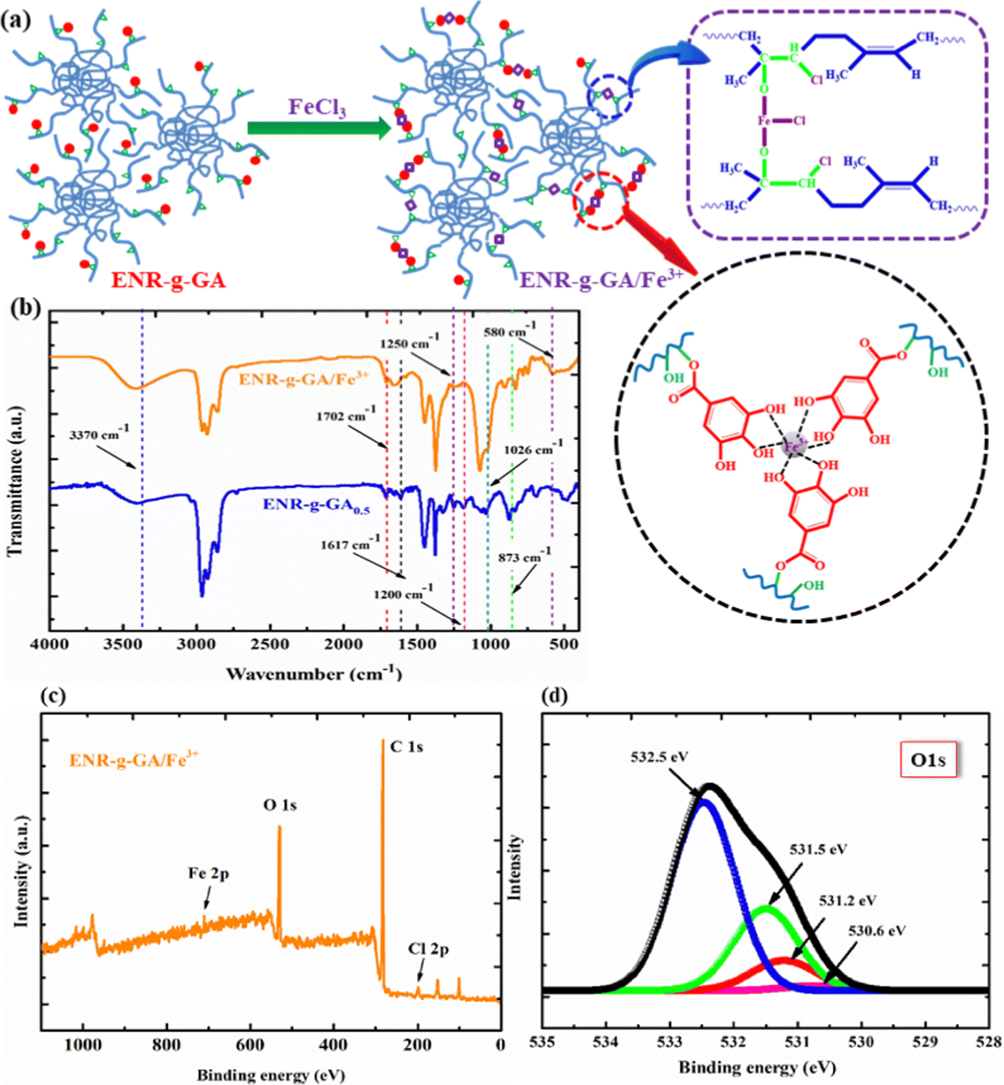 | ||
| Fig. 4 (a) Schematic representation of the crosslink mechanism of ENR-g-GA with Fe3+. (b) The FTIR spectra of ENR-g-GA/Fe3+ and compared with ENR-g-GA0.5. (c) Survey scan of ENR-g-GA/Fe3+, and (d) O 1s spectra of ENR-g-GA/Fe3+. | ||
Mechanical properties
It was observed that the tensile strength of the modified ENR metal–ligand complex was higher than the pristine ENR-50 and FeCl3 complex for all cases. Moreover, the tensile strength augments with increasing FeCl3 content. It was noticed from Fig. 5a that the tensile strength of ENR-g-GA/Fe0.023+, ENR-g-GA/Fe0.053+, ENR-g-GA/Fe0.0103+ and ENR-g-GA/Fe0.153+ increases 61.9%, 94%, 248%, and 69.4%, respectively, as compared to the pristine ENR–FeCl3 complex with their corresponding FeCl3 content (see Table S3 and Fig. S5 for further details, ESI†). The tensile strength of the modified ENR–metal complex was increased from 4.42 MPa to 19.6 MPa with an increase in the FeCl3 from 0.02 to 0.10; then, the increment decreased a little to 14.8 MPa for the FeCl3 content of 0.15. Higher FeCl3 content made the GA-modified ENR brittle due to high crosslinking. This was due to forming a metal–ligand (phenolic OH) coordination bond with Fe3+ in addition to the epoxy–Fe3+ coordination bond. Elongation at break of ENR-g-GA/Fe also decreased from 667% to 12%, increasing the FeCl3 content from 0.02 to 0.15. | ||
| Fig. 5 (a) Tensile strength of ENR/Fe and ENR-g-GA/Fe for Fe3+ 0.02, 0.05, 0.10 and 0.15. (b) The crosslink density of the pristine ENR/Fe complex and ENR-g-GA/Fe complex with varying FeCl3 content (0.02, 0.05, 0.10, 0.15). (c) Tensile strength of ENR-g-GA/Fe with different Fe3+ content and their corresponding self-healing. | ||
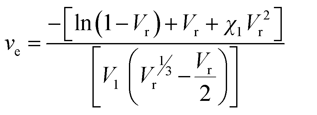
The crosslink density of the crosslinked pristine ENR-50 and the crosslinked ENR-g-GA was determined by a swelling method. The crosslinked density was calculated using the Flory–Rehner equation and is presented in Fig. 5b. The result is in the same trend as the mechanical property, i.e., the crosslink density of crosslinked ENR-g-GA increased from 2.45 × 10⁻⁴ to 3.59 × 10⁻⁴ mol cm−3 with an increasing amount of FeCl3. This was due to the Fe3+ ion-assisted crosslinking with the phenolic OH and the epoxy groups. This similar trend was also followed for the pristine ENR–FeCl3 complex, but the values were less compared to the GA-modified ENR as expected (1.75 × 10⁻⁴ to 2.9 × 10⁻⁴ mol cm−3). The observations made in crosslink density are in line with the findings of mechanical properties.
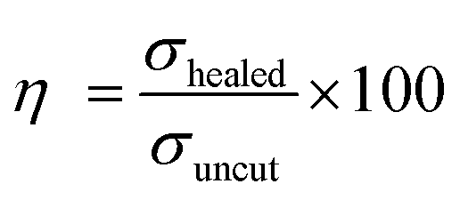
To understand the self-healing ability of the sample, each dumble-shaped sample was cut into two parts and then rejoined. The sample was kept in an oven at 100 °C for 1 hour, and then the sample was taken out and kept at room temperature, following which the physico-mechanical testing was carried out after 24 hours. The strength of the self-healed product of the crosslinked ENR-g-GA with varying FeCl3 content is shown in Fig. 5c. The result of the self-healing efficiency is represented in Table S4 (ESI†). The tensile strength of a healed sample of ENR-g-GA/Fe0.023+ was 1.99 MPa and the elongation at break was 323%, which is almost 42.9% efficiency in tensile strength and 48.4% efficiency in elongation at break compared to the corresponding uncut sample. During the conditioning period, the phenolic OH of GA and the epoxy group present at the damaged surface recombined with the Fe3+ ion. From this result, it was also observed that the efficiency of the tensile strength of the material decreased from 42.9% to 6.7% and the efficiency of elongation at break from 48.4% to 35% with increasing FeCl3 content from 0.02 to 0.10. This was due to the increasing crosslinking density, which forms a more crosslinked rigid network and decreases the possibility of the molecule flowing across the cut interface required for healing.
Dynamic mechanical analysis
The temperature sweep study in DMA analysis conveys the understanding of the molecular motion of the polymeric material at different temperatures. Fig. 6(a and b) demonstrates the loss factor (tanδ) and log storage modulus (LogE′) as a function of temperature for the modified ENR–FeCl3 complex with varying FeCl3 content as compared with the pristine ENR–FeCl3 complex with FeCl3 of 0.10. The height of tan δ was found to be decreased with increasing FeCl3 content, which may be due to the increasing crosslink density of the modified material. The higher crosslink density restricts the molecular motion by increasing the 3D network structure within the polymer by forming ligand–Fe3+coordination bonds. Additionally, the tanδ curve unveils information about the Tg of the material. It was also observed from Fig. 6a that the Tg shifted towards higher temperatures with increasing crosslink density, i.e., with increasing FeCl3 content. The Tg of the ENR/Fe0.103+, ENR-g-GA/Fe0.023+, ENR-g-GA/Fe0.053+, and ENR-g-GA/Fe0.0153+ was obtained at −4.5 °C, 11.7 °C, 14.9 °C, and 20.8 °C, respectively (Table S5, ESI†). The higher crosslink density reduced the molecular chain's flexibility, resulting in increased glass transition temperature. The storage modulus of the GA-modified ENR–FeCl3 complex was higher than that of the pristine ENR–FeCl3 complex. Moreover, the values at the transition region were found to be increased with increasing FeCl3 content due to the increasing stiffness.
 | ||
| Fig. 6 Tanδ (a) and log storage modulus (b) vs. temperature for ENR and the modified ENR–FeCl3 complex. LogE′, E′′ vs. log frequency of ENR/Fe0.103+ (c), ENR-g-GA/Fe0.053+ (d), ENR-g-GA/Fe0.103+ (e) and ENR-g-GA/Fe0.153+(f). | ||
The frequency sweep of the GA-modified ENR–FeCl3 complex with different FeCl3 content was studied and compared with the pristine ENR–FeCl3 complex (Fig. 6(c–f)). This study provides insight into the viscoelastic property of the pristine ENR–FeCl3 complex and ENR-g-GA complex with FeCl3 by comparing the storage modulus (E′) and loss modulus (E′′) over a frequency range from 0.01 to 100 Hz. Fig. 6(c–f) shows that the storage modulus is higher than the loss modulus, which implies that the polymer is more solid-like. It was also noticed that the storage modulus of the ENR-g-GA complex at any point of time or frequency was higher than that of the pristine ENR complex. Moreover, this value was increased with increasing FeCl3 content. It was also observed that within the above-mentioned frequency range, all samples have crossover points except ENR-g-GA/Fe0.153+ This may be due to the formation of the highest crosslinked structure within the polymer, which makes the polymer stiffer. The modulus value obtained at the crossover point is represented in Table S6 (ESI†). From the table, it was observed that the modulus value at the crossover point was increased with increasing crosslink density.
Conductive composite application
 | ||
| Fig. 7 (a) Schematic representation of preparing the temperature sensor. (b) Voltage–current (VI) characteristics plot, (c) ΔR/R0vs. temperature for the temperature coefficient, (d) ΔR/R0vs. time plot for repeatable temperature sensing properties, (e) fitted curve plot between ln(R) and 1000/T (K), and (f) ln(σ) has vs. T−(1/4). | ||
Furthermore, for the CNT-filled system, the distributed carbon nanotubes act as resistors, and the elastomer provides a flexible and strong matrix to hold the fillers. Such a system ought to showcase temperature-sensing behavior due to the carbon nanotube's inherent temperature dependence of resistance. Thermistors showcase significant changes in electrical resistance on the application of temperature stimuli. These are thermally sensitive resistances that can have a negative or positive temperature coefficient of resistance, i.e., on the application of temperature, there is either a decrease or an increase in the resistance value. In such a scenario, the impact of the elastomer's inherent thermal expansion has a marginal role in impacting the temperature-sensing behavior.62
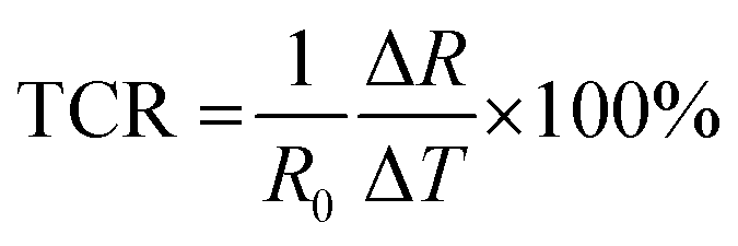
The temperature was swiped from 30 °C to 50 °C on a heating stage at a 5 °C min−1 heating rate. It was observed that there was a decrease in resistance value from 4.46 × 10³ Ω to 4.3 × 10³ Ω, as shown in Fig. S7a (ESI†), suggesting the prominent negative temperature of coefficient (NTC) behavior of carbon nanotubes. The temperature coefficient of resistance (TCR) was calculated using eqn (5):
 | (5) |
The temperature coefficient of resistance of the developed sensors was found to be −0.17% °C−1, as shown in Fig. 7c. However, apart from the TCR, the sensor's ability to hit back to its original value after removing temperature stimuli is crucial. Therefore, the cycling stability of the developed sensors was also investigated. The temperature was swiped from 30 °C to 50 °C and back to 30 °C for five consecutive cycles. It was noted that the sensor demonstrated repeatable temperature sensing properties, as depicted in Fig. 7d. The thermal index is another major factor of scrutiny that plays a crucial role in the thermistor's performance. It demonstrates a sensor's sensitivity and is closely related to the activation energy of the material. The thermal index was calculated as per the following eqn (6):
 | (6) |
The slope of the fitted curve plotted between ln(R) and 1000/T (K) provides information about the thermal index, which is 781.2 K in this case, as shown in Fig. 7e. The probing of the underlying sensing mechanism of the polymer and the change in conductivity of the polymer nanocomposite on the application of temperature has been studied. Based on previous reports,1,2 a variable range hopping mechanism was anticipated to contribute towards the sensing behavior of the developed sensing films. To confirm the above mechanism, ln(σ) was plotted against the T−(1/4), as shown in Fig. 7f. The curve showcased a linear fit with a corresponding R2 value of 0.99, suggesting that the underlying conduction mechanism has been variable range hopping. Moreover, to visually monitor the sensor's response to temperature stimuli, the sensor was attached to the outside of a polyethylene terephthalate cup, as shown in Fig. S7(b–d) (ESI†). The corresponding thermal image is shown in Fig. S7b (ESI†). Hot water at 50 °C was added to the cup, as shown in Fig. S7c (ESI†). It was observed that after 12 seconds, the sensor came to an equilibrium with the inside temperature of the water, as shown in Fig. S7d (ESI†), visually confirming the temperature sensing response of the developed sensing device. The average response time observed has been 1.66 s °C−1.
 | ||
| Fig. 8 Tensile strength and self-healed tensile strength of the CNT-filled ENR-g-GA/Fe with different CNT loadings. | ||
Conclusions
In this study, we successfully modified ENR-50 by grafting GA onto the polymer. Using a facile, cost-effective, low-temperature process, we crosslinked the modified ENR with FeCl3via a metal–ligand coordination bond. The successful modification of ENR-50 and the formation of crosslinks with Fe3+ ions was characterized by FTIR, UV, and XPS. The result indicated 20.92% grafting of ENR with GA. The impact of the modification and the crosslinking with Fe3+ ions was established with the mechanical property, which indicated almost 63%, 225%, 284%, and 74% increment of tensile strength with increasing FeCl3 content from 0.02 to 0.15 as compared to the corresponding pristine ENR–FeCl3 complex.Moreover, the formation of successful metal–ligand coordination of the modified material was measured by using the Flory–Rehner equation, which indicated a higher crosslink density of 2.45 × 10⁻⁴ to 3.59 × 10⁻⁴ mol cm−3 with an increasing amount of FeCl3 as compared with the pristine ENR. DMA evaluated the viscoelastic property of the crosslink-modified material under frequency sweep and temperature sweep mode. All these experiments supported our proposed crosslink mechanism between the phenolic OH of grafted GA on ENR with an Fe3+ ion, oxirane group, and Fe3+. Furthermore, we dispersed CNTs in the modified ENR using a solution mixing process and printed a temperature sensor following a solution casting method. Both the unfilled and the CNT-filled film exhibited self-healing capacity. The result showed a 42.9% recovery in tensile strength for ENR-g-GA/Fe0.023+ and 31.2% recovery in tensile strength of the CNT-filled film with a CNT content of 2%. The CNT-filled cast film showed a resistance value of 4460 Ω at a constant current of 4.5 mA at 2% filler loading. This confirmed the conductor-like behavior indicated by a linear voltage–current relationship. The sensor showed a decreasing resistance value of 4460 Ω to 4300 Ω with a temperature coefficient value of −0.17% °C−1 within a temperature range from 30 °C to 50 °C.
In summary, we have successfully established a high-strength, self-healable, sustainable elastomeric highly sensitive, repeatable temperature sensor and conductor via metal–ligand coordination following a straightforward and cost-effective method.
Author contributions
Aparna Guchait: experimentation, data interpretation, and writing the original draft. Simran Sharma: conducting conductivity testing and temperature sensing, data interpretation and writing the original draft. Santanu Chattopadhyay: supervision, and reviewing. Titash Mondal: conceiving the idea, supervision, reviewing and writing, and editing the original draft.Conflicts of interest
There are no conflicts to declare.Acknowledgements
AG acknowledges the IIT Kharagpur for funding her scholarship. SS acknowledges SERB for her fellowship and TM also acknowledges SERB for providing funds to develop sensor testing facilities vide file number (Science and Engineering Research Board (SERB), India, through project no. EEQ/2020/000139).References
- M. Selvan T, S. Sharma, S. Naskar, S. Mondal, M. Kaushal and T. Mondal, ACS Appl. Mater. Interfaces, 2022, 14, 45921–45933 CrossRef CAS PubMed.
- S. Sharma, M. Selvan, S. Naskar, S. Mondal, P. Adhya, T. Mukhopadhyay and T. Mondal, ACS Appl. Mater. Interfaces, 2022, 14, 57265–57280 CrossRef CAS PubMed.
- A. Haridas, S. Sharma, K. Naskar and T. Mondal, ACS Appl. Mater. Interfaces, 2023, 15, 17279–17292 CrossRef PubMed.
- https://www.researchandmarkets.com/reports/5744262/flexible-electronics-global-market-report (accessed on 14.07.2023).
- https://www.precedenceresearch.com/flexible-electronics-market (accessed on 14.07.2023).
- https://www.gminsights.com/industry-analysis/temperature-sensor-market (Accessed on 26.08.2023).
- S. Yao, P. Swetha and Y. Zhu, Adv. Healthcare Mater., 2018, 7, 1–27 Search PubMed.
- M. L. Hammock, A. Chortos, B. C. K. Tee, J. B. H. Tok and Z. Bao, Adv. Mater., 2013, 25, 5997–6038 CrossRef CAS PubMed.
- B. Arman Kuzubasoglu and S. Kursun Bahadir, Sens. Actuators, A, 2020, 315, 112282 CrossRef CAS.
- V. K. Rai, Appl. Phys. B: Lasers Opt., 2007, 88, 297–303 CrossRef CAS.
- J. Liu, M. Liu, Y. Bai, J. Zhang, H. Liu and W. Zhu, Sensors, 2020, 20, 1–26 Search PubMed.
- T. O. Boucher, Computer Automation in Manufacturing: An Introduction, Springer Science-Business Media, 2012 Search PubMed.
- H. Prajapati and N. N. Deshmukh, Meas. J. Int. Meas. Confed., 2019, 140, 582–589 CrossRef.
- C. Bali, A. Brandlmaier, A. Ganster, O. Raab, J. Zapf and A. Hübler, Mater. Today Proc., 2016, 3, 739–745 CrossRef.
- S. Khan, L. Lorenzelli and R. S. Dahiya, IEEE Sens. J., 2015, 15, 3164–3185 Search PubMed.
- B. A. Kuzubasoglu, E. Sayar and S. K. Bahadir, IEEE Sens. J., 2021, 21, 13090–13097 CAS.
- S. Y. Hong, Y. H. Lee, H. Park, S. W. Jin, Y. R. Jeong, J. Yun, I. You, G. Zi and J. S. Ha, Adv. Mater., 2016, 28, 930–935 CrossRef CAS PubMed.
- S. K. Mahadeva, S. Yun and J. Kim, Sens. Actuators, A, 2011, 165, 194–199 CrossRef CAS.
- T. Q. Trung and N. E. Lee, Adv. Mater., 2016, 28, 4338–4372 CrossRef CAS PubMed.
- X. Peng, X. Zhang, R. Wang, Y. Chen, X. Chu, L. Kong, X. Yan and M. Kuang, ACS Appl. Electron. Mater., 2022, 4, 1949–1957 CrossRef CAS.
- K. S. Karimov, M. T. S. Chani and F. A. Khalid, Phys. E, 2011, 43, 1701–1703 CrossRef CAS.
- A. Nag, R. B. V. B. Simorangkir, D. R. Gawade, S. Nuthalapati, J. L. Buckley, B. O’Flynn, M. E. Altinsoy and S. C. Mukhopadhyay, Mater. Des., 2022, 221, 110971 CrossRef CAS.
- B. Davaji, H. D. Cho, M. Malakoutian, J. K. Lee, G. Panin, T. W. Kang and C. H. Lee, Sci. Rep., 2017, 7, 1–10 CrossRef CAS PubMed.
- M. Soni, M. Bhattacharjee, M. Ntagios and R. Dahiya, IEEE Sens. J., 2020, 20, 7525–7531 CAS.
- W. P. Shih, L. C. Tsao, C. W. Lee, M. Y. Cheng, C. Chang, Y. J. Yang and K. C. Fan, Sensors, 2010, 10, 3597–3610 CrossRef CAS PubMed.
- J. Hu, J. Yu, Y. Li, X. Liao, X. Yan and L. Li, Nanomaterials, 2020, 10, 664 CrossRef CAS PubMed.
- L. Li, X. Fu, S. Chen, S. Uzun, A. S. Levitt, C. E. Shuck, W. Han and Y. Gogotsi, ACS Appl. Mater. Interfaces, 2020, 12, 15362–15369 CrossRef CAS PubMed.
- D. Sengupta, J. Romano and A. G. P. Kottapalli, npj Flex. Electron., 2021, 5, 1–14 CrossRef.
- S. Khan and L. Lorenzelli, Smart Mater. Struct., 2017, 26, 083001 CrossRef.
- R. Liu, L. He, M. Cao, Z. Sun, R. Zhu and Y. Li, Front. Chem., 2021, 9, 1–15 Search PubMed.
- M. Lin, Z. Zheng, L. Yang, M. Luo, L. Fu, B. Lin and C. Xu, Adv. Mater., 2022, 34, 2107309 CrossRef CAS PubMed.
- G. Ziyatdinova, E. Kozlova and H. Budnikov, J. Electroanal. Chem., 2018, 821, 73–81 CrossRef CAS.
- S. Samanta, V. K. Rangasami, N. A. Murugan, V. S. Parihar, O. P. Varghese and O. P. Oommen, Polym. Chem., 2021, 12, 2987–2991 RSC.
- S. Samanta, V. K. Rangasami, H. Sarlus, J. R. K. Samal, A. D. Evans, V. S. Parihar, O. P. Varghese, R. A. Harris and O. P. Oommen, Acta Biomater., 2022, 142, 36–48 CrossRef CAS PubMed.
- A. Guchait, D. Ganguly, C. Sengupta, S. Chattopadhyay and T. Mondal, ACS Sustainable Chem. Eng., 2022, 10, 16780–16792 CrossRef CAS.
- R. Hamzah, M. A. Bakar, O. S. Dahham, N. N. Zulkepli and S. S. Dahham, J. Appl. Polym. Sci., 2016, 133, 44123 CrossRef.
- S. Bhattacharjee, A. K. Bhowmick and B. N. Avasthi, Polymer, 1993, 34, 5168–5173 CrossRef CAS.
- S. Sathornluck and C. Choochottiros, J. Appl. Polym. Sci., 2019, 136, 48267 CrossRef.
- O. S. Dahham, N. Z. Noriman, R. Hamzah, T. Adam, Z. Shayfull, S. Sudin and S. Z. Syed Idrus, J. Phys. Conf. Ser., 2018, 1019, 012054 CrossRef.
- R. Whba, M. Sukor, L. T. Khoon, S. Ibrahim and N. S. Mohamed, Polymers, 2021, 13, 660 CrossRef CAS PubMed.
- J. Jeerupun, J. Wootthikanokkhan and P. Phinyocheep, Macromol. Symp., 2004, 216, 281–292 CrossRef CAS.
- R. H. M. Mas Haris and G. Raju, Exp. Polym. Lett., 2014, 8, 85–94 CrossRef.
- B. Roshan and S. Ravindranath, J. Drug Delivery Ther., 2019, 9, 661–668 CAS.
- A. R. Khaskheli, S. Naz, F. Ozul, A. Aljabour, S. A. Mahesar, I. H. Patir and M. Ersoz, Adv. Mater. Lett., 2016, 7, 748–753 CrossRef CAS.
- W. Wang, Q. Chen, C. Jiang, D. Yang, X. Liu and S. Xu, Colloids Surf., A, 2007, 301, 73–79 CrossRef CAS.
- F. Harun and C. H. Chan, Polymer Compos. Mater., 2016, 37–59 Search PubMed.
- C. Zhang, Y. Bai, W. Liu and B. Cheng, Int. J. Adhes. Adhes., 2019, 90, 126–131 CrossRef CAS.
- L. Wang, X. Zhang, K. Yang, Y. V. Fu, T. Xu, S. Li, D. Zhang, L. N. Wang and C. S. Lee, Adv. Funct. Mater., 2020, 30, 1904156 CrossRef CAS.
- M. S. Masoud, A. E. Ali, S. S. Haggag and N. M. Nasr, Spectrochim. Acta, Part A, 2014, 120, 505–511 CrossRef CAS PubMed.
- B. Kang, T. P. Vales, B. K. Cho, J. K. Kim and H. J. Kim, Molecules, 2017, 22, 1976 CrossRef PubMed.
- C. Cappelli, B. Mennucci and S. Monti, J. Phys. Chem. A, 2005, 109, 1933–1943 CrossRef CAS PubMed.
- B. Badhani and R. Kakkar, Struct. Chem., 2017, 28, 1789–1802 CrossRef CAS.
- T. Mondal, R. Ashkar, P. Butler, A. K. Bhowmick and R. Krishnamoorti, ACS Macro Lett., 2016, 5, 278–282 CrossRef CAS PubMed.
- R. A. Zangmeister, T. A. Morris and M. J. Tarlov, Langmuir, 2013, 29, 8619–8628 CrossRef CAS PubMed.
- L. Guo, T. Qiang, Y. Ma, L. Ren and C. Zhu, ACS Sustainable Chem. Eng., 2021, 9, 8393–8401 CrossRef CAS.
- M. Mukaddam, Y. Wang and I. Pinnau, ACS Omega, 2018, 3, 7474–7482 CrossRef CAS PubMed.
- F. Luzi, D. Puglia, F. Dominici, E. Fortunati, G. Giovanale, G. M. Balestra and L. Torre, Polym. Degrad. Stab., 2018, 152, 162–176 CrossRef CAS.
- J. Hernández-Fernández, E. Rayón, J. López and M. P. Arrieta, Macromol. Mater. Eng., 2019, 304, 1900379 CrossRef.
- C. M. Yang, K. Chathuranga, J. S. Lee and W. H. Park, Polym. Test., 2022, 116, 0–9 Search PubMed.
- K. Damampai, S. Pichaiyut, S. Mandal, S. Wießner, A. Das and C. Nakason, Polymers, 2021, 13, 4145 CrossRef CAS PubMed.
- S. Mandal, F. Simon, S. S. Banerjee, L. B. Tunnicliffe, C. Nakason, C. Das, M. Das, K. Naskar, S. Wiessner, G. Heinrich and A. Das, ACS Appl. Polym. Mater., 2021, 3, 1190–1202 CrossRef CAS.
- Q. Li, L. Zhang, X. Tao and X. Ding, Adv. Healthcare Mater., 2017, 6, 2017 Search PubMed.
Footnote |
| † Electronic supplementary information (ESI) available. See DOI: https://doi.org/10.1039/d3sm01367g |
| This journal is © The Royal Society of Chemistry 2024 |