 Open Access Article
Creative Commons Attribution 3.0 Unported Licence
CO2 assisted geo-polymerization: a win-win pragmatic approach for the synthesis of soda ash leading to reversal of the climate clock†
Sandeep
Gupta
 *ab
*ab
aResearch and Development in Construction Chemicals, CO2 & Waste Utilized Building Materials/Nanomaterials, Room No. 226/228, Building Materials and Environmental Sustainability Division, CSIR-Central Building Research Institute, Ministry of Science & Technology, Govt. of India, Roorkee 247667, Uttarakhand, India. E-mail: sandeep@cbri.res.in; sdg.chem@gmail.com; Tel: +91-8853080464
bAcademy of Scientific and Innovative Research (AcSIR), Ghaziabad 201002, India
First published on 5th November 2024
Abstract
It is surprising to note that there are very few literature reports available that envisage CO2 utilization with sodium silicates. Our research extends this concept by integrating CO2 assisted utilization of fly ash with sodium silicate. The alumino-silicate polymeric material was characterized using FT-IR and NMR techniques confirming the presence of Si–O–Al and Si–O–Si linkages, which are the foundations of the hardened structure, contributing to the strength in the block. Chemical tests and spectroscopic measurements further confirmed the phase and crystallinity of the synthesized soda ash. A feasible reaction mechanism has also been proposed for the alumino-silicate polymerization, which not only leads to the formation of industrially important chemicals like Na2CO3 (soda ash) but also results in the making of construction blocks with strengths of 11–14 MPa and water absorption of 11–15%. The presented chemical scheme utilizes a voluminous amount of CO2, thereby this approach may conserve the global carbon budget, and hence it may play an important role in reversing the climate clock.
Sustainability spotlightIntegrating CO2 and fly ash valorisation with sodium silicate in the making of non-fired alumino-silicate green blocks without cement and NaOH, along with soda ash. The presented scheme supports the circular economy, construction technology development and a waste to wealth approach which are in accordance with the UN SDGs 9.5, 9.7, 11.A, 11.6, 12.4, 12.5 and 13. |
1 Introduction
Carbon dioxide utilization has been extensively studied to mitigate the greenhouse effect and for production of value added raw chemicals, such as formic acid, urea, salicylic acid, carbamates, methanol, methane, production of fuels, CO + H2 syn gas, enhanced oil recovery, geological sequestration, mineralization of CO2 in the form of carbonate for building material applications etc., over the past few decades.1–3 Valorization of carbon dioxide offers twin advantages, firstly mitigating climate change and secondly manufacturing of economically feasible products for mankind.4 Carbon capture utilization and sequestration (CCUS) means capturing CO2 from industrial point sources such as thermal power plants, cement and metallurgical industries and preventing it from entering into the atmosphere, either by storing it or utilizing it.5 Emission of CO2 cannot be controlled with the increase in the growth of industries and other anthropogenic activity by humans, therefore the present approach is to use more and more CO2 utilized value added products.6 If we would be able to use significant volumes of CO2 in the construction sector, then it may lead to a substantial reduction in the overall carbon footprint since enormous amounts of CO2 emissions are coming out from industries.7 The concept of the carbon budget is based on an almost linear relationship between the cumulative emissions and the temperature rise.5,8 The climate clock visualizes how much CO2 can still be released into the atmosphere before the world exceeds the critical thresholds of 1.5 °C and 2.0 °C of global warming. To stay below the 1.5 °C threshold, the remaining carbon budget is 235 Gt, which is projected to be exhausted in approximately 5.5 years. Similarly, to stay below the 2.0 °C threshold, the carbon budget is 985 Gt, which is expected to be exhausted in around 23.5 years, based on current emission rates.9,10 This carbon budget answers the question, how much carbon dioxide can be emitted globally before we reach 1.5 °C above pre-industrial levels. It also indicates how quickly the Earth is approaching 1.5 °C of global warming and displays the CO2 emissions that have already been released into the atmosphere.11 Experts warn that once the 1.5 °C mark is crossed then many of the harmful effects of climate change would become irreversible with long-lasting consequences for humankind as well as the planet.12Geo-polymers include a well-built three dimensional network of alumino-silicate cross linking structures which is synthesized by the use of strong alkali sodium hydroxide (10–14 M) activation and sodium silicate.13,14 The silicate and aluminate network provides tremendous durability to geo-polymers with excellent strength and mechanical characteristics.15 Handling of such harsh alkali solution for field labour is the major concern of widespread applications of geo-polymer technology.16 Moreover, it is essential to look forward to alternate synthetic schemes for the synthesis of alumino-silicate materials that do not utilize a harsh alkali like the NaOH activator which will create significant problems in handling because of the corrosiveness.17 The CO2 utilization scheme especially mineral carbonation (CaO + CO2 = CaCO3) approach is too slow and alkali activated geo-polymerization utilizes very harsh reagents like NaOH.18 Ash wastes, which are currently abundant, create significant challenges when it comes to disposal. They cannot be utilized alone in landfill or soil stabilization processes which can adversely affect soil fertility. Building materials are much more voluminous thereby utilizing more CO2 as compared to other CO2 utilization areas. Hence, the aforementioned concern is addressed in this scheme for the utilization of CO2 integrated with fly ash and sodium silicate. To the best of our knowledge, CO2 assisted valorization of industrial waste like fly ash, agro ash and slag in the manufacturing process of alumino-silicate non-fired green blocks without using cement and NaOH along with the synthesis of industrially important raw chemical soda ash has not been explored to date.
The proposed initiatives align well with several Sustainable Development Goals (SDGs) set by the United Nations, particularly SDG 9.5, 9.7 support domestic technology enlargement, research and innovation for engineering applications in developing countries. SDGs 11 A, 11.6 advocate a waste-to-wealth approach, aiming to reduce environmental impacts in urban areas while promoting sustainable materials. SDGs 12.4, 12.5 focus on recycling and reusing of industrial waste for transforming into value added products.19
2 Experimental section
2.1 Instrumentation
The XRD pattern of the solid powder was characterized using a Rigaku X-ray diffractometer with measurement conditions consisting of continuous scanning in the range of 5°–70° with a scan rate of 2° per minute using copper K alpha radiation, wavelength 0.15 nm. Stretching and vibration bands of the alumino-silicate material were confirmed by FTIR spectroscopy, which was run on a Nicolet 6700 spectrometer (Thermo Scientific) equipped with an iTR module. The compressive strength was measured using cubic samples of dimensions 12.7 cm × 12.7 cm × 12.7 cm on a Heico compressive strength testing machine, which was employed with a 2.9 kN per second load in MPa units. Solid state 27Al MAS NMR and 29Si Magic Angle Spinning Nuclear Magnetic Resonance (MAS NMR) studies of the materials were carried out using an ECX 400 MHz JEOL instrument with a standard probe 4 mm broad band along with 4 mm ZrO2 rotor. Operating conditions for 29Si NMR included 11![[thin space (1/6-em)]](https://www.rsc.org/images/entities/char_2009.gif) 000 scans, relaxation delay 5 seconds, pulse rate at 45° and for 27Al NMR the operating conditions included 3000 scans and a relaxation delay of 4 seconds with a pulse rate at 45°.
000 scans, relaxation delay 5 seconds, pulse rate at 45° and for 27Al NMR the operating conditions included 3000 scans and a relaxation delay of 4 seconds with a pulse rate at 45°.
2.2 Materials and methods
Fly ash collected from the thermal power plant was analyzed using X-ray fluorescence spectroscopy to check the optimum content of amorphous silica, alumina and calcium oxide, and thereafter it was screened through a particular sieve before being used. The detailed methodology schematic is illustrated in Fig. 1.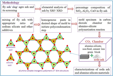 | ||
| Fig. 1 Flow sheet diagram for CO2 assisted utilization of fly ash catalyzed by sodium silicate for the creation of a 3-dimensional alumino-silicate network in a block. | ||
Sodium silicate containing SiO2 30%, Na2O 9.4%, viscosity 0.40 Pa s, specific gravity 1.43 g cm−3 was used to make the fly ash paste along with glycerol as a plasticizing agent and it was diluted further with water as per requirement (ESI, Scheme 1 S1†). Specimens were carbonated with different carbonation curing regimes up to 12 h by applying CO2 gas as 10% CO2 gas under ambient pressure and temperature.
3 Results and discussion
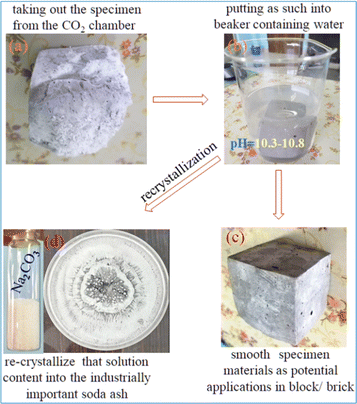
The carbonation reaction is very slow due to the low diffusion rate of CO2 into the source materials because CO2 is a thermodynamically stable molecule containing 2σ and 2π bonds, on the other hand sodium silicate has ionic bonds with an excellent tendency for its ions to gain or lose electrons in the reaction. In addition to favourable liquid–gas contact, sodium silicate concentration and pH can also affect the growth of silica from the silicate solution. To implement this concept, a two-step mixing approach is used, as shown in Fig. 1; the first step is the rigorous mixing of the solution of sodium silicate with fly ash containing reactive silica and alumina. In the second step, carbon dioxide is injected into the mold with the desired shape that contains all the ingredients.Thereafter, the fly ash paste in the mold is allowed to undergo the chemical reaction for hardening (8–12 h) at room temperature and ambient pressure without introducing additional complexities, making the process more practical at the proof of concept stage. As the reaction proceeds with respect to time, CO2 diffuses into the silicate solution through the fly ash paste, and it forms the silicic acid which is a highly unstable molecule (Fig. 2) that further decomposes into unstable silicon dioxide20 as shown in Fig. 2. Furthermore, SiO2 is an unstable molecule and reorganises the bonds with Al2O3, as we know silicon has a vacant d orbital so it forms pπ–dπ back bonding21 over the entire 3 dim network (electron donated from the filled orbital of the O atom to the unfilled orbital of the Si atom) thereby enhancing the strength and hardening of the alumino-silicate materials.22 This process involves the reorganization and polymerization of silica and alumina, which are derived from fly ash. The paste of fly ash with sodium silicate is catalyzed by CO2, facilitating the poly-condensation23 process, forming a hardened network as depicted in Fig. 2. It was observed that during the carbonation process, white powder was deposited on the surface of the specimen block (Fig. 3a) and the powder was identified as sodium carbonate,24 an industrially important raw chemical, further demonstrating another perspective of the scheme. To characterize the white powder, it was dissolved in water (Fig. 3b). This dissolution confirms the presence of a highly soluble compound and after recrystallization white crystals of soda ash were obtained (Fig. 3d), along with the block (Fig. 3c). Soda ash produced by this CO2 utilization approach might have some contamination and impurities, therefore it would be suitable for applications where high purity is not a concern. To confirm the characteristics of the white crystalline powder obtained from this process as sodium carbonate, an aqueous solution of soda ash was prepared and the carbon dioxide signal (in ppm) was measured using a CO2 detector as illustrated in Fig. 4a.
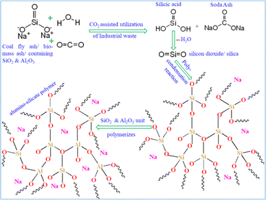 | ||
| Fig. 2 Proposed mechanism for alumino-silicate network creation through CO2 catalyzed fly ash paste with sodium silicate and synthetic scheme for the byproduct soda ash. | ||
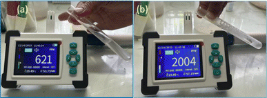 | ||
| Fig. 4 (a) Test tube containing aqueous solution of the soda ash synthesized. (b) Test tube containing acidified solution of the soda ash. | ||
A few drops of dilute hydrochloric acid were added into the test tube containing an aqueous solution of the white powder and effervescence was observed at the mouth of the test tube, as shown in Fig. 4b. This reaction caused a sudden rise in CO2 concentration, which was also detected by the CO2 detector (Fig. 4b), further confirming the white powder as sodium carbonate.
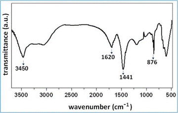
The FT-IR spectrum of sodium carbonate displays notable peaks indicative of its molecular characteristics. A strong peak is observed at 1441 cm−1, along with another peak at 1620 cm−1, both corresponding to the C–O asymmetric stretching vibration25,26 as shown in Fig. 5. Additionally, IR bands at 3450 cm−1 and 1620 cm−1 are attributed to the stretching and bending modes of the –OH groups associated with water. Furthermore, the peak at 876 cm−1 is attributed to the out of plane stretching mode of the CO32− group25,26 and the spectral features collectively confirm the characteristic signature of sodium carbonate.
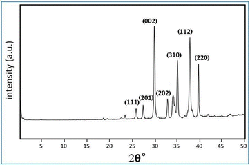
XRD analysis of the sodium carbonate crystals indicated distinct signature peaks at specific Bragg’s 2θ values, as illustrated in Fig. 6. The prominent peaks observed at 26.0°, 27.4°, 30.0°, 34.3°, 37.8°, and 40.0° were indexed to the respective planes (111), (201), (002), (310), (112), and (220). These findings are consistent with the standard JCPDS card number 37-0451 for sodium carbonate, confirming the crystalline nature and phase purity of the synthesized sodium carbonate.27
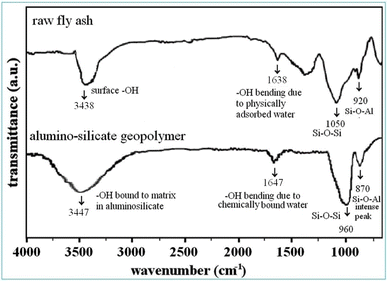
Returning to the discussion of the other synthesized materials, i.e. silica and alumina derived from fly ash and sodium silicate catalyzed by CO2, forming a geo-polymeric alumino-silicate network, which imparts the strength in the block. This segment particularly focuses on the IR spectral bands where silica and alumina species are observed, and is crucial for our research findings. The main band of fly ash appeared between 900–1070 cm−1 due to free silica which is significantly shifted to a lower wavenumber after geo-polymerisation17 as we can see in Fig. 7.
The O–H stretching peak in raw fly ash was observed at 3438 cm−1, indicating the presence of weaker surface hydroxyl groups in raw fly ash. In the geo-polymer the –OH peak appeared at 3447 cm−1, indicating stronger absorption due to the formation of new hydroxyl groups, typically in a more structured environment like water bound to the alumino-silicate geo-polymer matrix.28,29 The O–H bending peak at 1638 cm−1 is usually attributed to the presence of physically adsorbed water on the surface of the fly ash particles. While in alumino-silicate materials the O–H bending peak at 1647 cm−1 is observed, which indicates that a significant portion of the free water present in the raw fly ash has been chemically incorporated into the geo-polymer matrix during the alumino-silicate polymerization process.28,30 In fly ash the sharp peak at 1050 cm−1 corresponds to Si–O–Si stretching vibrations from unreacted or free silica present in the fly ash. A smaller peak at 920 cm−1 represents Al–O–Si stretching in fly ash. In the case of the geo-polymer, the Si–O–Si peak has shifted to around 960 cm−1 indicating the formation of a three-dimensional alumino-silicate network and the Al–O–Si peak observed at 870 cm−1 becomes more prominent, which reflects the increased incorporation of alumina into the silicate network.17,29,30
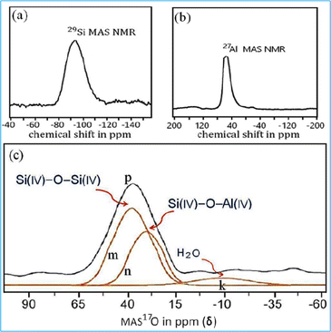
Phase evolution and micro-structural development of this material was examined using advanced characterization techniques, including magic angle spinning NMR spectroscopy probing 29Si and 27Al. The MAS NMR spectra appeared broad, requiring deconvolution of the individual peaks using a Lorentz function and non-linear curve fitting techniques.31 In this article, we focus primarily on demonstrating the linkages and interactions between silica and alumina within the material matrix and hence do not go into much more detail on the simulation, computational analysis and relative area of peaks.
In 29Si MAS-NMR, the chemical shift (δ) is determined by the local environment of the 29Si nuclei, which is influenced by the structural surroundings, particularly the coordination of silicon atoms with oxygen atom. The shift also depends on the degree of condensation of Si–O–Si and Si–O–Al linkages.28 In the 29Si NMR spectrum (Fig. 8a), the signal of the alumino-silicate material was detected at −87 ppm which is attributed to the formation of the silicate linkage32 in the material. The 27Al MAS NMR spectrum of the alumino-silicate polymer exhibited a single characteristic peak with a chemical shift of 56 ppm (Fig. 8b), which corresponds to the tetrahedral coordination33 of Al(IV). For the geo-polymeric structure, 17O MAS NMR is believed to be a key technique for analyzing the amorphous structural linkage as a function of chemical shift (δ) which is based upon the surrounding environment of the 17O nucleus. The 17O MAS NMR spectrum was employed to identify the characteristic signatures of the Si–O–Si and Si–O–Al linkages in the alumino-silicate materials. The characteristic resonance at 38.0 ppm (m peak) was attributed to Si(IV)–O–Si(IV) association,34 indicating the oxygen is linked with silicon atoms within the polymer matrix. The chemical shift (δ) at 29.7 ppm (n peak) revealed the oxygen environment with a Si(IV)–O–Al(IV) association35 and it is a characteristic feature of alumino-silicate networks, where aluminium is substituted in the silicate structure. The chemical shift (δ) at −9.8 ppm (k peak) was attributed to non-bridging oxygen being present which is typically linked with Al–OH and Si–OH positions as well as firmly bound to H2O molecules within the alumino-silicate network as depicted in Fig. 8c. These non-bridging oxygen atoms can affect the properties of the material, particularly in terms of its rigidity and porosity.36
The compressive strength of the synthesized block (dimensions 12.7 cm × 12.7 cm × 12.7 cm) was tested and found to be in the range of 11–14 MPa, making the blocks suitable for domestic applications. A significant advantage of this scheme is its ability to replace conventional fired clay bricks and cement based blocks with non-fired alumino-silicate green blocks.37 The future scope of this research work will explore the ways to optimize the silica modulus without significantly increasing costs by utilizing industrial waste sources of silicate. Fired clay bricks often have uneven surfaces, and ash based blocks synthesized using the CO2 utilization approach exhibit uniformity in shape and size on all sides. This uniformity results in a 12–15% reduction in the amount of cement or wall putty needed, for plastering of walls. Every year, carbon dioxide (CO2) emissions continue to rise, significantly increasing the atmospheric carbon budget and voluminous utilization of carbon dioxide with fly ash into value added construction blocks can be win-win scenario, if applied on a larger scale.
4 Conclusion
An innovative and pragmatic approach is demonstrated for CO2 assisted alumino-silicate polymerization of fly ash catalyzed by sodium silicate for development of the industrially important raw chemical sodium carbonate and non-fired alumino-silicate green blocks without using cement and NaOH. Spectroscopic measurements reveal two key structural linkages Si(IV)–O–Al(IV) and Si(IV)–O–Si(IV) formed in the alumino-silicate materials. The key performance indicators of the block include a mechanical strength of 11–14 MPa and water absorption of 11–15% with a smooth surface. However, there are a few challenges to be addressed like fabrication in a special chamber and CO2 gas diffusion into moulds for the complete reaction inside the block structure before scaling up of this scheme from laboratory to market. However, if we can manage to reduce CO2 emissions or effectively utilize carbon dioxide through innovative technologies, the overall carbon footprint can be mitigated and this could help in achieving a balance where CO2 emissions equal CO2 utilization which is crucial for reaching net-zero goals, aligning with global climate targets. The strategies presented in this article address key concerns of waste-to-wealth, promoting a circular economy, and decarbonizing the construction sector, while driving innovation in domestic construction technology.Data availability
The data supporting this article have been included as part of the ESI† and in the main body of the manuscript.Conflicts of interest
The author declares no competing financial interest.Acknowledgements
Sandeep Gupta conveys his gratitude to Director-CSIR Central Building Research Institute for financial support as In-House CSIR CBRI R&D project (partially) OLP-2203 under the waste to wealth scheme. He also gratefully acknowledges the official help received from Dr L. P. Singh and Dr Soumitra Maiti in the Division. We are thankful to Sh Ankit Bohra for manpower work. The author is also grateful to CIFC-IIT (BHU), Varanasi, India, for sample characterizations.Notes and references
- G. Gadikota, Commun. Chem., 2021, 4, 23 CrossRef CAS PubMed.
- N. Li, L. Mo and C. Unluer, J. CO2 Util., 2022, 65, 102237–102256 CrossRef CAS.
- P. Roy, A. K. Mohanty and M. Misra, Environ. Sci.: Adv., 2023, 2, 409–423 CAS.
- A. Mukherjee and S. Chatterjee, Policy Framework and Deployment Mechanism in India, Report, 2022, pp. 1–163 Search PubMed.
- P. G. Levi and J. M. Cullen, Environ. Sci. Technol., 2018, 52, 1725–1734 CrossRef CAS PubMed.
- F. Meng, N. Brandao and J. M. Cullen, Environ. Sci. Technol., 2024, 58, 2716–2727 CrossRef CAS PubMed.
- G. Fackelmann, C. K. Pham, Y. Rodriguez, M. L. Mallory, J. F. Provencher, J. E. Baak and S. Sommer, Nat. Ecol. Evol., 2023, 7, 698–706 CrossRef PubMed.
- X. Liu, X. Wang, G. Licht and S. Licht, J. CO2 Util., 2020, 36, 288–294 CrossRef CAS.
- G. Centi, E. A. Quadrelli and S. Perathoner, Energy Environ. Sci., 2013, 6, 1711–1731 RSC.
- M. Aresta and A. Dibenedetto, Dalton Trans., 2007, 2975–2992 RSC.
- M. Mikkelsen, M. Jorgensen and F. C. Krebs, Energy Environ. Sci., 2010, 3, 43–81 RSC.
- Z. Liu, Z. Deng, S. Davis and P. Ciais, Nat. Rev. Earth Environ., 2023, 4, 205–206 CrossRef PubMed.
- S. Yan, P. He, D. Jia, X. Duan, Z. Yang, S. Wangac and Y. Zhou, RSC Adv., 2017, 7, 13498–13508 RSC.
- Y. Zhang, T. Li, D. Hou, J. Zhang and J. Jiang, Phys. Chem. Chem. Phys., 2018, 20, 18297–18310 RSC.
- J. L. Bell, P. Sarin, P. E. Driemeyer, R. P. Haggerty, P. J. Chupas and W. M. Kriven, J. Mater. Chem., 2008, 18, 5974–5981 RSC.
- T. G. Lombardo, N. Giovambattista and P. G. Debenedetti, Faraday Discuss., 2009, 141, 359–376 RSC.
- G. M. Nasab, F. Golestanifard and K. J. D. MacKenzie, J. Ceram. Sci. Technol., 2014, 5, 185–192 Search PubMed.
- A. Mellado, C. Catalan, N. Bouzon, M. V. Borrachero, J. M. Monzo and J. Paya, RSC Adv., 2014, 4, 23846–23852 RSC.
- K. Arbi, M. Nedeljkovic, Y. Zuo and G. Ye, Ind. Eng. Chem. Res., 2016, 55, 5439–5453 CrossRef CAS.
- R. Rodriguez-Mosqueda and H. Pfeiffer, J. Phys. Chem. C, 2013, 117, 13452–13461 CrossRef CAS.
- V. V. Annenkov, E. N. Danilovtseva, V. A. Palshin, O. N. Verkhozina, S. N. Zelinskiy and U. M. Krishnan, RSC Adv., 2017, 7, 20995–21027 RSC.
- H. Oberhammer and J. E. Boggs, J. Am. Chem. Soc., 1980, 102, 7241–7244 CrossRef.
- N. Janes and E. Oldfield, J. Am. Chem. Soc., 1986, 108, 5743–5752 CrossRef CAS PubMed.
- J. G. Vail, Ind. Eng. Chem., 1935, 27, 888–893 CrossRef CAS.
- B. Feng, Q. M. Feng, Y. P. Lu and H. H. Wang, J. South. Afr. Inst. Min. Metall., 2015, 1239–1242 CrossRef CAS.
- N. Dordevic, M. Vlahovic, S. Mihajlovic, S. Martinovic, N. Vusovic and J. L. Sajic, Sci. Sinter., 2022, 54, 481–494 CrossRef CAS.
- A. Harabor, P. Rotaru and N. A. Harabor, Annals of the University of Craiova, Physics, 2013, 23, 79–88 Search PubMed.
- S. Moukannaa, A. Nazari, A. Bagheri, M. Loutou, J. G. Sanjayan and R. Hakkou, J. Non-Cryst. Solids, 2019, 511, 76–85 CrossRef CAS.
- C. Li, H. Sun and L. Li, Cem. Concr. Res., 2010, 40, 1341–1349 CrossRef CAS.
- J. G. Jang and H. K. Lee, Constr. Build. Mater., 2016, 102, 260–269 CrossRef CAS.
- S. Li, A. Zheng, Y. Su, H. Fang, W. Shen, Z. Yu, L. Chen and F. Deng, Phys. Chem. Chem. Phys., 2010, 12, 3895–3903 RSC.
- S. Greiser, G. J. G. Gluth, P. Sturm and C. Jager, RSC Adv., 2018, 8, 40164–40171 RSC.
- C. J. Heard, L. Grajciar, C. M. Rice, S. M. Pugh, P. Nachtigall, S. E. Ashbrook and R. E. Morris, Nat. Commun., 2019, 10, 4690 CrossRef.
- S. E. Ashbrook, Z. H. Davis, R. E. Morris and C. M. Rice, Chem. Sci., 2021, 12, 5016–5036 RSC.
- P. S. Neuhoff, P. Zhao and J. F. Stebbins, Microporous Mesoporous Mater., 2002, 55, 239–251 CrossRef CAS.
- P. S. Singh, M. Trigg, I. Burgar and T. Bastow, Mater. Sci. Eng., A, 2005, 396, 392–402 CrossRef.
- Y. R. Pei, J. H. Yang, G. Choi and J. H. Choy, RSC Adv., 2020, 10, 6814–6821 RSC.
Footnote |
| † Electronic supplementary information (ESI) available. See DOI: https://doi.org/10.1039/d4su00541d |
| This journal is © The Royal Society of Chemistry 2024 |

