
The benefit of coupling droplet microfluidics and multiphoton optical microscopy to study the crystallization of polymorphic substances: a case study with ortho-aminobenzoic acid†
Hugo
Cercel
a,
Clément
Brandel
 *a,
Romain
Rac
b,
Clément
Pinètre
a,
Charline J. J.
Gerard
a,
Stéphane
Veesler
c,
Nadine
Candoni
c,
Romain
Grossier
c and
Valérie
Dupray
a
*a,
Romain
Rac
b,
Clément
Pinètre
a,
Charline J. J.
Gerard
a,
Stéphane
Veesler
c,
Nadine
Candoni
c,
Romain
Grossier
c and
Valérie
Dupray
a
aSMS, Univ Rouen Normandie, F-76000 Rouen, UR 3233, France. E-mail: clement.brandel@univ-rouen.fr
bIUT d'Evreux, Univ Rouen Normandie, 55 rue Saint Germain, CS40486, 27004 Evreux Cedex, France
cAix-Marseille Université, CINaM (Centre Interdisciplinaire de Nanosciences de Marseille), CNRS, Campus de Luminy, Case 913, F-13288 Marseille Cedex 09, France
First published on 31st March 2025
Abstract
A new crystallization platform coupling droplet-based microfluidics with two photon and second harmonic generation microscopy operating with a femtosecond pulsed wave laser of tunable wavelength is presented. The present paper demonstrates the performance of this set-up by conducting a large number of independent crystallization experiments in small (nL) unstirred reactors. We used ortho-aminobenzoic acid (o-ABA) as a model substance: it is a polymorphic substance known to exhibit concomitant polymorphism. It was possible to rapidly image and discriminate crystals with a centrosymmetric structure from crystals with a non-centrosymmetric structure by using this new coupling system. By conducting thorough crystallization studies, our set up allowed the impact of small volume on the nucleation behavior of o-ABA polymorphs to be investigated and the occurrence of both solvent mediated transformation and solid–solid transition to be evidenced. In particular, we show that small volume favors the nucleation of the most stable crystal form of o-ABA.
Introduction
Crystallization is a powerful purification technique which also permits the physical attributes of the produced crystals to be controlled.1 It is a key step in the manufacture of many technological products, ranging from fine chemicals (e.g. pharmaceutical materials, fertilizers…) to ceramics (e.g. for optical, electronic or magnetic applications), proteins, foods and agrochemical products.2–4 During crystallization, the compound of interest may crystallize into one or more crystal structures, i.e., polymorphs.5 At a given pressure and temperature, only one polymorph is thermodynamically stable, the other polymorphs are metastable. Under kinetic control, crystallization can give rise to metastable polymorphs. These metastable forms will last until their conversion into the stable form, either by solvent-mediated or by solid–solid transitions.6 It is also possible that crystallization gives rise to a mixture of polymorphs, this is the so-called “concomitant polymorphism” phenomenon.7 This situation arises especially when the energy difference between polymorphs is below 0.5 kcal mol−1 and when the experimental conditions lead to similar nucleation rates for each polymorph.7,8Aiming at the production of a single crystalline form, the design of a robust and reproducible process requires a comprehensive understanding of the crystallization behavior of the system and relies on the identification of the critical process parameters. While phase diagrams display the most stable phases as a function of intensive parameters, the formation of metastable polymorphs can only be studied by means of statistical approaches, most often involving screening-based investigations. Among the different screening techniques, the well-known Crystal16™ apparatus (Technobis Crystallization System, Alkmaar, Netherland) has been intensively used for the design of crystallization processes. This temperature-controlled multi-well technique equipped with a turbidimetric probe allows many experiments to be performed at the mL scale and has been used to measure solubilities, evaluate metastable zone widths or determine nucleation rates.9–11
However, in the case of polymorphic systems, this technique cannot discriminate between solid phases which can induce bias in the determination of the process parameters, in particular in the case of concomitant polymorphism. Currently, ex situ characterization techniques (XRD, Raman spectroscopy, etc.…) are commonly used for crystal identification.12 Few high throughput crystallization set-ups with in situ measurements are available. For instance, the Crystalline apparatus improves the design of the Crystal16 allowing in situ Raman spectroscopy and optical microscopy to be performed.13 The MMicroCryGen performs crystallization at the μL scale within disposable microcapillary film strips which can then be implemented in Raman microscopy for in situ analyses.14
Another high-throughput crystallization technique makes use of the droplet-based microfluidics (DM) technology.15,16 A very high number of small volume (μL to nL) supersaturated droplets are generated which can be regarded as identical crystallization reactors. Optical microscopy,17 Raman spectroscopy,18,19 infrared spectroscopy,20 X-ray fluorescence,21 small angle X-ray scattering,22,23 and X-ray diffraction24,25 have been used as in situ techniques for crystal characterization. Even if DM experiments are usually performed in microchips,26 a more versatile and easy-to-implement set-up has been designed by Lambert et al. which is entirely built on HPLC tubing and PEEK junctions.18 Currently, this set-up permits crystallization to be monitored in situ by means of optical microscopy or Raman spectroscopy, but its versatility makes coupling with other analytical tools possible.
To develop a powerful high-throughput crystallization platform, a suitable in situ analytical tool capable of rapid polymorphic discrimination with sufficient spatial and temporal resolution and operating without access to a synchrotron facility must be developed. For this purpose, it is envisaged to couple DM crystallization with multiphoton optical microscopy, a fast-imaging technique which can be sensitive to solid-state organization. In particular, second harmonic generation (SHG, Fig. 1a) is a nonlinear optical effect which permits distinguishing non-centrosymmetric from centrosymmetric crystal structures.27 It is a non-resonant and nonlinear optical phenomenon in which two collinear electromagnetic waves of the same wavelength interact while they propagate through non-centrosymmetric materials. This interaction is characterized by the formation of a new wave with a wavelength halved with reference to the incident light.28 Besides, another nonlinear optical phenomenon is two photon fluorescence (TPF, Fig. 1b). Contrary to SHG, TPF is a resonant phenomenon in which the molecule in the ground state absorbs simultaneously two photons of wavelength λ to be excited to the singlet state. Then, the molecule relaxes to a lower energy level of the excited state (thermal relaxation) before returning to the ground state by emitting a new photon. This mechanism is similar to single photon fluorescence but in TPF, the wavelength of the emitted photon is lower than the excitation wavelength λ.
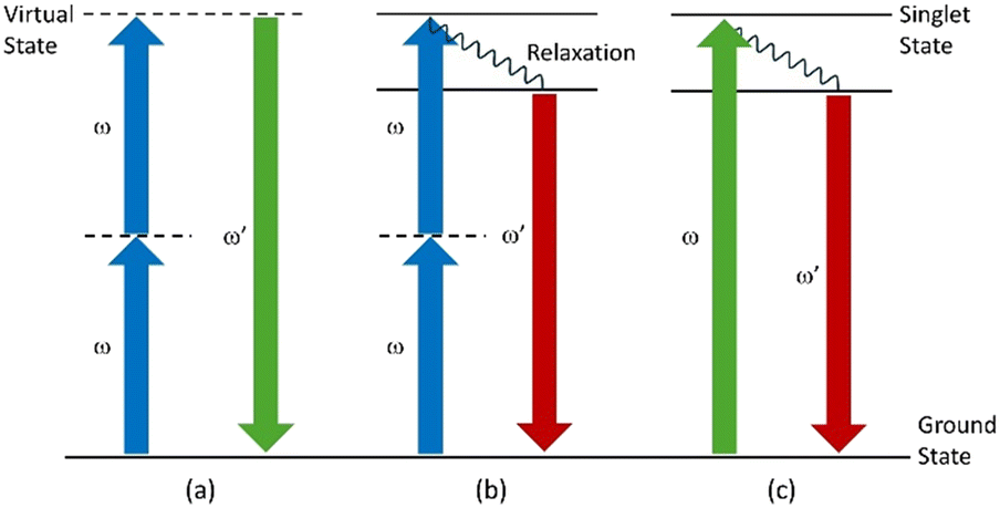 | ||
| Fig. 1 Schematic representation of the different non-linear optical phenomena occurring during multiphoton microscopy in the case of the (a) SHG, (b) TPF or (c) SPF phenomenon. | ||
Multiphoton microscopy offers several advantages. Unlike single photon fluorescence (SPF, Fig. 1c) or Raman scattering, signals are not affected by the fluorescence background and are inherently depth-resolved without the need for a confocal pinhole.29 This gives rise to more intense signals thus reducing the acquisition time.
When coupled to fast rate line scanners, the signals can be used to generate 3D images of crystals with a spatial resolution of ca. 1 μm, within a few seconds.30 SHG and TPF signals can be synchronously collected using dedicated spectrally resolved detectors.31 Thus, as a monitoring technique for a high-throughput crystallization device, multiphoton microscopy exhibits better opportunities than Raman microscopy in terms of acquisition time and spatial resolution. In this context, we propose a new high-throughput crystallization device based on a coupling between DM and multiphoton microscopy.
Anthranilic acid, also called 2-aminobenzoic acid or ortho-aminobenzoic acid (o-ABA), is an important intermediate for the production of several substances in the chemical industry (pharmaceuticals, dyes, cosmetics, etc.). It is a compound exhibiting three different polymorphs, labeled FI, FII and FIII.32–34 FI crystallizes in the non-centrosymmetric space group P21cn and exhibits a SHG signal,35 whereas FII and FIII are centrosymmetric structures (Pbca and P21/c, respectively) and thus could not exhibit any SHG activity. FI crystallizes as block-shaped particles, FII crystallizes as needles or plate-shaped particles and FIII only forms plate-shaped particles. These crystal habits can provide additional information on the differentiation of FI from the others.
FI and FIII are enantiotropically related with a transition temperature of T = 90 °C. FII is monotropically related to the two other forms and could transform into one of them depending on the temperature. As the most metastable form, FII generally appears first during crystallization, in agreement with Ostwald's rule of stages. FII can be kept for months without any detectable transformation into the stable phases if stored, but would transform in less than 1 hour into either FI (if T < 50 °C) or FIII (if T > 50 °C) when stirred as a suspension in a crystallization reactor.36 Using in situ Raman spectroscopy, the crystallization behavior of o-ABA from ethanol/water mixtures has been investigated by Jiang et al.37 They showed that depending on the crystallization conditions, o-ABA could be crystallized into either pure FII, pure FI or as a mixture of both FI and FII (i.e., concomitant polymorphism).
Besides, PAT techniques, including Raman spectroscopy, focused beam reflectance measurements and attenuated total reflectance UV–vis spectroscopy, have also been used to monitor the crystallization of o-ABA and identify polymorphs.38
To illustrate the benefit of coupling DM and SHG/TPF, we herein re-investigate the crystallization behavior of o-ABA, notably using high-throughput and small volume reactors, and explore the polymorphism of this system using multiphoton microscopy as a new in situ analytical tool to monitor crystallization.
Materials and methods
Chemicals and materials
o-Aminobenzoic acid (o-ABA) was purchased from Thermo Scientific (USA) with a chemical purity of 98+% and was used without further purification. HPLC grade ethanol was purchased from VWR (USA). Water was demineralized (2–8 μS cm−1) with an osmosis unit water purification system from OSMOTECH (Buchelay, France). Perfluoropolyether-based oil Krytox GPL106 (η = 822 cSt at 20 °C) was purchased from Chemours (USA) and was used as the continuous phase during microfluidic experiments.Solubility measurements
The solubility of o-ABA, denoted as Csat, was measured in ethanol/water mixtures as a function of temperature by gravimetry and can be calculated using the following equation: Csat = mdry extract/msaturated solution. The temperature was controlled using a thermostat. The data have been computed using the Scilab software.39Droplet microfluidic crystallization set-up
The droplet generation section (Fig. 2, left part) was designed similarly to a published set-up.40 The set-up was stored in a thermostated room set at 20 °C. It is made of two Pico elite plus 11 syringe-pumps (Harvard Apparatus, USA) connected to a HAPC pump controller (Harvard Apparatus, USA), enabling fluids to be pushed in tubing. All tubing used in this study are made of circular PFA (dimensions: 1/16′′ outer and 500 μm internal diameters) and all junctions are made of PEEK. Syringe A contains an o-ABA solution in the studied solvent mixture with a concentration corresponding to the saturation concentration at 18 °C. Syringe B contains Krytox oil. The flow rates ranged from 0.54 pL min−1 to 39.77 mL min−1 with a continuous flow without pulsation. The undersaturated o-ABA solution was pushed through an HPLC column manually filled with o-ABA FI crystals via syringe A. The column was stored in a thermostated water bath, saturating the solution at the set temperature allowing the concentration of the solution at the output to be controlled. The tube containing the Krytox oil was also immersed in the water bath. Prior to droplet generation, the concentration of the o-ABA solution at the exit of the column was monitored by using an in-line UV-visible spectroscopy device consisting of a DH-MINI-2-D2 deuterium and tungsten halogen light source (200–1100 nm, IDIL, France), a UV-vis-NIR spectrometer (QE-PRO UV-vis, Ocean Insight, USA) with a 200–1100 nm spectral range, two optical fibers (QP200-1-SR, Ocean Insight, USA) with core diameters of 200 μm, and dedicated software (OceanView, Ocean Insight, USA). To collect signals from tubing, a holding piece was 3D printed and enabled the 1/16′′ PFA tubing to be held upon operating the set-up.41 Then, the saturated solution was dispersed at a “T” junction in the Krytox oil pushed by syringe B, leading to the formation of droplets. The temperature of the droplets was then lowered by either storing the tube at 20 °C in a thermostated water bath or placing it in a thermostated cell that was specifically designed for SHG microscopy observations, both enabling precise control of the supersaturation. | ||
| Fig. 2 Schematic representation of the droplet microfluidic crystallization set-up coupled to the two-photon fluorescence SHG microscope. (A) and (B) syringes contain undersaturated o-ABA solution and Krytox oil, respectively. | ||
Two photon fluorescence and second harmonic generation microscopy
Two photon fluorescence (TPF) and second harmonic generation (SHG) microscopy were performed by coupling an Insight X3 single laser with automated dispersion compensation (Spectra-physics, Santa Clara, USA) and a TCS SP8 confocal microscope (Leica Systems, Wetzlar, Germany). The laser emits pulsed light with a repetition rate of 80 MHz and a temporal width of around 120 fs. It is also tunable between 680 and 1300 nm, and its average power at 900 nm is around 2.50 W. The effective power used during experiments can be controlled as a percentage of the maximum power. An electro-optical modulator is used to adjust the laser power at the entrance of the confocal system. Dedicated software (LASX Leica software, Leica Systems) is used to control the laser. The confocal microscope is equipped with a long working distance dry Leica objective (HC PL Fluotar 5× NA 0.15). Three detectors are used to record images. Two of them are Leica hybrid descanned detectors (HyD). They can collect light between 380 and 780 nm by dispersing photons with a prism and by selecting the spectral band with a motorized split mirror. The third detector is a photomultiplier detector operating in transmission and giving an image of the sample in shades of grey (bright field image). The whole coupled system permits confocal microscopy of the samples to be performed, giving 3D information by scanning an X,Y area through a range in the Z direction. Then, a 2D projection is obtained where each pixel corresponds to the one with the higher intensity value through the whole range of the Z direction.To observe crystals in droplets, it was necessary to design and 3D print a dedicated tubing holder (Fig. 3). It was designed to hold two glass slides on top and bottom, thus allowing light to go through the sample down to the photomultiplier. It has also adapted junctions on the sides to hold the DM tubing straight on the optical path of light. Additional input and output have been added to connect a cryostat, thus enabling temperature control inside the cell. As the temperature is maintained upstream above the saturation temperature, the supersaturation is generated only when droplets reach the cell. One extra junction was added to fit a PT100 temperature sensor in order to determine the exact temperature of the medium when it crystallizes. This cell was printed using carbon fiber-reinforced PLA. This material withstands temperature variations between 0 and 60 °C. An epoxy resin coating is added to prevent risk of leakage, making it waterproof.
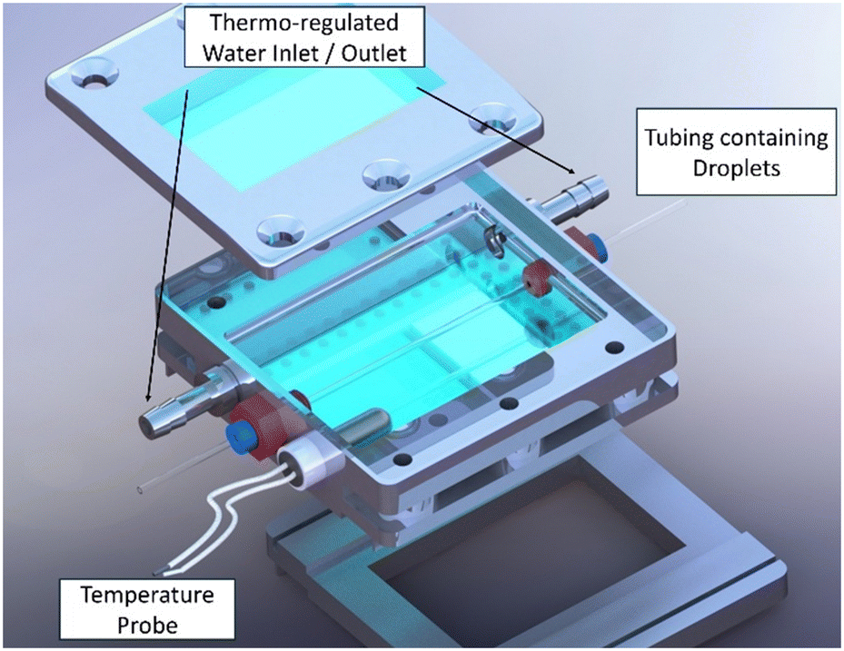 | ||
| Fig. 3 3D visualization of the 3D-printed sample holder designed for TPF and SHG microscopy observation of crystallization in droplet microfluidics. | ||
Monitoring crystallization by SHG microscopy in droplet microfluidics
Once the droplets are generated, the flow is stopped and the tube is stored within the sample holder at the desired temperature. The sample holder is mounted on a motorized X,Y stage which allows the droplets to be imaged sequentially as a function of time. This allowed characterization and counting of the number of crystals formed within each droplet.Batch crystallization
For preliminary trials, antisolvent and cooling crystallization was performed at the 100 mL scale in a 200 mL glass tube using a magnetic stirrer bar operating at 300 rpm. The temperature was controlled with a thermostated water bath. Crystals were recovered by filtration prior to X-ray analyses.X-ray diffraction
Crystals obtained from batch crystallization were characterized by powder X-ray diffraction (XRPD) using a D8 Discover diffractometer (Bruker Analytic X-ray Systems, Germany) with a Bragg–Brentano geometry. The instrument is equipped with a copper source (40 kV, 40 mA, λ = 1.5418 Å) and a Lynx EyeTM linear detector. The diffraction patterns were recorded at room temperature with a scan rate of 0.5 s per step of 0.04° (2θ) in the angular range of 3–30° 2θ. Data treatment was performed using Bruker Eva Software release 2018 V. Experimental XRPD patterns were compared to the patterns calculated from the crystal structures of o-ABA, retrieved from the CSD with refcodes AMBACO07 (FI), AMBACO05 (FII) and AMBACO08 (FIII).Results & discussion
1. Discrimination between o-ABA polymorphs by SHG/TPF microscopy
The three different polymorphs of o-ABA have been crystallized using the procedures described by Jiang et al.36,42 and characterized by X-ray powder diffraction and DSC (Fig. S1 and S2†). All results are consistent with previous studies.14We then characterized the three crystal forms of o-ABA by SHG/TPF microscopy. The corresponding Iemitted = f(λ) spectra obtained with illumination at 900 nm are shown in Fig. 4. Fig. 4a–c show that FI exhibits a sharp signal at 450 nm while FII and FIII are characterized by a wider emission occurring from 390 to 700 nm. The signal collected for FI is then attributed to SHG since FI is non-centrosymmetric.32 In line with the centrosymmetric nature of FII and FIII crystal packing, the signal emitted by these forms can only be associated with TPF.33,34
 | ||
| Fig. 4 Emitted signals for: (a) FI, (b) FII and (c) FIII crystals along with illustrative microscopy images (d, e and f) resulting from superimposition of the transmitted diffuse scattering and emitted signals detected in the epi configuration of FI (green), FII and FIII crystals (red). The vertical-axis corresponds to the measured intensity (a.u.) averaged over multiple areas (delimited only where crystals are present). | ||
To discriminate the crystal forms in our set-up, the emitted light was systematically collected at both 450 and 500 nm (with ±10 nm bandwidths): FII and FIII are thus characterized by emission at both wavelengths whereas a signal at 450 nm only is characteristic of FI. As for Raman spectroscopy, due to their similar TPF responses, FII and FIII are difficult to distinguish from SHG/TPF microscopy. Fig. 4d–f show the microscopy images of powdered samples of each crystal form illuminated at 900 nm superimposed to the emitted signals at 450 nm (shown in green) for FI and at 500 nm for FII and FIII (shown in red). The SHG emission wavelength and spectral bandwidth have been confirmed to be representative of the whole crystal and do not depend on the crystal thickness or orientation.
Fig. 5 shows the SHG/TPF microscopy images of two types of crystals (i.e., SHG or TPF emitting) from droplets in tubing. The fluorinated tubing does not jeopardize the SHG or TPF signal collection. Moreover, the microscopy images and nonlinear optical responses have been collected within less than one minute, which is an advantage compared to other imaging techniques such as confocal Raman microscopy.
 | ||
| Fig. 5 Emitted signals for: (a) SHG and (b) TPF emitting crystals along with illustrative microscopy images resulting from superimposition of the transmitted diffuse scattering and emitted signals detected in the epi configuration (c and d). In (a) and (b), the vertical-axis corresponds to the measured intensity (a.u.) averaged over multiple areas (delimited only where crystals are present). | ||
2. DM crystallization of o-ABA monitored by SHG/TPF microscopy
Jiang et al. investigated the anti-solvent crystallization of o-ABA from ethanol/water mixtures in continuously stirred reactors and used a Raman in situ probe for polymorph identification.37 Based on this work and to illustrate the benefit of our coupled platform, the crystallization of o-ABA in DM reactors was investigated to discriminate between the two forms.2-1. Determination of FI solubility in ethanol/water mixtures
In order to generate droplets with known supersaturations, it was first necessary to determine the saturation temperature corresponding to a given o-ABA concentration and ethanol/water mixtures. Solvent composition X is given as a ratio of volumes of the pure liquids (i.e., X = VEtOH/VH2O). The solubility of FI was therefore determined by gravimetry at T = 15, 20, 25, 30, 35 and 45 °C and at ethanol volume ratios of X = 0–100% with a 10% step increase. The obtained solubility curves were plotted and fitted with a 4 degree polynomial function and the corresponding surface is shown in Fig. 6. The solubility points are consistent with those obtained by Jiang et al. at 25 °C.37 The final solubility equation can be found in the ESI† (eqn S1). | ||
| Fig. 6 Surface plot of the solubility data points of FI as a function of temperature and ethanol ratio. | ||
2-2. Monitoring of the concomitant crystallization of o-ABA polymorphs by SHG/TPF microscopy
Since our DM experiments involve unstirred crystallization reactors and cooling crystallization conditions, we then analyzed the behavior of the system from unstirred 200 mL batch crystallizers using cooling crystallization with the same conditions (i.e., X = 50% and T = 25 °C) for reference. It should be underlined that the crystallization behavior of o-ABA under these conditions was unknown. As expected, the induction times for spontaneous crystallization were longer: the sample at β = 1.2 (Fig. S6†) resulted in single crystals of FI after several days (compared to several hours in the case of stirred crystallization). At β = 1.5 and 1.6, the XRPD signal of FII was detected after 40 minutes (compared to less than 10 minutes under stirring) but possibly a very minor fraction of FIII also formed in the sample at β = 1.6. In the absence of stirring, these crystals remained untransformed for at least 24 hours (Fig. S7 and S8†). At β = 2.2, the crystalline sample mostly consisted of FII but a minor fraction of FI was also detected (Fig. S9†). No FIII was observed in this sample. The results show that the absence of stirring drastically slows down the kinetics of solvent mediated transformation of FII into FI. Then, since very small XRPD signals of FIII were observed in these experiments, we chose to label any crystal exhibiting TPF activity as FTPF since the TPF signal cannot discriminate FII from FIII unambiguously. There is however a high probability that any FTPF crystals observed afterward consist of FII. For consistency, we also label any crystals exhibiting SHG as FSHG, but there is no ambiguity that FSHG is FI.
With the aim of studying the crystallization of FSHG and FTPF using our SHG/TPF DM set-up, the crystallization conditions were adapted to favor the kinetic competition between these two types of crystals within the droplets, notably in view to evidence any phenomenon of concomitant polymorphism. It is well known that reduction of the crystallization volumes has a strong impact on the induction time for spontaneous crystallization. To obtain the same induction times as those observed during batch crystallization for β = 1.5 and β = 1.6, it was necessary to increase the supersaturation to β = 2.2 (involving Tsat = 35.6 °C and Tcryst = 20 °C, see the Materials and methods section). Under these conditions, a large number of droplets with identical spherical volume (65 nL) and shape were generated, of which 37 of them were monitored by SHG/TPF microscopy every 30 minutes for at least 24 hours.
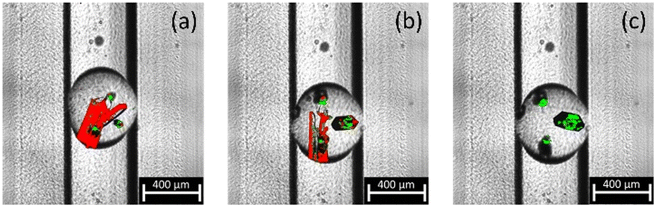
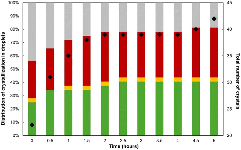
Crystallization occurred in almost every droplet within the first 30 minutes after their generation. If a few droplets contained only one single crystal, most of them resulted in the formation of several particles (2–6 crystals per droplet). Ex situ XPRD analyses were non-systematically performed using the combined content of several DM tubes: no trace of FIII was observed and the TPF signal can only be attributed to FII, hereby confirming that any FTPF is most likely FII. Fig. 7 reports the fraction of droplets that resulted in the crystallization of either FSHG, FTPF or both for the first 3 hours after droplet generation. Fig. 8 shows the SHG/TPF images of the typical droplet content during the monitoring. Each picture has been obtained in only 45 seconds which is a notable performance compared to other phase sensitive confocal imaging techniques that would require hours to image the whole droplet.
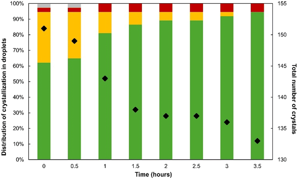 | ||
| Fig. 7 Histogram showing the fraction of droplets monitored by SHG/TPF that resulted in FSHG (green), FTPF (red), and both forms (yellow) for the first 3 hours after droplet generation at X = 50% and β = 2.2. The fraction of droplets that did not crystallize is shown in grey. The black dots report the total number of crystals in the 37 droplets over time. | ||
 | ||
| Fig. 8 Typical SHG/TPF images obtained after t = 0.5 hours of monitoring the DM crystallization experiment at X = 50% and β = 2.2. The green and red signals correspond to SHG or TPF signals, respectively. (a) Pure FSHG, (b) FPTF, and (c) the case of concomitant polymorphism. | ||
The results show that at this supersaturation and solvent ratio, the crystallization of pure FSHG occurred within ca. 60% of the droplets from the first 0.5 h after the generation of supersaturation. In contrast, droplets containing only FTPF account for only 3%. This suggests that the nucleation of FSHG is favored in small volumes since, at such levels of supersaturation, we have shown that batch crystallization should result in the formation of FII only.
In contrast, ca. 30% of droplets lead to the concomitant crystallization of both FSHG and FTPF within the first 30 minutes. This confirms that both types of crystals have similar nucleation rates and also explain the occurrence of droplets presenting a single crystal of either form. However, the fraction of droplets containing both forms was found to decrease down to 0% in 3 hours (Fig. 7). The transition is illustrated by the TPF/SHG pictures in Fig. 9 which shows the progressive dissolution of FTPF crystals and the growth of pre-existing FSHG crystals. Video S10 illustrating this transition can be found in the ESI.† The overall number of crystals was found to decrease during our experiment (Fig. 7, black dots) as a result of this transformation. This confirms that the solvent mediated conversion of FII into FI is strongly accelerated by the presence of FI pre-existing crystals. This also agrees with the fact that the number of droplets containing only FTPF crystals did not evolve within the timeframe of our experiment.
 | ||
| Fig. 9 Typical SHG/TPF images showing the solvent mediated disappearance of FTPF to the benefit of FSHG in a droplet that initially contained both forms. (a) 0.5 hours, (b) 3 hours and (c) 4 hours. | ||
After 3 hours of observation, the content of the droplets remained virtually unchanged. However, on one occasion, we observed the transition from a single crystal of FTPF into a FSHG single crystal. This transition started 4 hours after droplet generation and was completed only after 8 hours of monitoring.
As seen from the SHG/TPF observations (Fig. 10), the transition seems to occur with an even slower mechanism, and may correspond to a solid–solid transition that does not imply the dissolution of FTPF. Video S11 illustrating this phenomenon can be found in the ESI.† This result highlights that our SHG/TPF set-up is capable of tracking different types of phase transitions within micro-sized reactors. Actually, after months of storing at room temperature, all crystals in the droplets ended up transforming into FSHG crystals (i.e. stable form FI).
 | ||
| Fig. 10 Typical SHG/TPF images showing the solid–solid transformation of a single crystal of FTPF into FSHG within a droplet. (a) 0.5 hours, (b) 4 hours and (c) 8 hours. | ||
 | ||
| Fig. 11 Histogram showing the fraction of droplets monitored by SHG/TPF that resulted in FSHG (green), FTPF (red), and both forms (yellow) for the first 5 hours after droplet generation at X = 20% and β = 3. The fraction of droplets that did not crystallize is shown in grey. The black dots report the total number of crystals in the 32 droplets over time. | ||
The results show that crystallization occurs in more than 50% of the droplets before the first 30 min and reaches a maximum of ca. 80% after 5 hours. Around ⅔ of the crystallized droplets lead to the appearance of a single crystal. The other droplets contain most often two crystals and rarely three or four crystals. This results in a substantial reduction of the total number of crystals compared to the previously investigated conditions (i.e., X = 50% and β = 2.2). The total number of crystals increases during the experiment both due to the dynamics of crystallizing droplets and to the absence of transition between polymorphs.
Fig. 11 also shows that most droplets contain only one polymorph. Interestingly, the number of droplets containing FTPF is similar to the number of droplets containing FSHG. This is a notable difference with reference to the experiment performed at X = 50% (Fig. 7) but is likely a consequence of the higher supersaturation. Fig. 12 shows the typical SHG/TPF pictures of crystals in droplets containing a single form. It also shows that the average crystal size is strongly reduced under these conditions but that the SHG/TPF microscope remains sufficiently sensitive to discriminate between the two types of crystals.
 | ||
| Fig. 12 Typical SHG/TPF images obtained after t = 0.5 hours of monitoring the DM crystallization experiment at X = 20% and β = 3. The green and red signals correspond to FSHG or FTPF, respectively. (a) Pure FSHG, (b) pure FTPF, and (c) the case of concomitant polymorphism. | ||
Further to this, the number of droplets exhibiting both forms is ten times lower in this experiment. Actually, during the first 30 minutes of monitoring, only one droplet exhibiting concomitant polymorphism was observed (Fig. 12c) for which FTPF rapidly transformed into FSHG. Then, the same situation occurred in another single droplet crystallizing after 1 h. However, no conversion of FTPF was detected during further monitoring.
Conclusions
A new analytical set-up allowing monitoring of small volume crystallization was presented by coupling DM and SHG/TPF microscopy. The performance of this device allows rapid imaging of the droplet content and fast SHG and TPF signal detection, making it an efficient monitoring tool for microfluidic crystallization for adapted systems, with a satisfactory time and space resolution.In this work, we described how our set up can be used to investigate crystallization behaviors from small volume reactors and to evidence phenomena such as concomitant polymorphism. The benefit of this device has been illustrated by monitoring the crystallization of o-ABA from DM in ethanol/water solvent mixtures. First, SHG emission permits crystals of FI to be non-ambiguously identified. The TPF response was useful to evidence crystals of FTPF although it remains difficult to discriminate FII from FIII due to similar TPF responses. Second, the temporal resolution of this device permits evidencing and imaging solvent-mediated transitions, as well as solid–solid conversion of what is most likely FII into FI. We observed in particular that the stable form (FI) is favored in small volumes. The results of our crystallization experiments are in good agreement with previous studies that used PAT techniques to identify o-ABA polymorphs, which shows that our approach can be used in combination with these technologies.
Therefore, this new crystallization set-up offers new possibilities to monitor and image crystallization within microfluidic chips, in particular in the presence of non-centrosymmetric phases. This could be particularly useful in the field of chiral molecules in which the portion of non-centrosymmetric structures is constantly increasing. Furthermore, it could also be envisaged to discriminate between two centrosymmetric crystal forms provided that their TPF responses differ sufficiently.
Data availability
Data for this article, including XRPD patterns and thermograms of all o-ABA polymorphs, equation of the solubility as a function of temperature and ethanol volume percentage, time-resolved ex situ XRPD monitoring of o-ABA antisolvent crystallization for supersaturations of β = 1.5, 1.6 and 1.8 and unstirred cooling crystallization for supersaturations of β = 1.2, 1.5, 1.6 and 2.2 at X = 50% of solvent composition, video of solvent-mediated transition from a mixture of FSHG and FTPF to FSHG only and solid–solid transformation from FTPF to FSHG, time-resolved ex situ XRPD monitoring of o-ABA unstirred cooling crystallization for supersaturation of β = 3 at X = 20% of solvent composition are available at ESI.†Author contributions
HC (investigation, writing – original draft, conceptualization), CB (writing – review and editing, supervision), RR (resources), CP & CJJG (conceptualization), SV, NC & RG (methodology, writing – review and editing), VD (writing – review and editing, supervision).Conflicts of interest
There are no conflicts to declare.Acknowledgements
A. Echalard and C. de Lartigue (UMR6270 CNRS Polymères, Biopolymères, Surfaces (PBS) - Equipe BIOMMAT, Université de Rouen Normandie, France) are greatly acknowledged for their support regarding the design and 3D printing of the sample holder.References
- C. Park, J. E. Park and H. C. Choi, Acc. Chem. Res., 2014, 47, 2353–2364 CrossRef CAS PubMed.
- J. Chen, B. Sarma, J. M. B. Evans and A. S. Myerson, Cryst. Growth Des., 2011, 11, 887–895 CrossRef CAS.
- W. D. Callister and D. G. Rethwisch, Materials Science and Engineering: An Introduction, Wiley, 10th edn, 2018 Search PubMed.
- R. W. Hartel, in Handbook of Industrial Crystallization, ed. A. S. Myerson, Butterworth-Heinemann, Woburn, 2nd edn, 2002, pp. 287–304 Search PubMed.
- Q. Shi, H. Chen, Y. Wang, J. Xu, Z. Liu and C. Zhang, Int. J. Pharm., 2022, 611, 121320 CrossRef CAS PubMed.
- J. Anwar and D. Zahn, Adv. Drug Delivery Rev., 2017, 117, 47–70 CrossRef CAS PubMed.
- J. Bernstein, R. J. Davey and J.-O. Henck, Angew. Chem., Int. Ed., 1999, 38, 3440–3461 CrossRef PubMed.
- J. Nyman and G. M. Day, CrystEngComm, 2015, 17, 5154–5165 RSC.
- S. Srisanga and J. H. ter Horst, Cryst. Growth Des., 2010, 10, 1808–1812 CrossRef CAS.
- H. Yang and A. J. Florence, CrystEngComm, 2017, 19, 3966–3978 RSC.
- C. Brandel and J. H. ter Horst, Faraday Discuss., 2015, 179, 199–214 RSC.
- D. Law and D. Zhou, in Developing Solid Oral Dosage Forms, ed. Y. Qiu, Y. Chen, G. G. Z. Zhang, L. Yu and R. V. Mantri, Academic Press, Boston, 2nd edn, 2017, pp. 59–84 Search PubMed.
- V. R. Vázquez Marrero, C. Piñero Berríos, L. De Dios Rodríguez, T. Stelzer and V. López-Mejías, Cryst. Growth Des., 2019, 19, 4101–4108 CrossRef PubMed.
- E. Simone, J. McVeigh, N. M. Reis and Z. K. Nagy, Lab Chip, 2018, 18, 2235–2245 RSC.
- N. Candoni, R. Grossier, M. Lagaize and S. Veesler, Annu. Rev. Chem. Biomol. Eng., 2019, 10, 59–83 CrossRef PubMed.
- Y. Zhu and Q. Fang, Anal. Chim. Acta, 2013, 787, 24–35 CrossRef CAS PubMed.
- B. Zheng, L. S. Roach and R. F. Ismagilov, J. Am. Chem. Soc., 2003, 125, 11170–11171 CrossRef CAS PubMed.
- M. Lambert, R. Grossier, M. Lagaize, T. Bactivelane, V. Heresanu, B. Robert, N. Candoni and S. Veesler, J. Cryst. Growth, 2023, 616, 127252 CrossRef CAS.
- M. P. Cecchini, J. Hong, C. Lim, J. Choo, T. Albrecht, A. J. deMello and J. B. Edel, Anal. Chem., 2011, 83, 3076–3081 CrossRef CAS PubMed.
- I. Lignos, S. Stavrakis, A. Kilaj and A. J. deMello, Small, 2015, 11, 4009–4017 CrossRef CAS PubMed.
- J. Probst, C. N. Borca, M. A. Newton, J. van Bokhoven, T. Huthwelker, S. Stavrakis and A. deMello, ACS Meas. Sci. Au, 2021, 1, 27–34 CrossRef CAS PubMed.
- R. Stehle, G. Goerigk, D. Wallacher, M. Ballauff and S. Seiffert, Lab Chip, 2013, 13, 1529–1537 RSC.
- N. Pham, D. Radajewski, A. Round, M. Brennich, P. Pernot, B. Biscans, F. Bonneté and S. Teychené, Anal. Chem., 2017, 89, 2282–2287 CrossRef CAS PubMed.
- C. J. J. Gerard, G. Ferry, L. M. Vuillard, J. A. Boutin, L. M. G. Chavas, T. Huet, N. Ferte, R. Grossier, N. Candoni and S. Veesler, Acta Crystallogr., Sect. F:Struct. Biol. Commun., 2017, 73, 574–578 CrossRef CAS PubMed.
- M. A. Levenstein, C. Anduix-Canto, Y.-Y. Kim, M. A. Holden, C. González Niño, D. C. Green, S. E. Foster, A. N. Kulak, L. Govada, N. E. Chayen, S. J. Day, C. C. Tang, B. Weinhausen, M. Burghammer, N. Kapur and F. C. Meldrum, Adv. Funct. Mater., 2019, 29, 1808172 CrossRef.
- P. Pattanayak, S. K. Singh, M. Gulati, S. Vishwas, B. Kapoor, D. K. Chellappan, K. Anand, G. Gupta, N. K. Jha, P. K. Gupta, P. Prasher, K. Dua, H. Dureja, D. Kumar and V. Kumar, Microfluid. Nanofluid., 2021, 25, 99 Search PubMed.
- P. A. Franken and J. F. Ward, Rev. Mod. Phys., 1963, 35, 23–39 CrossRef CAS.
- S. A. Denev, T. T. A. Lummen, E. Barnes, A. Kumar and V. Gopalan, J. Am. Ceram. Soc., 2011, 94, 2699–2727 Search PubMed.
- P. Theer, B. Kuhn, D. Keusters and W. Denk, in Reviews in Cell Biology and Molecular Medicine, John Wiley & Sons, Ltd., 2006 Search PubMed.
- K. Flügel, Q. Tian and L. Kaestner, in Microscopy of the Heart, ed. L. Kaestner and P. Lipp, Springer International Publishing, Cham, 2018, pp. 21–35 Search PubMed.
- F. Poulon, J. Pallud, P. Varlet, M. Zanello, F. Chretien, E. Dezamis, G. Abi-Lahoud, F. Nataf, B. Turak, B. Devaux and D. Abi Haidar, Sci. Rep., 2018, 8, 14888 Search PubMed.
- C. J. Brown and M. Ehrenberg, Acta Crystallogr., Sect. C:Cryst. Struct. Commun., 1985, 41, 441–443 CrossRef.
- C. D. G. Boone, J. L. Derissen and J. C. Schoone, Acta Crystallogr., Sect. B, 1977, 33, 3205–3206 Search PubMed.
- H. Takazawa, S. Ohba and Y. Saito, Acta Crystallogr., Sect. C:Cryst. Struct. Commun., 1986, 42, 1880–1881 Search PubMed.
- S. Dinagaran, P. Srinivasan, S. Vijayakumar and J. Balaji, J. Adv. Chem., 2016, 12, 4480–4487 CrossRef CAS.
- S. Jiang, P. J. Jansens and J. H. ter Horst, Cryst. Growth Des., 2010, 10, 2541–2547 Search PubMed.
- S. Jiang, J. H. ter Horst and P. J. Jansens, Cryst. Growth Des., 2008, 8, 37–43 CrossRef CAS.
- E. Simone, M. V. Cenzato and Z. K. Nagy, J. Cryst. Growth, 2016, 446, 50–59 CrossRef CAS.
- Scilab Copyright© 1989–2005. INRIA ENPC (version 2024) INRIA.
- G. Peybernès, R. Grossier, F. Villard, P. Letellier, N. Candoni and S. Veesler, Cryst. Growth Des., 2020, 20, 3882–3887 CrossRef.
- G. Peybernès, R. Grossier, F. Villard, P. Letellier, M. Lagaize, N. Candoni and S. Veesler, Org. Process Res. Dev., 2018, 22, 1856–1860 CrossRef.
- S. Jiang, P. J. Jansens and J. H. ter Horst, Cryst. Growth Des., 2010, 10, 2123–2128 CrossRef CAS.
- E. Simone, A. N. Saleemi, N. Tonnon and Z. K. Nagy, Cryst. Growth Des., 2014, 14, 1839–1850 CrossRef CAS.
Footnote |
| † Electronic supplementary information (ESI) available. See DOI: https://doi.org/10.1039/d4ce01289e |
| This journal is © The Royal Society of Chemistry 2025 |