
Mechanisms of interlayer friction in low-dimensional homogeneous thin-wall shell structures and its strain effect†
Yi
Cai
a,
Jianzhang
Huang
 *a,
Shuang
Gan
a,
Yingjing
Liang
a,
Kejing
Wang
a and
Qiang
Han
b
*a,
Shuang
Gan
a,
Yingjing
Liang
a,
Kejing
Wang
a and
Qiang
Han
b
aDepartment of Engineering Mechanics, School of Civil Engineering and Transportation, Guangzhou University, Guangzhou, Guangdong Province 510006, People's Republic of China. E-mail: jhuang@gzhu.edu.cn
bSchool of Civil Engineering and Transportation, South China University of Technology, Guangzhou, 510640, People's Republic of China
First published on 25th November 2024
Abstract
Due to the multi-factor coupling effect, the rule of interlayer friction in low-dimensional homogeneous thin-wall shell structures is still unclear. Double walled carbon nanotubes (DWCNTs) having a typical low-dimensional homogeneous thin-wall shell structure are selected for this study. The interlayer friction of numerous chiral DWCNTs is investigated using molecular dynamics simulations to systematically analyze and understand the coupling mechanisms of various factors in interlayer friction. To eliminate the influence of the edge effect, a high-speed pure rotation model is used. The results demonstrate that DWCNTs with varying mismatch angle, interlayer distance, and interfacial radius exhibit distinct interlayer frictions and strain effects, due to the differences in interlayer interaction, atomic vibrational amplitudes, and lattice periods. Theoretical analysis is conducted on the interlayer friction and its strain effect based on the theoretical model. Based on phonon spectrum analysis, the vibrational modes and energy dissipation of DWCNTs with different chiral combinations under various strains are demonstrated. Based on the analysis, physical insight into the variation in friction forces is provided. The findings of this work deepen the understanding of the interlayer friction and strain mechanism and provide a theoretical basis for further exploitation of the strain effect to realize the regulation of nanoelectromechanical devices.
1 Introduction
Recently, friction in low-dimensional homogeneous thin-wall shell structures at the nanoscale has emerged as a hot spot in the field of tribology research.1 In comparison to friction in high-dimensional materials at the macroscopic scale, nanoscale friction in low-dimensional structures is influenced by intricate surface effects. Therefore, friction at the nanoscale is often subject to the coupling influence of multiple factors revealing complex mechanisms of frictional impact.2,3 Owing to their relatively perfect surface structure nanomaterials, carbon based low-dimensional homogeneous thin-wall structures such as graphene, fullerene, and nanotubes are ideal research objects in the field of nanotribology in low-dimensional homogeneous materials.4–7 The excellent electromagnetic, thermodynamic, chemical, and mechanical properties of CNTs make them highly promising for a wide range of uses, including in nanolubricants, nanopropulsion, and nanotransmission.8–17 The strong toughness and low interlayer van der Waals (vDW) interactions of DWCNTs make them an ideal component for nano-electro-mechanical systems (NEMSs).18,19 Therefore, DWCNTs are selected as the research objects of this study.Restricted by the techniques of manipulation and characterization at the nanoscale of CNTs, only a few researchers have been able to measure the interlayer friction of DWCNTs experimentally.18,20 Cumings et al. observed extremely low static and dynamic interlayer friction in DWCNTs, with the dynamic interlayer friction being lower than 1.5 × 10⁻¹⁴ N per atom, through “pull-out” experiments.21 Kis et al. measured and obtained extremely low interlayer friction in DWCNTs using transmission electron microscopy, as well as remarkably low energy dissipation.22 Ye et al. determined that the interlayer friction of ultra-long DWCNTs stabilized at around 2 nN using the lateral loading method.23 The MD method has also been performed to investigate the tribological properties of nanomaterials. Compared to experimental methods, MD simulation, which can avoid interference from environmental factors, offers a new approach to studying mechanical behavior and mechanisms at the nanoscale.24,25 Zhang et al. discovered that DWCNT bearings exhibit extremely low friction coefficients during pure rotational processes through the MD process.26 Furthermore, the superlubricity of carbon-based materials is primarily attributed to their perfect crystal lattice structure. However, altering the crystal lattice structure, such as through the presence of defects or functionalization of carbon atoms, can lead to variations in the interactions and ultimately result in changes in interlayer friction.27 Guo et al. performed molecular dynamics simulation to measure friction forces directly and found that defects in CNTs result in an increase in interlayer friction during relative sliding processes.28 Vander Wal et al. found that fluorinated CNTs exhibit lower friction coefficients compared to non-fluorinated CNTs through experiments.29 Although the interlayer friction of DWCNTs is relatively low, it is still affected by multi-factor coupling similar to other nanomaterials. Therefore, the variation law of interlayer friction cannot be ignored. Firstly, CNTs with different chirality possess distinct chiral angle and radius. As a result, DWCNTs formed by their combination exhibit variations in mismatch angle, interlayer distance, and interfacial radius, which result in variations in the frictional properties of DWCNTs. Hence, it is possible to alter the frictional properties of DWCNTs by choosing CNTs with different chirality for combination. Kolmogorov et al. found that incommensurate contact DWCNTs exhibit smaller interlayer friction compared to commensurate DWCNTs, through MD simulations.30 Wu et al. discovered that DWCNTs with different chirality combinations result in varying friction forces during the “pull-out” simulations.31 Li et al. found that the energy consumed by interlayer friction in DWCNTs increases with the growth of the interfacial radius.32 Previous research indicated that, besides intrinsic factors of CNTs, external conditions such as environmental temperature can also result in variations in the tribological performance of DWCNTs. Guo et al. found that the tribological properties of DWCNTs can be controlled by tuning the temperature during the MD process, especially the carbon atoms at the edge, as the distinction of temperature can influence the potential barriers and interlayer interactions of CNTs.33 Additionally, various experimental and simulation studies have indicated that the state of relative motion induces varying dynamic interlayer interactions during the relative movement of DWCNTs, resulting in distinct frictional properties. Zhang et al. experimentally found that interlayer friction increases with the velocity of movement in the “pull-out” experiment for centimeter-scale CNTs.34 Cook et al. discovered that in the case of pure rotation of DWCNTs, interlayer friction increases with the rotational speed with MD simulations. They also pointed out that there are differences in interlayer tribological properties between different relative motion modes of DWCNTs, such as the edge effect.25,35 Zhao et al. found that CNTs possess extremely high strength and toughness through theoretical studies, providing feasibility for applying strain to alter the frictional properties of DWCNTs.36 Through molecular dynamics simulations, Huang et al. found that tribological properties of commensurate DWCNTs can be modified by axial or torsional strain during pure rotation, which changes the dependence on temperature and speed of relative motion.37,38 Li et al. discovered that in the case of relative sliding of incommensurate DWCNTs, their tribological properties can be changed by tensile strain by using MD simulations.39
Fennimore et al. first built a nanoactuator with a multi-walled carbon nanotube (MWCNT) function as the key motion-enabling element.40 Barreiro et al. reported that a combinational motion of translational motion and axial rotation in the outer tube was generated by the application of direct current to the inner tube of a DWCNT.41 These findings on the phenomenon of CNT actuators have attracted a lot of research work on the new generation of nanoactuators based on low-dimensional thin-wall materials.33,42,43 However, these research studies mainly focus on translational motion rather than rotational motion. Cai et al. discovered that pure rotation occurs in the inner tube of the DWCNT by fixing the outer tube of the DWCNT at room temperature.44 Huang et al. proposed a pure rotation model of the DWCNT actuator and pointed out the thermally induced driving force against interlayer friction throughout the rotational process, especially at a high rotational speed.45 In addition, for NEMSs, as sizes decrease and operational speeds increase, controlling the energy dissipation generated by friction becomes increasingly crucial. Therefore, research on the energy dissipation generated by the friction of low dimensional thin-walled structures under high-speed plays a vital role in effectively reducing the energy consumption of NEMSs in practical engineering applications.46,47 Previous studies indicate that the tribological properties of low dimensional thin-walled nanomaterials can be markedly influenced by the lattice structure which is related to the chirality of low dimensional thin-walled materials. In practical production processes, the chirality of CNTs is often influenced by the growth environment. As a result, growing DWCNTs with regular chiral combinations can be challenging.48–50 Additionally, research studies indicate that the properties of nanomaterials can be influenced by the application of strain significantly. In practical engineering applications, it is often necessary to apply strain to CNTs to meet the requirements of engineering.51–53 Moreover, owing to the involvement of intricate surface effects in the interlayer friction of DWCNTs, delving into the coupled effects of various factors is conducive to a comprehensive and profound understanding of friction at the nanoscale and its mechanisms of energy dissipation. However, existing studies have a narrow focus on the individual influence mechanisms of interlayer friction for specific factors. Additionally, most research models use “pull-out” sliding DWCNTs and assume low-speed relative sliding. Currently, there are scarce research studies on the differences in interlayer friction and its strain effects on DWCNTs with different chiral combinations under high-speed pure rotation conditions. The mechanisms of the multi-factor coupled effect behind interlayer friction and its strain effect, influenced by variations in interlayer distance, mismatch angle, and interfacial radius due to different chiral combinations of DWCNTs and the application of strain, have not been thoroughly investigated.
In this research, a model of DWCNTs undergoing high-speed rotation is employed to eliminate edge effects. MD simulations have been performed to study the impact of interlayer distance, mismatch angle, and interfacial radius on interlayer friction caused by the difference in different chiral combinations and the coupling effects of influencing factors on interlayer friction from the perspective of energy dissipation. Additionally, this study investigated the tensile, compressive, and torsional strain effects on the interlayer friction of DWCNTs with different chiral combinations. Theoretical model analysis and phonon density of states analysis are used to obtain meaningful discoveries. The mechanisms of the influences of chiral combinations and strain effect on low dimensional thin-walled structures are explored.
2 Simulation model and methods
2.1 Molecular dynamic model
This study investigated the interlayer friction of DWCNT bearings in two commensurate combination types namely (n,0)-(n,0) and (n,n)-(n,n), as well as three incommensurate combination types namely (n,0)-(n,m), (n,m)-(n,m), and (n,n)-(n,m). Fig. 1a illustrates the DWCNT bearing system adopted in the MD simulations. In this system, carbon atoms in region 1 are configured to rotate around the z-axis at a constant angular velocity. The carbon atoms in region 2 follow the motion of those in region 1. The carbon atoms in region 3 are free and connected to the Nose–Hoover thermostat for temperature control. During the entire simulation, the velocities and positions of atoms in region 3 are monitored and adjusted at each time step to maintain the temperature of this region. Carbon atoms in region 4 are fixed through the simulations, and strains are applied by displacing the atoms. The temperature of carbon atoms in region 2 is maintained at the system temperature.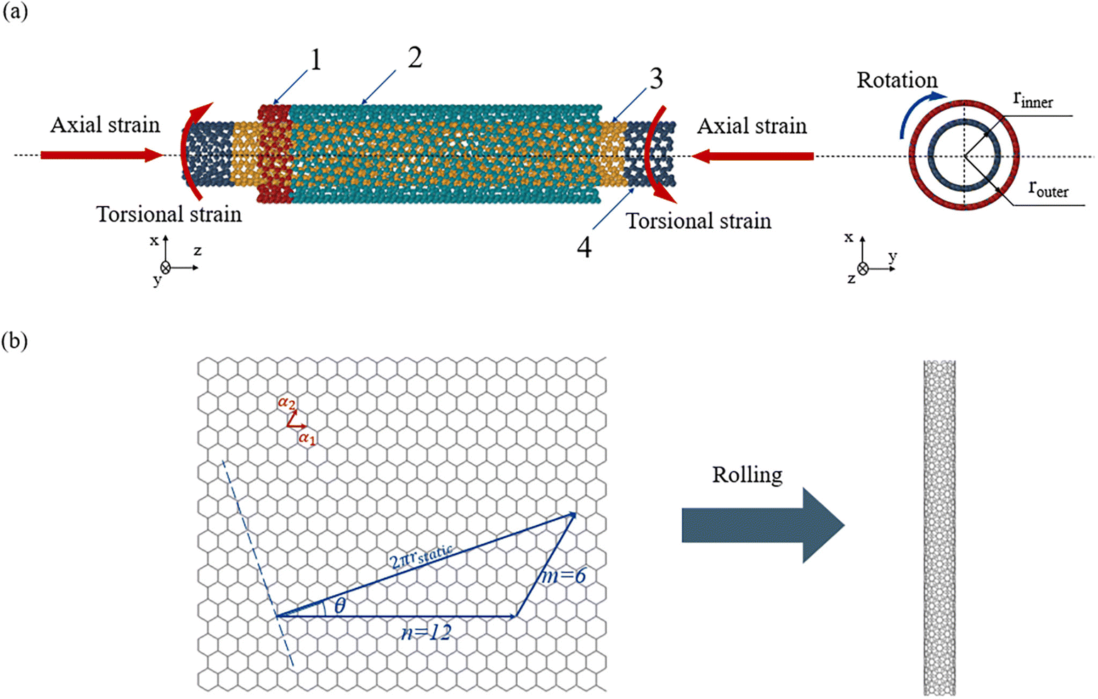 | ||
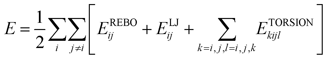
| Fig. 1 (a) Physical model of the DWCNT bearing system with the chiral combination (12,6)-(15,13), including the division of the regions, the motion way of the outer tube, and the strain loading method on the inner tube. (b) Schematic diagram of CNT formation and the relationship between the chiral index and the chiral angle, where α1 and α2 are the unit lattice vectors of the unfolded graphene. | ||
Large-scale atomic/molecular massively parallel simulator (LAMMPS) is employed to conduct molecular dynamics simulations.54 In this system, the C–C bonds in each SWCNT are modeled using the adaptive intermolecular reactive empirical bond order potential (AIREBO) potential function.55
 | (1) |
Among them, EREBOij represents the bond order potential, ELJij is the long-range interaction potential, and ETORSIONkijl is the four-body torsion potential. This potential function is currently the most widely used in the study of the mechanical properties of carbon nanomaterials, and its accuracy has been widely recognized.56,57 The van der Waals interaction between the inner and outer tube layers is described by:
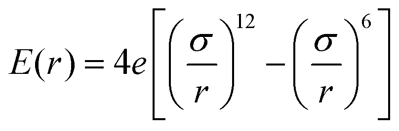 | (2) |
The global simulation box is set with periodic boundaries in the x and y directions and a shrinking boundary in the z direction. The time step of this simulation is configured to dt = 1 fs. Energy minimization is performed at the beginning of the simulations. Subsequently, the CNTs are thoroughly relaxed under the Langevin thermostat to achieve the minimum potential energy.58 In the investigation of strain effects, axial or torsional strains will be applied to region 4 on both sides of the inner tube. ε = (L − L0)/L0 defines the axial strain, where L0 and L are the length of inner tube before and after deformation, respectively, and φ is defined as the rotational angle. During the high-speed pure rotation process, the outer tube rotates with an angular velocity of ω = 150 GHz, completing 100 rounds in each simulation.
The interlayer distance and interfacial radius are both calculated from the dynamic radius obtained from rotational inertia calculated during the whole rotational process. The formula for calculating the rotational inertia is as follows:
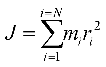 | (3) |
![[r with combining macron]](https://www.rsc.org/images/entities/i_char_0072_0304.gif) = (rinner + router)/2 is the value of the interfacial radius, Δr = router − rinner is the value of interlayer distance where rinner and router represent the dynamic radius of the inner tube and outer tube. As a 1D nanomaterial, CNTs can be regarded as tubular structures formed by the rolling of graphene sheets, with their basic structural characteristics determined by the rolling vectors of the graphene sheets.59Fig. 1b demonstrates the formation mode of CNTs and the relationship between the chiral index and the chiral angle. The chiral angle of the CNT can be calculated as follows:
= (rinner + router)/2 is the value of the interfacial radius, Δr = router − rinner is the value of interlayer distance where rinner and router represent the dynamic radius of the inner tube and outer tube. As a 1D nanomaterial, CNTs can be regarded as tubular structures formed by the rolling of graphene sheets, with their basic structural characteristics determined by the rolling vectors of the graphene sheets.59Fig. 1b demonstrates the formation mode of CNTs and the relationship between the chiral index and the chiral angle. The chiral angle of the CNT can be calculated as follows: | (4) |
2.2 Friction calculation method
Friction is calculated using a steady-state isothermal method, and the Nose–Hoover thermostat will be employed to compute and adjust the thermodynamic temperature of the carbon atoms.35,60 While rotating, the thermal energy generated by interlayer friction will be extracted by the thermostat to maintain the constant temperature of the system. The relationship between energy dissipation and dissipation rate is as follows: | (5) |
 | (6) |
3 Results and discussion
3.1 Effect of interlayer distance
The lattice structure of CNTs exhibits distinction during their manufacturing and motion processes, resulting in differences in their radius which will have an impact on the interlayer distance.61Fig. 2 demonstrates the relationship between interlayer friction of DWCNTs with different Δr.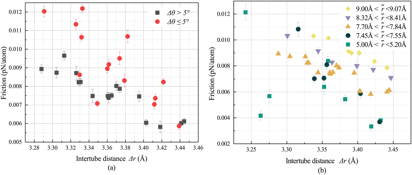 | ||
| Fig. 2 (a) The variation in interlayer friction which corresponds to DWCNTs of different chiral combinations with the distinction of Δr for DWCNTs with Δθ > 5° and Δθ ≤ 5° and ranging from 7.70 Å to 7.84 Å. (b) The variation in interlayer friction which corresponds to DWCNTs of different chiral combinations with distinction of Δr for DWCNTs with Δθ > 5° and different . | ||
Dienwiebel et al. conducted experimental research on the variation of interlayer friction in a friction pair model consisting of graphene with changing mismatch angle.62 Their findings indicated that the friction between graphene layers reaches a relatively stable super-lubricated state when the Δθ exceeds 5°. Due to the similarity between the high-speed pure rotational DWCNT models and the sliding graphene friction pairs, the DWCNTs are categorized into two groups: Δθ > 5° and Δθ ≤ 5°. is restricted between 7.70 and 7.84 Å, to investigate the interlayer friction variation with the interfacial radius of DWCNTs with different Δθ. As illustrated in Fig. 2a, whether the Δθ is greater than 5° or not, the interlayer friction tends to decrease with the increase in Δr. The results of interlayer friction for DWCNT chiral combinations of other are shown in the ESI,† Section S1. Moreover, DWCNTs with Δθ > 5° often exhibit lower interlayer friction than DWCNTs with the Δθ ≤ 5° under similar Δr. When the Δθ ≤ 5°, the interlayer friction between SWCNTs with Δr of 3.44 Å decreased by 51.85% compared to the DWCNTs with Δr of 3.29 Å. However, the friction reduction ratio is reduced to 43.25%, while Δθ > 5°. For DWCNTs with Δθ > 5°, the interlayer friction decreases almost monotonically with the increase of Δr. In contrast, for DWCNTs with Δθ ≤ 5°, the interlayer friction does not exhibit a monotonous change with increasing Δr. Variations in interlayer friction emerge under similar Δr due to differences in chirality. The result indicates that DWCNTs with smaller Δθ exhibit higher sensitivity to Δr compared to those with larger Δθ. However, the effect of the lubrication is unpredictable while increasing the Δr for DWCNTs with Δθ ≤ 5 under high-speed rotation. For the DWCNTs with larger Δθ, the influence of Δr variation on interlayer friction becomes more stable, making the Δr the primary factor affecting interlayer friction in this case. Therefore, for DWCNTs with larger Δθ, friction can be reduced by selecting DWCNTs with larger Δr. Conversely, for DWCNTs with smaller Δθ, more attention should be paid to the chiral combination of the SWCNTs when choosing specific DWCNTs with larger Δr for lubrication.
Due to the fact that interlayer friction between CNTs at similar almost monotonically decreases with the increase in Δr, when the Δθ of DWCNTs exceeds 5°, in studying the relationship between interlayer friction and Δr under different , DWCNTs with Δθ > 5° are selected and divided into five groups based on : 5.00–5.20 Å, 7.45–7.55 Å, 7.70–7.84 Å, 8.32–8.41 Å, and 9.00–9.07 Å, with the Δr ranging from 3.24 Å to 3.45 Å.
As demonstrated in Fig. 2b, it can be determined that interlayer friction of DWCNTs with different exhibit a decreasing trend with the increase in Δr. DWCNTs with larger and similar Δr exhibit greater interlayer friction and the influence of Δr variation on interlayer friction becomes more stable at the same time. As a result, for DWCNTs with Δθ > 5° and larger , the reduction in interlayer friction can be achieved by selecting suitable chiral combinations to increase Δr. However, for DWCNTs with smaller , other factors like Δθ need to be taken into consideration.
3.2 Effect of mismatch angle
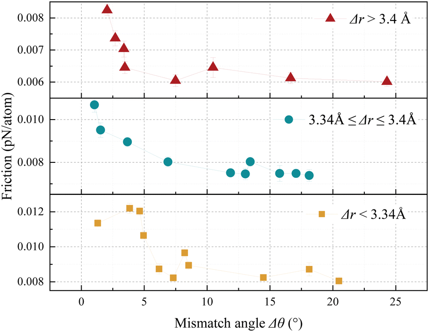
Existing literature studies have demonstrated that the lubricating effect of solids under dry conditions is associated with the commensurate state of the contact surfaces.63,64 The Δθ plays a vital role in influencing the incommensurate state. Fig. 3 illustrates the relationship between the interlayer friction and Δθ under incommensurate contact. The results of interlayer friction for DWCNT chiral combinations of other are shown in the ESI† Section S1. The Δr of DWCNTs is maintained between 7.7 Å and 7.85 Å, with the Δr controlled within three ranges: below 3.34 Å, between 3.34 Å and 3.4 Å, and above 3.4 Å. The mismatch angle varies from 0 to 25°. It can be observed from Fig. 7 that DWCNTs with three sets of different Δr exhibit a decreasing trend in interlayer friction with the increase in Δθ. This trend is similar to the variation in patterns of interlayer friction with mismatch angle reported by Zhang et al. and Dienwiebel et al. in graphene friction pairs, as well as the variation in patterns of interlayer friction with mismatch angle reported by Li et al. in sliding DWCNTs.39,62,65 It is also found that DWCNTs with smaller Δθ exhibit greater friction when they possess a similar interlayer distance and interfacial radius. Furthermore, the lubricating effects resulting from the increase in Δθ differ for DWCNTs with different Δr. Table 1 presents the proportions by which the interlayer friction decreases with the increase in Δθ for DWCNTs with different Δr. The result reveals that the lubricating effect caused by the increasing Δθ of DWCNTs with similar is improved by the reduction in Δr significantly. Therefore, for high-speed rotating DWCNT bearings, selecting chiral combinations with larger Δθ can effectively reduce friction, especially for DWCNTs with smaller Δr.
 | ||
| Fig. 3 The relationship between the interlayer friction which corresponds to DWCNTs with different chiral combinations and the Δθ. The is set between 7.7 Å and 7.85 Å. | ||
| Δr (Å) | <3.34 | 3.34–3.4 | >3.4 |
|---|---|---|---|
| Variation (%) | 34.04 | 30.87 | 27.06 |
3.3 Effect of interfacial radius
Zhou et al. determined that DWCNTs with different interfacial radii exhibit interlayer attraction proportional to the interfacial radius, which implies that the interfacial radius is one of the factors that influence interlayer interactions.66 To avoid the influence of Δr and Δθ, the study on interlayer friction of DWCNTs under commensurate contact is conducted first. The relationship between the variation in interlayer friction of armchair and zigzag DWCNTs and ranging from 0.45 nm to 1.15 nm is illustrated in Fig. 4. For commensurate contacted DWCNTs, the has a significant impact on the interlayer friction. For zigzag DWCNTs, the interlayer friction of DWCNTs with an of 11.30 Å is 0.583 pN per atom higher than that with an of 5.40 Å. Similarly, for armchair DWCNTs, the interlayer friction of DWCNTs with an of 11.30 Å is 1.05 pN per atom higher than that with an of 4.50 Å. The results indicate that commensurate DWCNT bearings with smaller have lower interlayer friction, resulting in less energy dissipation during high-speed rotation.
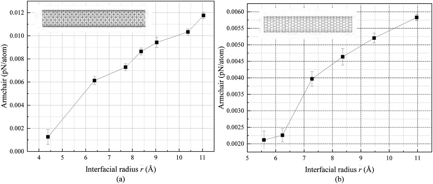 | ||
| Fig. 4 The variation in interlayer friction between commensurate DWCNTs of different chiral combination with changes in . (a) Armchair DWCNTs. (b) Zigzag DWCNTs. | ||
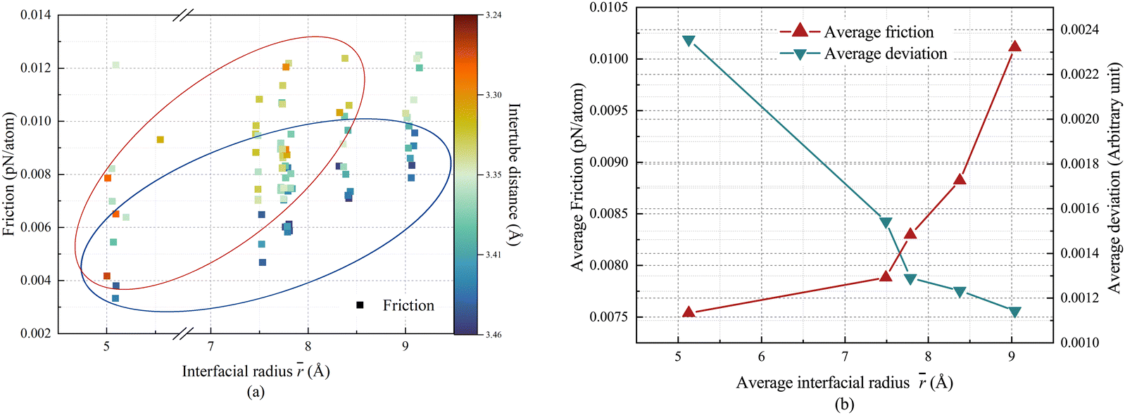
The variation pattern of interlayer friction with respect to the value under incommensurate contact conditions is illustrated in Fig. 5. As shown in Fig. 5, the interlayer friction shows an increasing trend with the increase in . Fig. 5a implies that with the increment in Δr, the influence of on interlayer friction is enhanced. However, there are still differences in interlayer friction among DWCNTs with different chiral combinations with similar . Bellarosa et al. pointed out that the mismatch angle and radius of each SWCNT alter the interlayer interactions significantly. Fig. 5b illustrates the variation in average interlayer friction and average deviation of interlayer friction with changing when Δr and Δθ are not controlled. As increases, the average deviation of interlayer friction gradually decreases. This indicates that the increase in weakens the interlayer superlubricity effect caused by Δr and Δθ. Therefore, in practical applications, for high-speed rotational DWCNT bearings, selecting DWCNTs with a smaller interfacial radius can achieve a reduction in friction, especially for commensurate DWCNTs. Additionally, for DWCNT bearings with a smaller interfacial radius, more attention should be paid to the selection of chiral combinations, as the interlayer friction sensitivity to chiral combinations is significant.
 | ||
| Fig. 5 (a) Variation in interlayer friction with of DWCNTs with different chiral combinations. (b) The variation in average interlayer friction with and the average deviation in interlayer friction. | ||
3.4. Axial strain effect
Previous research has found that axial strain can also alter the interlayer friction of CNTs like selecting the chiral combination of DWCNTs.37 A series of DWCNTs is selected for the study of strain effect whose detailed information is shown in Table 2. The Δr of DWCNTs is restricted between 7.70 Å and 7.84 Å. Based on the values, DWCNTs are divided into 3 groups: 3.28 Å to 3.34 Å, 3.36 Å to 3.37 Å, and 3.41 Å to 3.44 Å, to investigate the strain effect on DWCNTs with different Δr and Δθ.
| Chirality | Δr (Å) | Δθ(°) |
|---|---|---|
| (10,8)-(24,1) | 3.44 | 24.30 |
| (11,7)-(18,10) | 3.42 | 2.06 |
| (11,7)-(21,6) | 3.42 | 10.47 |
| (14,3)-(21,6) | 3.41 | 2.70 |
| (12,6)-(21,6) | 3.37 | 6.89 |
| (10,8)-(15,13) | 3.36 | 1.30 |
| (12,6)-(24,1) | 3.36 | 17.08 |
| (10,8)-(22,4) | 3.36 | 18.12 |
| (11,7)-(15,13) | 3.33 | 4.95 |
| (14,3)-(14,14) | 3.32 | 20.48 |
| (12,6)-(15,13) | 3.29 | 8.53 |
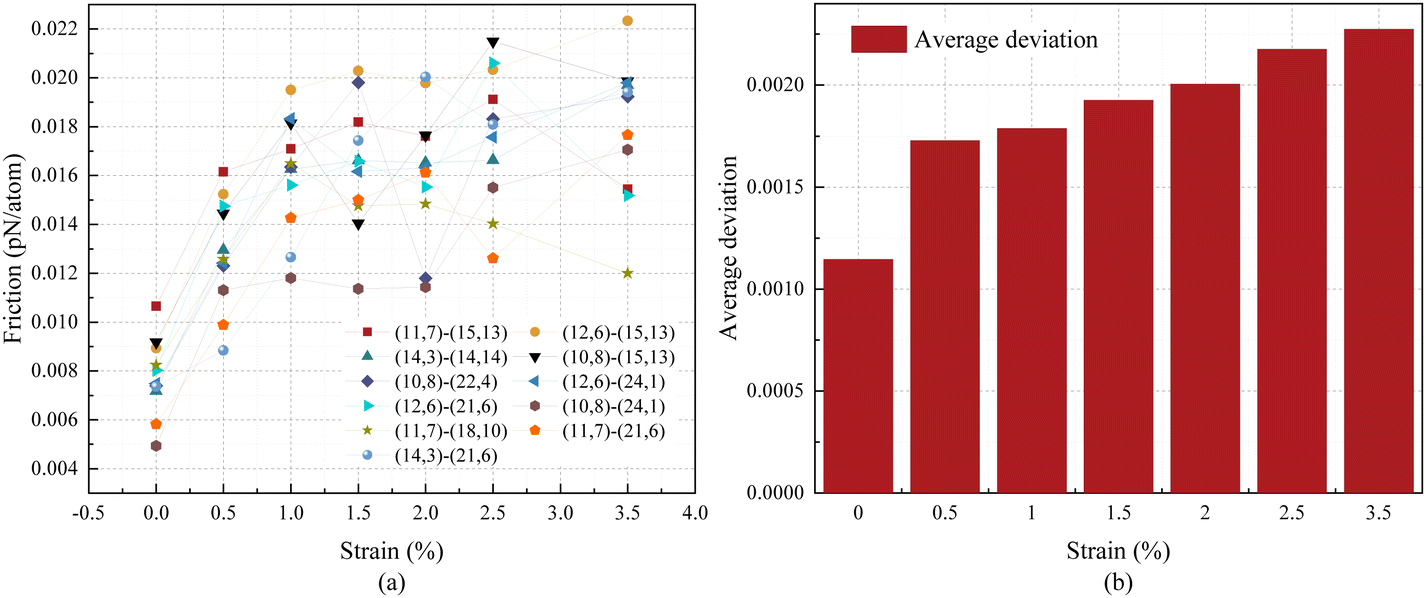
The variation in interlayer friction of DWCNTs with different chiral combinations under compression is demonstrated in Fig. 6a relatively. Obviously, with the application of compression, there is an upward trend in interlayer friction. Table 3 demonstrates the increment in interlayer friction of DWCNTs with different Δr after the application of compression. It can be found that DWCNTs with larger Δr exhibit a greater increment in interlayer friction with the application of compression. Therefore, during the high-speed rotation process of DWCNT bearings, efforts should be paid to avoid inducing compressive strain, especially for DWCNT bearings with smaller Δr. The relationship between the variation in average deviation of interlayer friction and compression is shown in Fig. 6b. With the application of compression, different chiral DWCNTs with similar values exhibit an amplification of friction differences due to the difference in Δθ. Therefore, in practical engineering, the increment of interlayer friction caused by compressive strain can be avoided by selecting the DWCNTs with a specified chiral combination.
 | ||
| Fig. 6 (a) The relationship between the variation in interlayer friction and compressive strain. (b) The average deviation of interlayer friction with changes in compressive strain. | ||
| Δr (Å) | <3.34 | 3.34–3.4 | >3.4 |
|---|---|---|---|
| Variation (%) | 114.76 | 130.10 | 150.97 |
The variation in interlayer friction of DWCNTs with different chiral combinations under tension is demonstrated in Fig. 7a. Clearly, with the application of tension there is a decreasing trend in interlayer friction. However, compared to compression the interlayer friction of DWCNTs is less sensitive to tensile strain. Table 4 presents the reduction in interlayer friction of DWCNTs with different Δr under the application of tension. It is evident that DWCNTs with larger r exhibit a greater reduction in interlayer friction with the application of tension. This implies that DWCNTs with larger Δr are more sensitive to tensile strain. As a result, application of tensile strain is an effective way to reduce energy dissipation during rotation. Especially for DWCNT bearings with larger Δr, the lubricating effect of applying tension is more pronounced. The relationship between the variation in average deviation of interlayer friction and tension is shown in Fig. 7b. Differences in friction caused by varying Δθ of DWCNTs with similar Δr are weakened by the application of tension. Comparing the lubrication effect of tensile strain (Fig. 7a) with the inter-layer friction difference of DWCNTs with different chiral combinations in this research, the difference in chiral combination brings twice the lubrication effect of tensile strain. For instance, for DWCNT chiral combinations (11,7)-(15,13), which are sensitive to tensile strain, the interlayer friction decreases by 49.76% after applying 10% tensile strain. The friction can be reduced by 68.54% through selecting chiral combinations of DWCNTs studied in this research with smaller interfacial radius, larger mismatch angle, and smaller intertube distance. Additionally, as the tensile strain increases, the lubrication effect of tensile strain gradually becomes less obvious.37 Furthermore, achieving the state of superlubricity through the selection of specific chiral combinations does not damage the structure of CNTs. However, the lubrication effectiveness of this method is not suitable for DWCNTs with specific geometric requirements, whereas the method of applying tensile strain can control the interlayer friction in real-time.
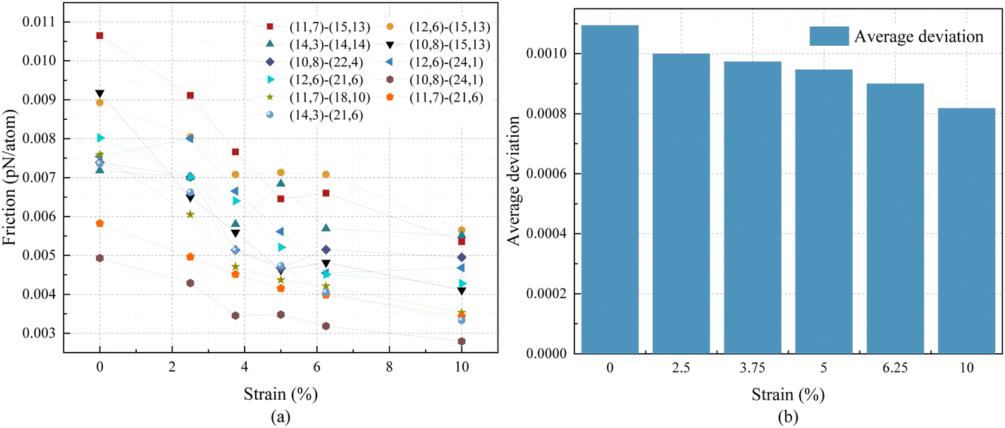 | ||
| Fig. 7 (a) The relationship between the variation in interlayer friction and tensile strain. (b) The average deviation of interlayer friction with changes in tensile strain. | ||
| Δr (Å) | <3.34 | 3.34–3.4 | >3.4 |
|---|---|---|---|
| Variation (%) | −38.30 | −34.91 | −49.10 |
3.5 Torsional strain effect
Previous studies have already demonstrated that torsional strain can alter the interlayer friction of DWCNTs in commensurate contact.38 We selected the chiral combinations of CNTs from 3.4 and classified them based on interlayer distance into three groups: 3.28 Å to 3.34 Å, 3.36 Å to 3.37 Å, and 3.40 Å to 3.44 Å, in order to investigate the variation pattern of interlayer friction with changes in torsional strain under different chiral combinations.Fig. 8 depicts the relationship between variation in interlayer friction and ϕ of DWCNTs with different Δr and various Δθ. The variation in interlayer friction with ϕ does not show a clear increasing or decreasing trend as in the case of axial strain. With the application of torsion, interlayer friction slightly increases. However, the increase in interlayer friction is not significantly correlated with the torsional strain.
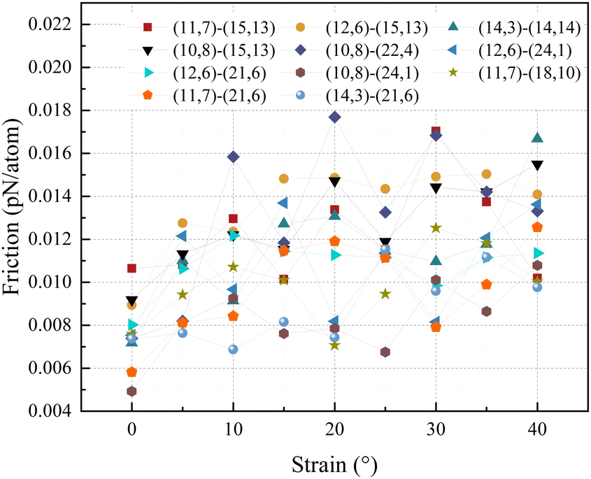 | ||
| Fig. 8 The relation between the variation of interlayer friction and the Δθ. The is set between 7.7 Å and 7.85 Å. | ||
3.6 Effect mechanism
The changes in Δr and Δθ mainly affect the interactions between carbon atoms of each SWCNT by altering the distance between carbon atoms in the inner and outer tubes. The potential energy of the interaction between two carbon atoms in the inner and outer tubes is represented using the Lennard-Jones potential energy (eqn (2)). There are differences in the impact of Δr and Δθ. The difference in the Δr directly results in variations in the distance between carbon atoms in each SWCNT, while the Δr alters the distance between carbon atoms in the tubes indirectly by changing the curvature of the CNT. Therefore, during the rotational process, DWCNTs with smaller Δr or larger interlayer spacing have higher potential energy of interlayer interactions. A larger potential barrier peak is formed on the surface of the outer tube by the inner tube. Consequently, more energy is required for the carbon atoms in the outer tube to overcome the peak of the energy barrier during rotation, resulting in greater interlayer friction. In contrast, carbon atoms in the outer tube of DWCNTs with larger Δ or smaller require less energy to overcome the potential barrier during rotation, resulting in lower interlayer friction. Different from the way Δr and impact on interlayer friction, Δθ primarily alters the trajectory of carbon atoms on the potential energy surface, which changes the energy required to overcome the potential barrier during the carbon atom rotation process. The carbon atoms in the outer tube of DWCNTs with a larger Δθ evade the potential barrier peak formed by the inner tube. Consequently, the carbon atoms in the outer tube require less energy to overcome the potential barrier during motion, resulting in lower interlayer friction. The carbon atoms in the outer tube of DWCNTs with a smaller Δθ need to overcome a higher potential barrier peak during the rotation process, resulting in greater energy dissipation and lower interlayer friction during rotational motion. Additionally, for DWCNTs with small or large , the inner tube forms a higher potential barrier peak on the surface of the outer tube. This leads to significantly higher potential barrier peaks along the motion trajectory of carbon atoms in the outer tube of DWCNTs with a smaller Δθ compared to those with larger Δθ, enhancing the lubricating effect of increasing the Δθ. When DWCNTs possess a large or small , the potential barrier peak values along the motion trajectory of carbon atoms in the outer tube of DWCNTs with different Δθ exhibit a relatively small difference. Therefore, the lubricating effect caused by increasing the Δθ is relatively less pronounced in this situation.
Existing studies indicate that CNTs exhibit a positive Poisson's ratio, and there are variations in Poisson's ratio among CNTs of different chirality.67 Therefore, the diameter of the inner tube will be changed with the application of axial strain, and the diameter of the outer tube will be changed due to the interlayer interactions, respectively. Ultimately, Δr changes under the application of axial strain. According to Fig. 9, the Δr monotonically increases under the tensile strain and monotonically decreases under the compressive strain. Additionally, for DWCNTs with larger initial Δr, the increment in is relatively larger when tension has been applied. Therefore, interlayer friction increases with the increment of compressive strain and decreases with the increment of tensile strain. As is shown in Fig. 9b, 10% tensile strain can only increase the tube spacing by about 0.005 Å. However, there is no such limitation in selecting chiral combinations of DWCNTs. The interaction between the tubes is of the van der Waals type, which shows a negative correlation with the intertube distance. Therefore, the lubricating effect of changing the chiral combination is better than applying tensile strain.
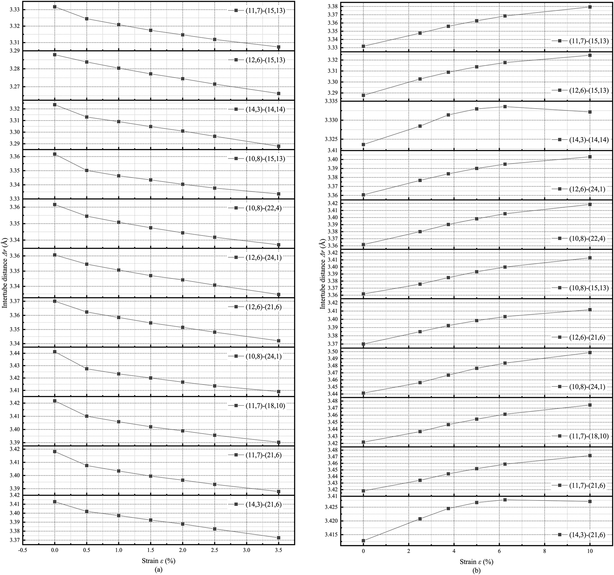 | ||
| Fig. 9 The changing of dynamic Δr under the application of axial strain. (a) Compression strain, and (b) tensile strain. | ||
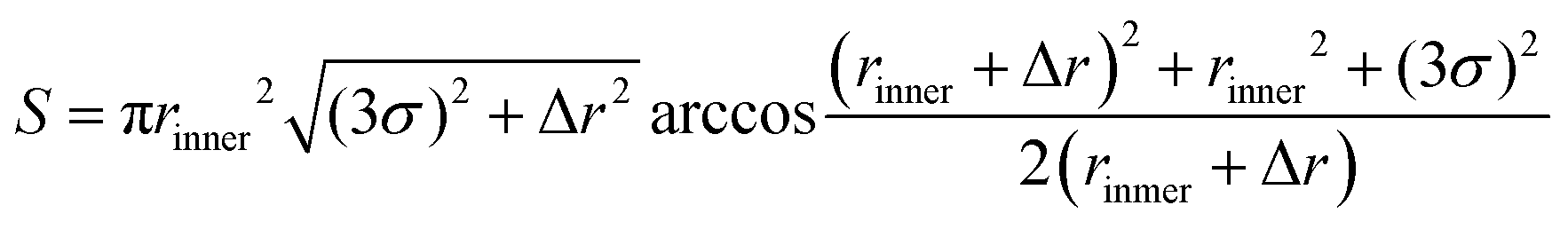
To gain a deeper understanding of the impact mechanisms of various factors on friction, a homogenized model of DWCNTs is established in this study. A qualitative analysis is conducted on the effects of and Δr on friction and its strain effects. By homogenizing the discrete carbon atom system, the surface area of the inner tube included within the range of 3σ of a carbon atom on the outer tube can be obtained:
 | (7) |
Combining the interatomic potential provided by eqn (5), the potential energy of the interaction between a single carbon atom on the outer tube and carbon atoms of the inner tube within the range of 3σ can be obtained:
 | (8) |
The A is the projection of the contained carbon atoms on the plane xOy,  is the density of carbon atoms, and a represents the length of the “C–C” bond. Therefore, with the increase of Δr and r, the potential energy of the interaction between carbon atoms decreases. The increases in r and Δr mutually inhibit their individual effects on the potential energy of interaction between each SWCNT, resulting in a mutual inhibition of their lubrication effects on each other.
Therefore, with the increase in Δr and r, the potential energy of the interaction between carbon atoms decreases. The increases in r and Δr mutually inhibit their individual effects on the potential energy of interaction between each SWCNT, resulting in a mutual inhibition of their lubrication effects on each other. ρ1 = ρ/(1 + εz)(1 − vεz), where ε represents the axial strain, and ν is the Poisson ratio of CNTs. Combining the interatomic potential provided by eqn (8), the potential energy of the interaction between a single carbon atom on the outer tube and carbon atoms of the inner tube within the range of 3σ after deformation can be obtained:
 | (9) |
Therefore, the application of strain simultaneously changes the interlayer distance, interfacial radius, and density of carbon atoms, thereby altering the potential energy of atomic interactions and ultimately affecting interlayer friction.
Unlike axial strain, torsional strain exhibits strongly coupled deformation behavior.68,69 Therefore, the mechanism of the effect of torsional strain on interlayer friction is different from axial strain. This leads to a more complex variation in frictional forces caused by applying torsional strain.
During the rotation of a DWCNT bearing with a smaller Δθ, the differences in force experienced by each carbon atom are insignificant. This allows the resistance in the motion of most carbon atoms to be superimposed. Consequently, DWCNTs with smaller Δθ exhibit higher interlayer friction. When DWCNTs exhibit a larger Δθ, the differences in force experienced by each carbon atom during the motion are obvious. The van der Waals forces acting on the carbon atoms in the CNTs cancel each other out. As a result, DWCNTs with larger Δθ exhibit lower interlayer friction.
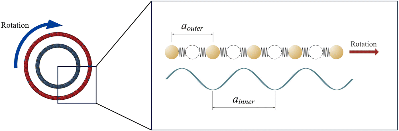
The difference in lattice periods is primarily caused by Δr and the application of strain. The connection region of DWCNTs is typically on the side of the CNTs. Due to the tubular structure of CNTs, CNTs with different radii have different circumferential lattice periods. Fig. 11 illustrates a schematic diagram of the circumferential period for the inner and outer tubes. As the inner tube has a smaller radius than the outer tube, the circumferential period of the inner tube ainner is larger than that of the outer tube aouter. Consequently, unlike the complete nesting observed in bilayer graphene, the DWCNTs cannot achieve the perfect nesting state. Additionally, with the increase in Δr, the difference in curvature between the inner and outer tubes grows, leading to an increase in circumferential period disparity and a less complete nesting of the inner and outer tubes. Therefore, in the process of high-speed pure rotation, DWCNTs with larger Δr have a higher proportion of inner tube carbon atoms located at different potential positions. This results in varied tangential forces on different atoms within the CNT. The variance of tangential forces contributes to a reduction in interlayer friction.
Previous studies have shown that when strain is applied to the CNT, its lattice structure is affected. The lattice structure after strain is depicted in Fig. 10. It can be seen that the lattice structure of the inner tube is distorted by the application of strain. The original radial and circumferential lattice periods are changed. The application of compressive strain makes the carbon atoms more compact in the axial direction, while tensile strain causes the carbon atoms to become looser in the axial direction. Additionally, as shown in Fig. 9, the application of axial strain changes the Δr of DWCNTs. It leads to a change in the difference in the interlayer circumferential period between each tube. The applied strain changes the lattice period difference by changing the distance between the atoms within the CNT.39 The difference in chiral combination, especially of mismatch angle, primarily alters the lattice period difference by modifying the directional orientation of the CNT chiral vector. Both of them can lead to the formation of the moiré pattern. The effect of the mismatch angle on the period of the moiré pattern is more direct and significant, especially close to the magic angle.70 While strain can also affect the period of the moiré pattern, the effect is usually less significant than the mismatch angle, and there is a limit to the maximum strain the CNT can withstand.71–74 The application of torsional strain is equivalent to applying uniaxial shear strain to the walls of CNTs. At this moment, the carbon atoms of CNT are staggered along the circumferential direction. As a result, in the case of different strains applied, the carbon atom is subjected to different forms of resistance during motion. The superposition of the resistance force experienced by each carbon atom also varies. Therefore, the application of strain leads to changes in interlayer friction. DWCNTs with different chiral combinations exhibit varying lattice deformations under strain. Therefore, there are differences in the strain effects on interlayer friction among DWCNTs with different chiral combinations.
 | ||
| Fig. 10 Comparison diagram of the lattice structure of SWCNT (partial) before and after the application of strain. (a) 3.5% compressive strain. (b) 10% tensile strain. (c) 40° torsional strain. | ||
 | ||
| Fig. 11 The lattice period difference between the inner and outer tubes due to the varying radius. Here, ainner represents the radial period of the inner tube, and aouter represents the radial period of the outer tube. The arrow direction indicates the direction of relative motion. | ||
 | ||
| Fig. 12 The atomic interactions of individual carbon atoms in a SWCNT include the ‘C–C’ bond interactions with neighboring carbon atoms (blue) and van der Waals interaction with other carbon atoms (yellow). The schematic diagram also illustrates the equivalent elastic support. | ||
In SWCNTs, carbon atoms are subjected to the action of both the “C–C” bond with adjacent carbon atoms and van der Waals (vdW) forces from other carbon atoms. Unlike graphene, CNTs exhibit elastic support for carbon atoms due to their curved surface. In addition to the tangential elastic support kτ, there is also normal elastic support kN, similar to the graphene-spring model.65 The radial amplitude of carbon atoms in DWCNTs with different under different strains is depicted in Fig. 13. As the of the DWCNTs increases, the surface of the SWCNTs approaches a more planar structure. This reduces the normal stiffness component arising from atomic interactions, causing an increase in the radial amplitude of atoms within the inner tube. Consequently, this leads to an increase in interlayer friction. The atomic vibration amplitude is increased by the compressive strain and reduced by the tensile strain. Similarly, the application of axial strain can also alter the atomic vibrational amplitudes within the CNT. Compressive strain intensifies the atomic vibrational amplitudes, while tensile strain weakens the amplitude of atomic vibrations. Axial strain modulates the vibrational state of the inner tube atoms, by altering the form of the thermal motion of carbon atoms. Therefore, axial strain can be applied to control the interlayer friction.
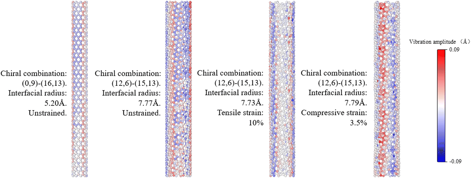 | ||
| Fig. 13 The radial amplitude of carbon atoms in the inner tube with different radius under different strain during the rotation process. The radial outward direction is defined as the positive direction. | ||
Furthermore, friction is achieved through phonon transfer during the motion between contacting layers.75,76 To gain a deeper understanding of the mechanisms behind the energy dissipation changes in different chiral DWCNTs after the application of strain, phonon spectrum analysis on rotational DWCNTs is conducted. The density of states (DOS) calculations are presented below:77
 | (10) |
 | (11) |
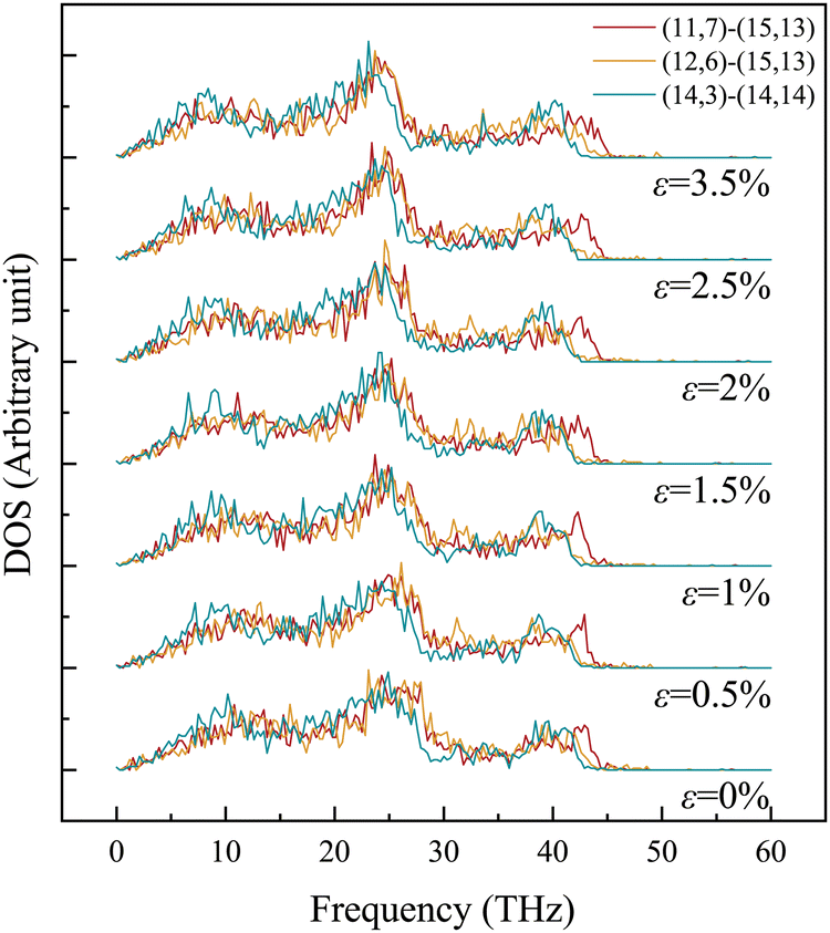 | ||
| Fig. 14 The inner tube phonon spectra of different chiral combination DWCNTs during high-speed pure rotational motion under varying axial strains. | ||
The results in the figure indicate that phonon frequencies are primarily in the range of 10 to 45 THz, with a concentration in the 20 to 30 THz range. Similar to commensurate DWCNTs and graphene friction pairs, the phonon energy distribution of the inner tube undergoes noticeable changes with the application of strain.37,79 Generally, compressive strain tends to shift the overall phonon frequencies towards higher frequencies, by increasing the range of the phonon frequency distribution and the density of high-frequency phonons. As the range of the phonon frequency distribution becomes larger, the difference in the phonon density distribution increases. As a result, the difference in the density of phonon states of different chiral DWCNTs increases gradually when compressive strain is applied. Different DWCNTs with similar Δr and different chiral combinations show gradually increasing differences in phonon density distribution with the application of compressive strain, especially in the frequency range of 20–30 THz, and differences in the concentration of high-frequency phonons. In contrast, tensile strain shifts overall phonon frequencies towards lower frequencies, accompanied by reducing high-frequency phonon density. With the application of tensile strain, the phonon density distribution of the inner tube tends to be similar. This consistency can be observed in the differences in interlayer friction during the high-speed pure rotational motion of different chiral combination DWCNTs under strain. For each DWCNT chiral combination, the variation pattern of interlayer friction with the application of axial strain is similar to the changes in the inner tube phonon spectrum with strain. That leads to the increment of the phonon frequency range.
Observing the phonon spectra under axial strain effects can provide a better understanding of the underlying mechanisms. The inner tube is directly affected by strain. Compressive strain enhances the interactions between carbon atoms, while tensile strain weakens these interactions. In general, strain alters the distribution of phonon density. Compressive strain increases the density of high-frequency phonons, accelerating the exchange of ordered kinetic energy to disordered thermal energy, thereby increasing interlayer friction. The impact of compressive strain on the phonon density varies among different chiral combinations. Similarly, tensile strain reduces phonon frequencies, resulting in a decrease in interlayer friction. The application of tensile strain concentrates phonon frequencies towards lower frequencies, causing interlayer friction to decrease with tensile strain. These results reflect the physical implications of the strain effect on frictional forces.
Conclusions and significance
The mechanism of friction in low-dimensional homogeneous thin-wall shell materials is investigated in this study. This study employed MD simulations to calculate the interlayer friction of high-speed pure rotating DWCNTs with varying interlayer distance, interfacial radius, and mismatch angle. Through a detailed analysis of the coupled effects of multiple factors, significant coupling influences of interlayer distance, mismatch angle, and interfacial radius on interlayer friction are found. In general, lower interlayer friction is observed with larger interlayer distance, greater mismatch angle, and smaller interfacial radius, with mutual interactions among these factors. Furthermore, distinct strain effects on interlayer friction are observed in different chiral combinations of DWCNTs. The effect of chiral combinations on friction is amplified by compressive strain, while tensile strain reduces the friction difference between different chiral combinations. The analysis of the phonon spectrum and homogenization model revealed that the coupling effects of chiral combination difference and strain on interlayer friction are mainly due to changes in interatomic interaction, lattice mismatch, and lattice vibration modes. These findings deepen the understanding of the coupling mechanisms behind the effects of chiral differences and strain on interlayer friction of low dimensional thin-walled structures represented by DWCNTs. This study further elucidates the tribological mechanism at the nanoscale and is expected to provide guidance for the design and application of low-dimensional thin-walled materials.Author contributions
Yi Cai: methodology, formal analysis, writing – original draft, writing – review & editing. Jianzhang Huang: conceptualization, investigation, funding acquisition, writing – review & editing. Shuang Gan: validation, writing – review & editing. Yingjing Liang: supervision, methodology, funding acquisition, writing – review & editing. Qiang Han: supervision, methodology, writing – review & editing. Kejing Wang: visualization, software.Data availability
The data that support the findings of this study are available from the corresponding author upon reasonable request.Conflicts of interest
There are no conflicts to declare.Acknowledgements
The authors wish to acknowledge the support from the National Natural Science Foundation of China (Grant No. 12102097, and 52178193), and the Natural Science Foundation of Guangdong Province (Grant No. 2020A1515010915, 2022A1515012037, and 2022A1515012086).References
- Z. J. Zheng, Z. G. Guo, W. M. Liu and J. B. Luo, Friction, 2023, 11, 1121–1137 CrossRef CAS.
- P. Kapsa, Adv. Eng. Mater., 2001, 3, 531–537 CrossRef.
- E. Broitman, Friction, 2014, 2, 40–46 CrossRef.
- W. Z. Zhai, N. Srikanth, L. B. Kong and K. Zhou, Carbon, 2017, 119, 150–171 CrossRef CAS.
- S. Sasaki, e-J. Surf. Sci. Nanotechnol., 2023, 21, 98–104 CrossRef CAS.
- J. L. Sun and S. N. Du, RSC Adv., 2019, 9, 40642–40661 RSC.
- X. C. Chen and J. J. Li, Carbon, 2020, 158, 1–23 CrossRef CAS.
- H. T. Chung, J. H. Won and P. Zelenay, Nat. Commun., 2013, 4, 1922 CrossRef.
- V. K. Gupta and T. A. Saleh, Environ. Sci. Pollut. Res., 2013, 20, 2828–2843 CrossRef CAS.
- J. Ren, L. Li, C. Chen, X. Chen, Z. Cai, L. Qiu, Y. Wang, X. Zhu and H. Peng, Adv. Mater., 2013, 25, 1155–1159 CrossRef CAS PubMed.
- A. Eatemadi, H. Daraee, H. Karimkhanloo, M. Kouhi, N. Zarghami, A. Akbarzadeh, M. Abasi, Y. Hanifehpour and S. W. Joo, Nanoscale Res. Lett., 2014, 9, 393 CrossRef.
- K. Chen, W. Gao, S. Emaminejad, D. Kiriya, H. Ota, H. Y. Y. Nyein, K. Takei and A. Javey, Adv. Mater., 2016, 28, 4397–4414 CrossRef CAS.
- J. Xu, Z. Cao, Y. Zhang, Z. Yuan, Z. Lou, X. Xu and X. Wang, Chemosphere, 2018, 195, 351–364 CrossRef CAS.
- B. Y. Zhang, R. Li and Q. Peng, Nanomaterials, 2022, 12, 3363 CrossRef CAS PubMed.
- X. K. Zhang, Y. Z. Liu and J. Y. Su, Langmuir, 2022, 38, 3530–3539 CrossRef CAS.
- K. Ahmed, S. D. Avi, M. S. Tanvir, M. M. Rahman, S. Abu, M. M. I. Sagor and O. Farrok, Transportation in Between the Earth and Space by Using Carbon Nanotubes as the Elevator Cable, 2019 5th International Conference on Advances in Electrical Engineering (ICAEE), Dhaka, Bangladesh, 2019, pp. 426–430, DOI:10.1109/ICAEE48663.2019.8975533.
- Y. Miao, Q. H. Chen, Y. G. Li, D. X. Zhuo and R. Wang, Front. Mater., 2023, 10, 1129676 CrossRef.
- R. F. Zhang, Z. Y. Ning, Y. Y. Zhang, Q. S. Zheng, Q. Chen, H. H. Xie, Q. Zhang, W. Z. Qian and F. Wei, Nat. Nanotechnol., 2013, 8, 912–916 CrossRef CAS PubMed.
- Q. S. Zheng and Z. Liu, Friction, 2014, 2, 182–192 CrossRef.
- S. W. Lee and E. E. B. Campbell, Curr. Appl. Phys., 2013, 13, 1844–1859 CrossRef.
- J. Cumings and A. Zettl, Science, 2000, 289, 602–604 CrossRef CAS PubMed.
- A. Kis, K. Jensen, S. Aloni, W. Mickelson and A. Zettl, Phys. Rev. Lett., 2006, 97, 025501 CrossRef CAS PubMed.
- X. Ye, M. X. Liu, X. D. Li and X. M. Liu, Extreme Mech. Lett., 2023, 64, 102079 CrossRef.
- A. I. Vakis, V. A. Yastrebov, J. Scheibert, L. Nicola, D. Dini, C. Minfray, A. Almqvist, M. Paggi, S. Lee, G. Limbert, J. F. Molinari, G. Anciaux, R. Aghababaei, S. E. Restrepo, A. Papangelo, A. Cammarata, P. Nicolini, C. Putignano, G. Carbone, S. Stupkiewicz, J. Lengiewicz, G. Costagliola, F. Bosia, R. Guarino, N. M. Pugno, M. H. Müser and M. Ciavarella, Tribol. Int., 2018, 125, 169–199 CrossRef.
- J. Q. He, H. J. Tang and C. L. Wang, J. Ind. Eng. Chem., 2023, 126, 1–19 CrossRef CAS.
- S. L. Zhang, W. K. Liu and R. S. Ruoff, Nano Lett., 2004, 4, 293–297 CrossRef CAS.
- A. Hossain, R. Manu and S. Shibli, Chemically Modified Carbon Nanotubes for Commercial Applications, 2023, pp. 441–461 Search PubMed.
- W. L. Guo, W. Y. Zhong, Y. T. Dai and S. A. Li, Phys. Rev. B:Condens. Matter Mater. Phys., 2005, 72, 075409 CrossRef.
- R. L. Vander Wal, K. Miyoshi, K. W. Street, A. J. Tomasek, H. Peng, Y. Liu, J. L. Margrave and V. N. Khabashesku, Wear, 2005, 259, 738–743 CrossRef CAS.
- A. N. Kolmogorov and V. H. Crespi, Phys. Rev. Lett., 2000, 85, 4727–4730 CrossRef CAS.
- C. D. Wu, T. H. Fang and F. Y. Tung, Micromachines, 2017, 8, 84 CrossRef.
- Y. A. Li, N. Hu, G. Yamamoto, Z. C. Wang, T. Hashida, H. Asanuma, C. S. Dong, T. Okabe, M. Arai and H. Fukunaga, Carbon, 2010, 48, 2934–2940 CrossRef CAS.
- Z. R. Guo, T. C. Chang, X. M. Guo and H. J. Gao, Phys. Rev. Lett., 2011, 107, 105502 CrossRef.
- R. F. Zhang, Z. Y. Ning, Z. W. Xu, Y. Y. Zhang, H. H. Xie, F. Ding, Q. Chen, Q. Zhang, W. Z. Qian, Y. Cui and F. Wei, Nano Lett., 2016, 16, 1367–1374 CrossRef CAS.
- E. H. Cook, M. J. Buehler and Z. S. Spakovszky, J. Mech. Phys. Solids, 2013, 61, 652–673 CrossRef CAS.
- Q. Z. Zhao, M. B. Nardelli and J. Bernholc, Phys. Rev. B:Condens. Matter Mater. Phys., 2002, 65, 144105 CrossRef.
- J. Huang and Q. Han, Nanot, 2018, 29, 325703 CrossRef.
- J. Huang and Q. Han, Appl. Nanosci., 2019, 9, 1–5 CrossRef.
- J. Li, Y. Peng, X. Tang, Q. Xu and L. Bai, Phys. Chem. Chem. Phys., 2021, 23, 4988–5000 RSC.
- A. M. Fennimore, T. D. Yuzvinsky, W. Q. Han, M. S. Fuhrer, J. Cumings and A. Zettl, Nature, 2003, 424, 408–410 CrossRef CAS.
- A. Barreiro, R. Rurali, E. R. Hernández, J. Moser, T. Pichler, L. Forró and A. Bachtold, Science, 2008, 320, 775–778 CrossRef CAS.
- Q. W. Hou, B. Y. Cao and Z. Y. Guo, Nanot, 2009, 20, 495503 CrossRef PubMed.
- Z. R. Guo, T. C. Chang, X. M. Guo and H. J. Gao, J. Mech. Phys. Solids, 2012, 60, 1676–1687 CrossRef CAS.
- K. Cai, J. Wan, Q. H. Qin and J. Shi, Nanot, 2016, 27, 055706 CrossRef PubMed.
- J. Z. Huang and Q. Han, Nanot, 2016, 27, 155501 CrossRef.
- M. Habibi, D. Hashemabadi and H. Safarpour, Eur. Phys. J. Plus, 2019, 134, 1–23 CrossRef.
- H. Ding, L. Chen and W. T. Huang, Ieice Electron. Exp., 2023, 20, 20230373 CrossRef.
- J. E. Omoriyekomwan, A. Tahmasebi, J. X. Dou, R. Wang and J. L. Yu, Fuel Process. Technol., 2021, 214, 106686 CrossRef CAS.
- D. Yang, L. Li, X. Li, W. Xi, Y. Zhang, Y. Liu, X. Wei, W. Zhou, F. Wei, S. Xie and H. Liu, Nat. Commun., 2023, 14, 2491 CrossRef CAS PubMed.
- Y. Li, L. Li, H. Jiang, L. Qian, M. He, D. Zhou, K. Jiang, H. Liu, X. Qin, Y. Gao, Q. Wu, X. Chi, Z. Li and J. Zhang, Sci. Adv., 2024, 10, eadn6519 CrossRef CAS.
- J. J. Su, C. B. Musgrave, Y. Song, L. B. Huang, Y. Liu, G. Li, Y. E. Xin, P. Xiong, M. M. J. Li, H. R. Wu, M. H. Zhu, H. M. Chen, J. Y. Zhang, H. C. Shen, B. Z. Tang, M. Robert, I. Goddard and R. Q. Ye, Nat. Catal., 2023, 6, 818–828 CrossRef CAS.
- J. C. Spear, B. W. Ewers and J. D. Batteas, Nano Today, 2015, 10, 301–314 CrossRef CAS.
- R. L. Wang, F. Z. Zhang, K. Yang, Y. H. Xiong, J. Tang, H. Chen, M. C. Duan, Z. J. Li, H. L. Zhang and B. Y. Xiong, Adv. Colloid Interface Sci., 2023, 321, 103004 CrossRef CAS.
- A. P. Thompson, H. M. Aktulga, R. Berger, D. S. Bolintineanu, W. M. Brown, P. S. Crozier, P. J. I. Veld, A. Kohlmeyer, S. G. Moore, T. D. Nguyen, R. Shan, M. J. Stevens, J. Tranchida, C. Trott and S. J. Plimpton, Comput. Phys. Commun., 2022, 271, 108171 CrossRef CAS.
- J. Li, T. Shi, Y. Sun, X. Cai, R. Gao, Q. Peng, P. Lu and C. Lu, Nanomaterials, 2024, 14, 1423 CrossRef CAS PubMed.
- G. Dhaliwal, P. B. Nair and C. V. Singh, Carbon, 2019, 142, 300–310 CrossRef CAS.
- C. Si, X.-D. Wang, Z. Fan, Z.-H. Feng and B.-Y. Cao, Int. J. Heat Mass Transfer, 2017, 107, 450–460 CrossRef CAS.
- A. D. Baczewski and S. D. Bond, J. Chem. Phys., 2013, 139, 044107 CrossRef.
- M. S. Dresselhaus, G. Dresselhaus and R. Saito, Carbon, 1995, 33, 883–891 CrossRef CAS.
- T. Morishita, Mol. Phys., 2010, 108, 1337–1347 CrossRef CAS.
- J. Q. Wei, B. Jiang, X. F. Zhang, H. W. Zhu and D. H. Wu, Chem. Phys. Lett., 2003, 376, 753–757 CrossRef CAS.
- M. Dienwiebel, G. S. Verhoeven, N. Pradeep, J. W. M. Frenken, J. A. Heimberg and H. W. Zandbergen, Phys. Rev. Lett., 2004, 92, 126101 CrossRef.
- U. Tartaglino, V. N. Samoilov and B. N. J. Persson, J. Phys.:Condens. Matter, 2006, 18, 4143–4160 CrossRef CAS PubMed.
- Y. M. Song, C. Y. Qu, M. Ma and Q. S. Zheng, Small, 2020, 16, 1903018 CrossRef CAS PubMed.
- H. W. Zhang, Z. R. Guo, H. Gao and T. C. Chang, Carbon, 2015, 94, 60–66 CrossRef CAS.
- H. Zhou, J. T. Leng, Z. R. Guo, J. X. Li, Z. L. Huo, J. X. Qu and T. C. Chang, J. Appl. Mech., 2019, 86, 091003 CrossRef.
- M. Canadija, Carbon, 2021, 184, 891–901 CrossRef.
- K. Chandraseker and S. Mukherjee, J Appl Mech., 2006, 73, 315–326 CrossRef CAS.
- S. Dmitrovic, T. Vukovic, Z. P. Popovic, I. Milosevic and M. Damnjanovic, J. Phys.:Condens. Matter, 2013, 25, 145301 CrossRef CAS.
- Y. Xiao, J. Liu and L. Fu, Matter, 2020, 3, 1142–1161 CrossRef.
- J. Mao, S. P. Milovanović, M. Anelković, X. Lai, Y. Cao, K. Watanabe, T. Taniguchi, L. Covaci, F. M. Peeters and A. K. Geim, et al. , Nature, 2020, 584, 215–220 CrossRef CAS PubMed.
- S. Yang, Y. Chen and C. Jiang, InfoMat, 2021, 3, 397–420 CrossRef.
- S. Liu, Y. Chen, G. Zhang and Y. Liu, Appl. Surf. Sci., 2024, 657, 159792 CrossRef CAS.
- Y. Li and B. Zhang, Phys. Chem. Chem. Phys., 2024, 26, 3548–3559 RSC.
- H. Liu, B. M. Yang, C. Wang, Y. S. Han and D. M. Liu, Friction, 2023, 11, 839–864 CrossRef.
- Y. Dong, Y. K. Wang, Z. Q. Duan, S. Y. Huang, Y. Tao, X. Lu, Y. Zhang, Y. J. Kan, Z. Y. Wei, D. Y. Li and Y. F. Chen, Friction, 2023, 11, 966–976 CrossRef.
- N. S. Scott, Comput. Phys. Commun., 2013, 184, 1348 CrossRef CAS.
- J. Liu, M. Alhashme and R. G. Yang, Carbon, 2012, 50(3), 1063–1070 CrossRef CAS.
- J. Z. Huang, S. Gan, Y. Cai, Y. J. Liu and Y. J. Liang, Nanotechnol. Rev., 2023, 12, 20230128 CrossRef CAS.
Footnote |
| † Electronic supplementary information (ESI) available. See DOI: https://doi.org/10.1039/d4cp03320e |
| This journal is © the Owner Societies 2025 |