 Open Access Article
Archerfish: a retrofitted 3D printer for high-throughput combinatorial experimentation via continuous printing†
Alexander E.
Siemenn
 *,
Basita
Das
 ,
Eunice
Aissi
,
Fang
Sheng
,
Lleyton
Elliott
,
Blake
Hudspeth
,
Marilyn
Meyers
,
James
Serdy
and
Tonio
Buonassisi
*
,
Eunice
Aissi
,
Fang
Sheng
,
Lleyton
Elliott
,
Blake
Hudspeth
,
Marilyn
Meyers
,
James
Serdy
and
Tonio
Buonassisi
*
Department of Mechanical Engineering, Massachusetts Institute of Technology, Cambridge, MA 02139, USA. E-mail: asiemenn@mit.edu; buonassisi@mit.edu
First published on 31st January 2025
Abstract
The maturation of 3D printing technology has enabled low-cost, rapid prototyping capabilities for mainstreaming accelerated product design. The materials research community has recognized this need, but no universally accepted rapid prototyping technique currently exists for material design. Toward this end, we develop Archerfish, a 3D printer retrofitted to dispense liquid with in situ mixing capabilities for performing high-throughput combinatorial printing (HTCP) of material compositions. Using this HTCP design, we demonstrate continuous printing throughputs of up to 250 unique compositions per minute, 100× faster than similar tools such as Opentrons that utilize stepwise printing with ex situ mixing. We validate the formation of these combinatorial “prototype” material gradients using hyperspectral image analysis and energy-dispersive X-ray spectroscopy. Furthermore, we describe hardware challenges to realizing reproducible, accurate, and precise composition gradients with continuous printing, including those related to precursor dispensing, mixing, and deposition. Despite these limitations, the continuous printing and low-cost design of Archerfish demonstrate promising accelerated materials screening results across a range of materials systems from nanoparticles to perovskites.
1 Introduction
Innovation of advanced materials is key for the development of next-gen technologies. Progression of technologies such as renewable energy, efficient microchips, strong and lightweight composites, flexible electronics, and non-flammable batteries hinges on the innovation of new, advanced materials.1–3 Historically, scientists have innovated advanced materials by cross-referencing existing literature and then modifying material recipes through domain expertise. In 1998, Rao4 published a study documenting their successes in the discovery of novel high-performance materials through this manual, domain expertise-driven experimental procedure across a range of systems including transition metal oxides, superconducting alloys, porous solids, and nanomaterials. However, by relying primarily on domain expertise to drive materials innovation, our exploration process is limited to the bounds of human knowledge. Instead, a structured approach of exploring the complex space of material composition, crystallinity, processing conditions, and performance becomes necessary to expand the materials innovation procedure beyond the boundaries of human expertise. The concept of a multi-stage materials workflow introduced by Hanak5 in 1970 helps develop a backbone for what this structured materials innovation procedure could look like. This structured procedure consists of the following steps: (1) synthesize many material compounds, (2) perform rapid, non-destructive chemical characterization on the compounds, (3) analyze the compound properties, and (4) acquire and process the collected chemical and property data. Today, scientists across various domains have adapted this workflow using robotics and machine learning to innovate on advanced materials.6–9Many of these advancements in accelerating the materials innovation pipeline can be attributed to the recent rise in high-throughput combinatorial printing (HTCP) methods. These HTCP methods enable both the automated and fast deposition of material compounds and have shown promise across several material domains, including lithium-ion batteries,10,11 aerosolized nanoparticles,12 carbon nanotube composites,13 and photovoltaic semiconductors.14 However, much of this HTCP hardware is often cost-prohibitive for researchers, costing tens to hundreds of thousands of U.S. dollars.8,15 Hence, there is a need for the development of low-cost HTCP methods to alleviate these cost barriers.16 Therefore, with current manufacturing and economic advancements in precision technologies such as 3D printing,17 some HTCP tools can be re-engineered using these low-cost technologies, in turn, increasing the accessibility to HTCP methods for materials experimentation applications.
In this paper, we present the design of Archerfish, an open-hardware HTCP built by retrofitting low-cost 3D printer technology with rapid in situ fluid mixing capabilities to perform continuous printing of material compositions. These materials are treated as “rapid prototypes” such that they are created rapidly and certain have properties that transfer between scales but the materials themselves are of lower fidelity and quality than the final product. Hence, the materials synthesized by Archerfish are meant to provide high-throughput experimental input for the screening of candidate materials – these prototypes do not supplement the need to produce the final candidate materials themselves.
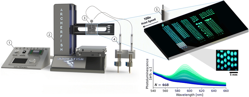
The name Archerfish derives from the tropical fish Toxotes jaculatrix, otherwise known as the archer fish for its utilization of rapidly jetting water droplets from its mouth water to strike prey from trees and branches into the water.18 Our Archerfish tool utilizes similar droplet jetting methods but to rapidly deposit arrays of material compounds onto a substrate, rather than to strike prey, where each droplet consists of a unique material composition. Fig. 1 illustrates the design and continuous printing procedure of the Archerfish HTCP system. The ultimate design objective of Archerfish is to support general and high-throughput experimentation of materials at the bench-top scale. Archerfish has been custom-built to democratize the HTCP process through the assembly of low-cost additive manufacturing technologies, such as motion control systems, microcontrollers, and precision stepper motors. Archerfish leverages these precision motor control advancements of 3D printer technology by retrofitting the printer motion axis with a combinatorial in situ fluid mixing print head and multi-syringe pump assembly, controlled by a microcontroller. Through the implementation of this simple yet robust hardware architecture, we demonstrate the deposition of up to 250 unique deposited compositions per minute, across three different material systems: (1) colored dyes, (2) metal nanoparticles, and (3) perovskite semiconductors. Further information on the build instructions, unit tests, bill of materials, and design alternatives can be found in the ESI† and on GitHub: https://github.com/PV-Lab/Archerfish.
2 Archerfish design objectives
Archerfish was developed to democratize and simplify the hardware used for high-throughput and low-volume materials experimentation across various material domains. Since its conception, Archerfish19 has been used to perform structured materials exploration experiments, including the rapid optimization of droplet morphology using machine learning20 and the rapid synthesis of semiconductors for automated characterization of band gap and stability.21 Building from these successful demonstrations of Archerfish as a tool for materials experimentation, in this paper, we aim to share its design as open-hardware for the community to use and modify for their own experimental applications. The design of Archerfish is built upon the following objectives:2.1 Maximize throughput
We design Archerfish to maximize the number of characterizable material samples generated per unit time. Maximizing sample generation enables researchers to experimentally screen through vast material state spaces quickly to identify regions of high-performing materials. This high-throughput sample generation is also generalizable to allow interchangeability between material systems, substrates, and printing form factors to maximize utility across diverse use cases. Archerfish is designed to achieve a target throughput of 250 unique samples per minute and is demonstrated to accurately generate samples across various material systems from colored dyes to metal nanoparticles to hybrid perovskite semiconductors while using different substrates and sample form factors.2.2 Minimize cost
We design Archerfish to drive down the total cost of ownership (TCO) for combinatorial experimental systems:22| TCO = I + N × S, | (1) |
3 Related work
Archerfish is designed to be a low-cost tool that enables small-volume, high-throughput printing of general materials via continuous printing paired with combinatorial in situ mixing. In this section, we give an overview of the prior art that we build Archerfish upon as well as the state-of-the art in the field. These topics include self-driving laboratories, low-cost high-throughput systems, and inkjet printing in materials research.3.1 Archerfish foundations
In this section, we highlight the foundational pieces of literature upon which Archerfish was built. Firstly, before the conception of the presented version of Archerfish in this paper, several prior iterations existed with varying designs for fluid pumping, valve placement, and mixing junctions. Through trial and error and exploration of the literature, we converged on the presented design. Prior to this convergence, several systems developed for drop-on-demand (DOD) printing of materials inspired our miniaturized combinatorial printing approach. Bash et al.13 use this DOD printing method with in situ mixing to deposit varying proportions of carbon nanotube mixtures onto a substrate for electrical characterization. Furthermore, similar DOD combinatorial printing procedures are conducted using the Opentrons overhead volumetric pipetting robot.23,24 These DOD combinatorial printing methods often employ ex situ mixing, which provides precision compositional control but significantly slower throughputs. We build upon these prior methods by implementing in situ mixing of fluid dispensed by continuous syringe pumps. In situ mixing lowers the compositional control of the printing process but significantly accelerates its throughput. Furthermore, by actuating a solenoid valve on the print head, the continuous gradient-like flow of mixed fluids is broken up into miniaturized samples that are then rapidly deposited onto a substrate. Yang et al.25 demonstrate accelerated throughputs in the deposition of metal oxide compounds using this inkjet printing process. Moreover, Collord et al.26 implement gradient-based spray coating methods to generate over 6000 unique compositions of earth-abundant kesterite semiconductors. We have culminated these concepts of combinatorial printing by Bash et al.,13 high-throughput materials inkjetting by Yang et al.,25 and gradient methods to generate massive numbers of unique compositions by Collord et al.26 to conceive the Archerfish HTCP tool.3.2 Material combinatorics
Since the inception of the structured multi-stage materials research workflow proposed by Hanak in 1970,5 similar workflows have been implemented to perform structured, combinatorial experimentation across various deposition methods, such as sputtering, inkjetting, and solution synthesis,27 and across various scientific domains, such as catalysis, electronic materials, polymers, and biomaterials.28 Recently, many material combinatorics studies have adopted methods of automated synthesis. Automated synthesis often utilizes a structured materials workflow, enabling them to perform experimentation significantly faster than conventional.6,9,29Automated synthesis methods for combinatorics can be categorized into different classes based on how the automation itself is implemented. For example, one class includes methods that automate the process of traditional synthesis, such as automated modular microfluidic platform,30–34 automated powder dosing and sintering platform to explore novel material candidates,35 and automated multi-step thin film processing.6,36–38 Another class of automated synthesis methods includes those in which one or multiple robotic arms orchestrate the motion of samples between various stations.9,35,39 Recently, a new class of automated synthesis methods for combinatorics has emerged that leverages the speed and cost advantages of sample miniaturization.40,41 Examples include aerosol-spray-based systems using dispensing robots8 and nanolithography growth techniques42 to enable high-throughput synthesis and screening of vast mega libraries of materials while utilizing low volumes of precursors. However, implementation of such robotic platforms often requires large capital investments, available to few labs or institutions. Archerfish fills this gap by offering a low-cost, sample miniaturization tool for high-throughput materials combinatorics.
3.3 Low-cost, high-throughput systems
To increase the accessibility of fast and automated materials research tools, researchers have been building low-cost devices in-house. Lo et al.16 details an array of these low-cost solutions for automated research in a comprehensive review article. Researchers have been home-building these low-cost and high-throughput systems through the integration of sensor systems, peristaltic pump liquid handling, and python-based system control.43–45 Another level for these low-cost automated tools includes the integration of motion control systems for array-like dispensing. Xie et al.46 develop a robotic platform that utilizes a 3-dimensional motion gantry system with a stepper motor syringe pump system to synthesize metal–organic materials. Archerfish embodies a similar design to that developed by Xie et al.46 but also implements a material jetting technique to further boost throughputs while maintaining miniaturized samples.3.4 Inkjet printing in materials research
Inkjet printing has emerged as the low-cost direct deposition manufacturing technique for printing a diverse array of materials.47 The conceptual simplicity, environmental friendliness, non-contact deposition onto a substrate, and material compatibility have propelled the development of such inkjet printing methods across fields.48 As a result, numerous successful implementations of material synthesis and deposition using inkjet printing have been demonstrated in application areas such as solar fuel cells,49 perovskite solar cells,50–52 oxide materials,53 quantum dots,54 nanoparticles,55 cuprate superconductors,56 and biocompatible and electroactive polymers.57 In addition to these materials-focused applications of inkjet printing, similar methods have been applied in biological engineering for DNA synthesis48 and drug discovery.58Inkjet printing for materials applications provides both cost and time savings through the miniaturization of experiments.59,60 Miniaturized experiments are low-volume and small, which saves on the cost of precursors but also enables many more discrete compositions to be synthesized per unit area. However, the speed of inkjet printing is often limited by the speed of ink formulation due to conventional systems not mixing inks in situ.8 Archerfish overcomes this limitation by combining a solenoid valve print head for diverse ink handling47 with an upstream continuous fluid dispensing system. By leveraging both the principles of sample miniaturization and in situ mixing, Archerfish is capable of performing continuous combinatorial material printing at a rate of up to 250 unique compositions per minute.
4 Continuous fluids dispensing
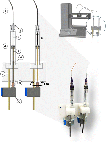
Archerfish continuously dispenses precursor fluids from two syringe pumps at variable rates to deposit gradients of material compounds as individual droplets. Fig. 2 illustrates the construction of the syringe pump assembly that drives the continuous dispensing. Unique precursor solutions are stored within the holding volume of the syringes, for example, FAPbI3 (formamidnium lead iodide) and MAPbI3 (methylammonium lead iodide), which are two different liquid formulations of hybrid organic–inorganic perovskite semiconductors.21 These precursors are differentially pumped from the syringe holding volumes through a positive displacement pressure generated by the syringe plunger. Varying the angular velocities, ω, of the stepper motors drives a linear motion, v, of the plunger within each syringe:| vin = P × ωin, | (2) |
 | (3) |
The continuous dispensing of precursors forms a gradient of materials, broken up into discrete droplets that are then annealed to evaporate the solvent. For the previous example case of depositing perovskite semiconductors, the two precursor solutions FAPbI3 and MAPbI3 will combine to form a continuous gradient of mixed cation compounds, FA1−xMAxPbI3, where x is the proportion of MA such that both MA and FA proportions sum to 1. In the following sections, we describe how this gradient is deposited along a tool path as either a continuous line segment or as discrete droplets, with each droplet consisting of a unique composition. To achieve accurate combinatorial ratios of precursors, the gradient must be tuned by modifying microcontroller parameters based on vout and the path length of the outlet pipe.
5 Combinatorial fluids mixing
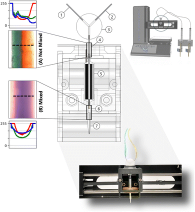
Archerfish performs in situ mixing of dispensed material precursor fluids to deposit homogeneously mixed compounds along a tool path. As the precursors flow from the syringe pump holding volume ((3) in Fig. 2) to the micro-nozzle exit ((7) in Fig. 3), they combine from two independent flows to a single flow through a Y-junction ((3) in Fig. 3). The single flow then passes through a solenoid valve ((5) in Fig. 3), which actuates at a frequency and duty cycle specified by a pulse width modulator (PWM) in the controller to break up the flow. The broken-up flow gets focused through a micro-nozzle and ejected onto a substrate placed on top of the build plate of the 3D printer. The PWM frequency and tool path speed determine whether continuous gradients or discrete droplets of material compounds are deposited. These actuation and focusing properties of the solenoid valve and nozzle are the key determiners of mixing quality in Archerfish. There is approximately 50 μL of internal volume within the plumbing of Archerfish, including the Y-junction and solenoid, and the volume of each deposited droplet varies between 1–10 μL depending on the printing parameters. Hence, there is a response latency between the input to a syringe pump and the output composition, which is calibrated to ensure that gradient mixing and deposition begin at the desired point after purging. It should be noted that droplet mixing quality is also dependent on fluid viscosity, the tendency for phase separation, and micro-nozzle geometry.5.1 Pulsation-induced mixing
Fig. 3 illustrates the print head assembly of Archerfish retrofitted with a Y-junction to combine flows, a solenoid valve to pulse and mix the flow, and a micro-nozzle to focus the flow and form discrete droplets. Pulsation-induced mixing occurs within the control volume of the solenoid valve. External pulsations or perturbations within a laminar flow are necessary to induce mixing without the use of static mixing obstacles.62,63 The Reynolds number measures the ratio of inertial to viscous forces within a flow, which determines whether the flow regime is laminar or turbulent:64 | (4) |
5.2 Vortex-induced mixing
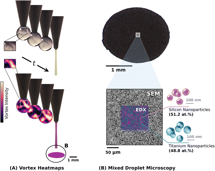
The micro-nozzle exit of the Archerfish print head is conical to constrict the fluid flow, enabling rapid jetting and break-up of the mixed fluid flows into discrete droplets with the assistance of the solenoid valve actuation. When the solenoid gate closes during actuation, fluid is rapidly displaced and jetted out from the control volume. When the solenoid gate opens, fluid flows through the control volume and surface tension forms a droplet attached to the nozzle tip.67,68 Due to the spherical shape of the droplet in this formation stage, a circulation zone forms and generates a vortex flow.66 This circulating vortex flow during the formation stage of a droplet is shown in Fig. 4A. Vortices within a droplet further drive the mixing of solutions to produce a homogeneously-mixed product.69,70 Through this flow pulsing of the solenoid valve and the flow focusing of the micro-nozzle, precursor solutions are mixed and jetted onto a substrate as unique material compositions.Fig. 4B demonstrates the mixing capabilities of Archerfish using 100 nm diameter silicon (Si) and titanium (Ti) nanoparticle suspensions, imaged by scanning electron microscopy (SEM) and energy-dispersive X-ray spectroscopy (EDX). Si and Ti nanoparticle suspensions are prepared at 5 wt%, respectively, in deionized water and ultrasonicated to form suspensions. To unit test the compositional mixing capabilities of Archerfish, these nanoparticle suspensions are loaded into the syringe pumps and dispensed by driving both pumps at equal flow rates to form droplets of equal parts silicon to titanium nanoparticles. Uniform deposition of the Si–Ti mixtures can be seen in both the SEM and EDX images after evaporating the water from the deposited droplet. An even distribution of Si nanoparticles (light regions of SEM and pink regions of EDX) and Ti nanoparticles (dark regions of SEM and blue regions of EDX) can be seen throughout the imaging field, demonstrating the mixing methods sufficiently combining and mixing the individual nanoparticle precursors. Within the EDX image field, the atomic percent contributions of each element are quantified to be 51.2 at% and 48.8 at% for Si and Ti, respectively, achieving the expected 50.0 at.%-to-50.0 at% ratio within 1.2 at% error.
6 High-throughput materials printing
6.1 Benchmarking
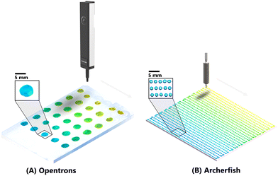
To benchmark the continuous printing performance of Archerfish, we compare its output with an Opentrons volumetric pipetting robot commonly used in automated experimental research.23,24 Opentrons utilizes stepwise printing with ex situ mixing to perform combinatorial drop-casting. Materials are printed in a stepwise fashion by mixing each set of precursor solutions, which in this demonstration are blue and yellow dyes, ex situ in an auxiliary mixing vessel such as a 96-well plate. By varying the proportions of each precursor fluid dispensed into each well of the auxiliary vessel, a gradient of materials can be mixed through orbital shaking or aspiration. Then, the mixed fluid is aspirated from the vessel and deposited via drop-casting with certain volumes onto a substrate. This ex situ mixing process is highly accurate because the exact proportions of each precursor can be precisely dispensed and mixed. In Fig. 5A, we illustrate Opentrons drop-casting a 5 × 6 gradient array onto a glass substrate. Although this ex situ mixing procedure is highly accurate, it is slow – here, a throughput of only 2.5 unique compositions per minute is achieved.Conversely, in Fig. 5B, we illustrate Archerfish continuously printing with in situ mixing, to rapidly print a 45 × 26 gradient array onto a polyester substrate. With this continuous dispensing of precursors into an in situ mixing junction, mixed through solenoid perturbation and vortices, a throughput of up to 250 unique compositions per minute is achieved, 100× faster than Opentrons stepwise printing with ex situ mixing. Although this in situ mixing process is fast, results are not as precise as ex situ mixing due to mixing quality and gradient formation becoming a function of fluid viscosity, plumbing line length and diameter, and flow velocity. In the latter sections, we quantify this error in compositional control and accuracy of in situ mixing using energy-dispersive X-ray spectroscopy. However, with proper calibration, a diverse range of material systems can be successfully printed at high-throughputs using Archerfish.
6.2 Experiments
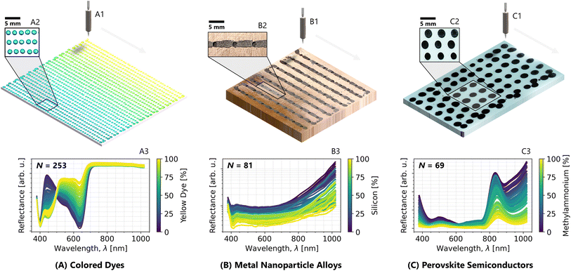
The proposed Archerfish architecture is a versatile platform with interchangeable material form factors, substrates, and printable compounds, enabling general HTCP materials experimentation. We demonstrate this generalizable nature of Archerfish by continuously printing miniaturized material samples while varying all three of these features. Form factors: (1) hundreds of small droplets closely packed, (2) continuous line segments, and (3) tens of larger droplets loosely packed. Substrates: (1) polyester sheet with a hydrophobic coating, (2) sanded copper plate with 3 mm diameter hemispherical wells, (3) glass slide. Material compounds: (1) colored dyes, (2) metal nanoparticle alloys, (3) hybrid inorganic–organic perovskite semiconductors. Fig. 6 illustrates the experimental results from these three unique printing procedures. The formation of a material gradient is illustrated using Hyperspectral imaging data from each substrate. Hyperspectral imaging validates the formation of compositional gradients across the three material systems by capturing the unique compositional signature within each material's reflectance spectrum. Here, we utilize a Resonon Pika L Hyperspectral camera with a white LED line light to capture spectral reflectance intensity information along 300 wavelength channels per pixel. Then, across all the pixels for each droplet, the average spectrum is calculated and visualized, pairing its position on the substrate to a corresponding color bar color.Fig. 6A demonstrates the close packing of many small droplets of blue-to-yellow colored dyes onto a polyester substrate. The printing throughput of Archerfish for this experiment is 250 unique compositions per minute. The continuous printing procedure trades off the ability to print singular compositions with the ability to print continuous gradients of compositions quickly. In Fig. 6(A3) we use Hyperspectral imaging to analyze the unique spectral signatures of each deposited composition and demonstrate an accurate spectral shift in composition corresponding to the programmed gradient printed from blue dye to yellow dye. As the proportion of yellow dye increases within each droplet, the blue spectral peak (400–500 nm) diminishes while the yellow spectral peak (500–600 nm) rises, validating the formation of the blue-to-yellow colored dye gradient.
Fig. 6B demonstrates the formation of line segments of titanium–silicon metal nanoparticle alloys onto a sanded copper substrate. For this experiment, 20 layers of identical gradients are printed on top of each other to form thick line segments. Prior to printing, 81 hemispherical wells are drilled into the substrate to serve as the measurement points for hyperspectral reflectance. The printing throughput of this experiment is 4 unique line segments per minute. Although the formation of a material gradient is not visually perceivable, it is detected through hyperspectral imaging. Here, we see as the proportion of silicon nanoparticles rises relative to titanium, the reflectance spectrum biases downward. The signal of this trend is noisier due to many layers of nanoparticles being imperfectly deposited on top of each other, blurring the hyperspectral signal.
Fig. 6C demonstrates the loose packing of large droplets of FAPbI3–MAPbI3 (formamidnium lead iodide–methylammonium lead iodide) organic perovskite semiconductors onto a glass substrate. The printing throughput of this experiment is 250 unique compositions per minute. Similar to the metal nanoparticles experiment, the formation of a gradient is not perceptible to the eye because most of the FAPbI3–MAPbI3 spectral shift occurs in the infrared region, detectable by hyperspectral imaging. As the proportion of methylammonium in the composition increases, the infrared peak shifts from 825 nm to 850 nm while the peak intensity decreases. These hyperspectral reflectance peaks are related to the semiconductor material property of band gap, which we further explore in a separate paper.21
Here, we demonstrate the successful printing of three different material system gradients across three different form factors at a rate of up to 100× faster than similar hardware by utilizing continuous printing and in situ mixing of the Archerfish design. Furthermore, we validate the formation of compositional gradients by analyzing the unique spectral signature of each material with hyperspectral imaging and analysis.
7 Documentation
The Archerfish system costs approximately 500 USD to build (Table 1), approximately 30× lower than the price of common commercial pipetting systems. A general bill of materials is provided in Table S-1† while a complete bill of materials, operating code repository, and design assembly of Archerfish are available on GitHub: https://github.com/PV-Lab/Archerfish. Note that many components were made in-house and require some machining and basic soldering. The reader is instructed to use the detailed design assembly provided in the GitHub repository and in the ESI† for guidance on the manufacturing and assembly of these components.| Description | Cost (USD) |
|---|---|
| Solenoid valve | 183.58 |
| 3D printer | 175.99 |
| Micro-nozzle | 50.00 |
| Arduino mega | 48.90 |
| Fittings, tubing, and pumps | 23.39 |
| PWM driver | 10.57 |
| Buttons and switches | 8.82 |
| Motors | 5.90 |
| Total | 507.15 |
8 Limitations and solutions for overcoming them
The architecture presented for high-throughput combinatorial printing with Archerfish is promising and has been used to print gradients of several different material systems.20,21 However, with its current design, Archerfish has limitations that require additional calibration time to address that can otherwise result in poor reliability and reproducibility of samples. These limitations can be categorized into three main buckets: compositional control, droplet generation, and environmental and crystallization control. Each category has unique limitation considerations for the current tool but also invites opportunities for growth and design.8.1 Lack of compositional control
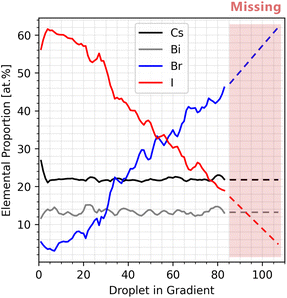
Compositional control refers to the ability to set and determine the compositions of individual droplets. With Archerfish's current architecture, it is challenging to set a specific composition for each droplet or determine a droplet's exact composition without additional measurements, such as EDX. Compositional control can be further limited by various factors but major contributors such as pressure build-ups and fluid reservoirs have been identified and are further discussed here. However, with careful calibration of the printing parameters, it is possible to control the composition of gradient printing with known endpoints that are pre-loaded as precursors in the syringes.![[small omega, Greek, dot above]](https://www.rsc.org/images/entities/i_char_e15a.gif) , in the microcontroller. When changing the substrate size or the tool path speed,
, in the microcontroller. When changing the substrate size or the tool path speed, ![[small omega, Greek, dot above]](https://www.rsc.org/images/entities/i_char_e15a.gif) must be modified to accommodate the full gradient. If the substrate size decreases in printable area,
must be modified to accommodate the full gradient. If the substrate size decreases in printable area, ![[small omega, Greek, dot above]](https://www.rsc.org/images/entities/i_char_e15a.gif) must be increased to accommodate a shorter gradient. Conversely, if the translation speed of the print head decreases to form more closely packed droplets,
must be increased to accommodate a shorter gradient. Conversely, if the translation speed of the print head decreases to form more closely packed droplets, ![[small omega, Greek, dot above]](https://www.rsc.org/images/entities/i_char_e15a.gif) must be decreased to accommodate a longer gradient. The printing speed and path are tuned by modifying the G-code parameters. G-code is a set of numerical commands used to control the linear and angular positions of stepper motors within a system.71 The G-code of Archerfish has two main tunable parameters: positional coordinates and translation speed. The generation of many closely packed droplets represents our base case for G-code parameters, which has a tool path spacing width of 3 mm along the Y-axis. To generate continuous line segments, the positional coordinates are further spaced along the Y-axis in the G-code, relative to the base case, to prevent the cohesion of independent line segments along the Y-axis. Furthermore, the tool path speed is decreased to promote the cohesion of individual droplets along the X-axis to form continuous line segments. To generate few larger, loosely packed droplets, the positional coordinates are further spaced along both the X- and Y-axes to prevent cohesion while translation speed remains the same. In general, the slower the tool path, the wider spacing required. To assist researchers in utilizing Archerfish for high-throughput materials experiments, we provide all printing parameters used for perovskite printing as open-access microcontroller code and G-code available on our GitHub repository. To solve the non-linearities due to build-up or cross-contamination, we have implemented reservoir purging processes into our open-access code. These purging processes sometimes take much longer than the prints themselves, sometimes up to a minute, and waste precursors but greatly improve the reproducibility and control of gradient compositions between runs. Further reduction of non-linearities has been implemented by replacing deformable tubing with rigid, noncompliant tubing.
must be decreased to accommodate a longer gradient. The printing speed and path are tuned by modifying the G-code parameters. G-code is a set of numerical commands used to control the linear and angular positions of stepper motors within a system.71 The G-code of Archerfish has two main tunable parameters: positional coordinates and translation speed. The generation of many closely packed droplets represents our base case for G-code parameters, which has a tool path spacing width of 3 mm along the Y-axis. To generate continuous line segments, the positional coordinates are further spaced along the Y-axis in the G-code, relative to the base case, to prevent the cohesion of independent line segments along the Y-axis. Furthermore, the tool path speed is decreased to promote the cohesion of individual droplets along the X-axis to form continuous line segments. To generate few larger, loosely packed droplets, the positional coordinates are further spaced along both the X- and Y-axes to prevent cohesion while translation speed remains the same. In general, the slower the tool path, the wider spacing required. To assist researchers in utilizing Archerfish for high-throughput materials experiments, we provide all printing parameters used for perovskite printing as open-access microcontroller code and G-code available on our GitHub repository. To solve the non-linearities due to build-up or cross-contamination, we have implemented reservoir purging processes into our open-access code. These purging processes sometimes take much longer than the prints themselves, sometimes up to a minute, and waste precursors but greatly improve the reproducibility and control of gradient compositions between runs. Further reduction of non-linearities has been implemented by replacing deformable tubing with rigid, noncompliant tubing.
8.2 Droplet generation
Archerfish can deposit gradients of uniformly thick droplets on most prints, but this uniformity can vary based on the precursor molarity and properties of the fluid or substrate. Substrates with higher wettability often distort the droplets, limit droplet packing, and add variability to their shape. Moreover, the relationship between droplet shape and the PWM driver has not been characterized in detail, making it difficult to change the droplet generation parameters along with the gradient parameters in accordance with the substrate wettability. However, by tuning the PWM parameters, it is possible to achieve target droplet geometries, which can be maintained across prints to improve reproducibility.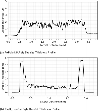 | ||
| Fig. 8 Thickness profiles of Archerfish-deposited perovskite droplets obtained using surface profilometry. (a) Organic FAPbI3–MAPbI3 perovskite droplet with 0.6 molarity. (b) Inorganic Cs3Bi2Br9–Cs3Sb2I9 (cesium bismuth bromide–cesium antimony iodide) perovskite droplet with 0.1 molarity. Different molarity droplets have varying rates of evaporation between the edge and center. The high-molarity organic-cation (MA, FA) material depositions have thicker and more even profiles on average. Conversely, the low-molarity inorganic Cs material depositions are thinner and experience species migration, accumulating material around the edge to create a coffee ring effect.72 | ||
8.3 Environmental and crystallization control
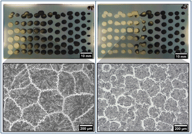
Environmental and crystallization control refers to the ability to control and create uniform crystallization conditions across all droplets on an Archerfish print. Crystallization control is not necessary for all Archerfish samples, however, some material systems cannot be studied without it. Since Archerfish is designed to be a general experimental tool, no aspect of the device is devoted to post-processing any one specific material system. For example, Archerfish does not maintain a constant temperature, pressure, or humidity around samples while or after they are printed, as these conditions would vary across different material systems.8.4 Future work
Beyond the concerns presented by a lack of compositional control, droplet generation, and environmental and crystallization control, several minor but impactful limitations warrant a mention. Many of these limitations are currently being addressed in future works.9 Conclusion
In this paper, we highlight the design and development of Archerfish, a retrofitted 3D printer for general high-throughput experimentation via continuous printing. The key design features of Archerfish include microcontroller-driven continuous dispensing of solution-based material precursors, multi-fluid mixing of laminar flows, and modular components easily installable onto existing 3D printer technology. The culmination of these design features drives rapid and continuous combinatorial deposition of materials as discrete droplets at rates of up to 250 unique compositions per minute, an acceleration factor of 100× compared to existing methods. Leveraging these accelerated printing throughputs enables the fast screening of new candidate materials as “rapid prototypes” prior to down-selection.We demonstrate this combinatorial continuous printing of Archerfish on three unique material systems, each with a different substrate and printed form factor. The three material systems span from colored dyes to metal nanoparticles to perovskite semiconductors. We analyze the unique spectral signature of each deposited material with hyperspectral imaging to validate the presence of continuous composition gradients for each material experiment. In each of these three materials experiments, a gradient is shown to exist across the printed materials through a gradual shift in the spectral reflectance. Furthermore, we highlight the limitations of the current Archerfish architecture for materials experimentation. However, despite these limitations and needs for design advancements, successful materials research has been conducted with Archerfish in the machine learning-guided optimization of droplet morphology20 and exploration of semiconductor band gaps and stabilities.21 The utilization of Archerfish as a generalizable tool for high-throughput combinatorial materials research opens the door for scientists to explore vast material spaces and rapidly test experimental hypotheses at a low cost, thereby expanding the accessibility of designing new materials across a range of applications.
Data availability
Data for this article, including EDS, hyperspectral, and profilometry data as well as the microcontroller code, comprehensive bill of materials, and complete hardware assembly file are available on GitHub at https://github.com/PV-Lab/Archerfish.Author contributions
A. E. S., J. S., and T. B. conceptualized the work. A. E. S., B. D., and T. B. designed the methodology. A. E. S., B. D., E. A., L. E., B. H., M. M., and J. S. designed and built the hardware and electronics. A. E. S., E. A., and L. E. wrote the software. A. E. S., B. D., E. A., F. S., and M. M. conducted experiments. A. E. S., B. D., and E. A. wrote the manuscript. All authors reviewed and edited the manuscript. A. E. S., B. D., and T. B. provided guidance.Conflicts of interest
There are no conflicts to declare.Acknowledgements
The authors acknowledge Shijing Sun and Liu Zhe for their discussions and input during the early development of Archerfish. A. E. S. acknowledges Nadya Peek, Lilo Pozzo, and the other participants of the “Pathways to Open-Source Hardware for Laboratory Automation” workshop, as this paper would not exist without their fruitful discussions on open hardware. The authors acknowledge Emre Tekoglu, Armi Tiihonen, Elena Botica Artalejo, and Hamide Kavak for their assistance in preparing precursors and substrates for printing. The authors acknowledge funding support from: the Defense Advanced Research Projects Agency (DARPA) under contract no. HR001118C0036; German Academic Exchange Services (DAAD); First Solar; TotalEnergies; Eni S.p.A. through the MIT Energy Initiative; University of Toronto's Acceleration Consortium; and U.S. Department of Energy's Office of Energy Efficiency and Renewable Energy (EERE) under the Solar Energy Technology Office (SETO) Award Number DE-EE0010503. This work made use of the MRSEC Shared Experimental Facilities at MIT, supported by the National Science Foundation under award number DMR-1419807.References
- S. L. Moskowitz, Advanced materials innovation: Managing global technology in the 21st century, John Wiley & Sons, 2016 Search PubMed.
- C. L. Magee, Complexity, 2012, 18, 10–25 CrossRef.
- Z. Wang, Z. Sun, H. Yin, X. Liu, J. Wang, H. Zhao, C. H. Pang, T. Wu, S. Li and Z. Yin, et al. , Adv. Mater., 2022, 34, 2104113 CrossRef CAS PubMed.
- C. Rao, J. Mater. Chem., 1999, 9, 1–14 RSC.
- J. J. Hanak, The “multiple-sample concept” in materials research: Synthesis, compositional analysis and testing of entire multicomponent systems, J. Mater. Sci., 1970, 5, 964–971 CrossRef CAS.
- B. P. MacLeod, F. G. Parlane, C. C. Rupnow, K. E. Dettelbach, M. S. Elliott, T. D. Morrissey, T. H. Haley, O. Proskurin, M. B. Rooney and N. Taherimakhsousi, et al. , Nat. Commun., 2022, 13, 995 CrossRef CAS PubMed.
- K. Hippalgaonkar, Q. Li, X. Wang, J. W. Fisher III, J. Kirkpatrick and T. Buonassisi, Nat. Rev. Mater., 2023, 8, 241–260 CrossRef.
- T. Wang, R. Li, H. Ardekani, L. Serrano-Lujan, J. Wang, M. Ramezani, R. Wilmington, M. Chauhan, R. W. Epps and K. Darabi, et al. , Matter, 2023, 6, 2963–2986 CrossRef CAS.
- A. E. Gongora, B. Xu, W. Perry, C. Okoye, P. Riley, K. G. Reyes, E. F. Morgan and K. A. Brown, Sci. Adv., 2020, 6, 1–6 Search PubMed.
- P. Liu, B. Guo, T. An, H. Fang, G. Zhu, C. Jiang and X. Jiang, J. Materiomics, 2017, 3, 202–208 CrossRef.
- I. Yanase, T. Ohtaki and M. Watanabe, Solid State Ionics, 2002, 151, 189–196 CrossRef CAS.
- M. Zeng, Y. Du, Q. Jiang, N. Kempf, C. Wei, M. V. Bimrose, A. N. Tanvir, H. Xu, J. Chen, D. J. Kirsch, J. Martin, B. C. Wyatt, T. Hayashi, M. Saeidi-Javash, H. Sakaue, B. Anasori, L. Jin, M. D. McMurtrey and Y. Zhang, Nature, 2023, 617(7960), 292–298 CrossRef CAS PubMed.
- D. Bash, Y. Cai, V. Chellappan, S. L. Wong, X. Yang, P. Kumar, J. D. Tan, A. Abutaha, J. J. Cheng, Y.-F. Lim, S. I. P. Tian, Z. Ren, F. Mekki-Berrada, W. K. Wong, J. Xie, J. Kumar, S. A. Khan, Q. Li, T. Buonassisi and K. Hippalgaonkar, Adv. Funct. Mater., 2021, 31, 2102606 CrossRef CAS.
- S. Langner, F. Häse, J. D. Perea, T. Stubhan, J. Hauch, L. M. Roch, T. Heumueller, A. Aspuru-Guzik and C. J. Brabec, Adv. Mater., 2020, 32, 1907801 CrossRef CAS PubMed.
- T. C. Wu, A. Aguilar-Granda, K. Hotta, S. A. Yazdani, R. Pollice, J. Vestfrid, H. Hao, C. Lavigne, M. Seifrid and N. Angello, et al. , Adv. Mater., 2023, 35, 2207070 CrossRef CAS PubMed.
- S. Lo, S. G. Baird, J. Schrier, B. Blaiszik, N. Carson, I. Foster, A. Aguilar-Granda, S. V. Kalinin, B. Maruyama, M. Politi, H. Tran, T. D. Sparks and A. Aspuru-Guzik, Digital Discovery, 2024, 3, 842–868 RSC.
- A. Pandian and C. Belavek, 2016 ASEE North Central Section Conference, 2016 Search PubMed.
- G. R. Allen, et al. , Record West Aust. Mus., 1978, 6, 355–378 Search PubMed.
- A. E. Siemenn, A System for High-Throughput Materials Exploration Driven by Machine Learning, 2021 Search PubMed.
- A. E. Siemenn, E. Shaulsky, M. Beveridge, T. Buonassisi, S. M. Hashmi and I. Drori, ACS Appl. Mater. Interfaces, 2022, 14, 4668–4679 CrossRef CAS PubMed.
- A. E. Siemenn, E. Aissi, F. Sheng, A. Tiihonen, H. Kavak, B. Das and T. Buonassisi, Nat. Commun., 2024, 15, 4654 CrossRef CAS PubMed.
- L. M. Ellram, Int. J. Phys. Distrib. Logist. Manag., 1995, 25, 4–23 CrossRef.
- W. Ouyang, R. W. Bowman, H. Wang, K. E. Bumke, J. T. Collins, O. Spjuth, J. Carreras-Puigvert and B. Diederich, Adv. Biol., 2022, 6, 2101063 CrossRef CAS PubMed.
- K. Potgieter and R. Meijboom, J. Chem. Technol. Biotechnol., 2021, 96, 2547–2557 CrossRef CAS.
- L. Yang, J. A. Haber, Z. Armstrong, S. J. Yang, K. Kan, L. Zhou, M. H. Richter, C. Roat, N. Wagner, M. Coram, M. Berndl, P. Riley and J. M. Gregoire, Proc. Natl. Acad. Sci. U. S. A., 2021, 118, e2106042118 CrossRef CAS PubMed.
- A. D. Collord, H. Xin and H. W. Hillhouse, IEEE J. Photovoltaics, 2015, 5, 288–298 Search PubMed.
- J. M. Gregoire, L. Zhou and J. A. Haber, Nat. Synth., 2023, 2, 493–504 CrossRef CAS.
- R. Potyrailo, K. Rajan, K. Stoewe, I. Takeuchi, B. Chisholm and H. Lam, ACS Comb. Sci., 2011, 13, 579–633 CrossRef CAS PubMed.
- M. Abolhasani and E. Kumacheva, Nat. Synth., 2023, 2, 483–492 CrossRef CAS.
- R. W. Epps, K. C. Felton, C. W. Coley and M. Abolhasani, Lab Chip, 2017, 17, 4040–4047 RSC.
- T. S. Kaminski and P. Garstecki, Chem. Soc. Rev., 2017, 46, 6210–6226 RSC.
- A. Slattery, Z. Wen, P. Tenblad, J. Sanjosé-Orduna, D. Pintossi, T. den Hartog and T. Noël, Science, 2024, 383, eadj1817 CrossRef CAS PubMed.
- A. Charalampidou, T. Nehls, C. Meyners, S. Gandhesiri, S. Pomplun, B. L. Pentelute, F. Lermyte and F. Hausch, ACS Cent. Sci., 2024, 10, 649–657 CrossRef CAS PubMed.
- J. Li, Y. Tu, R. Liu, Y. Lu and X. Zhu, Adv. Sc., 2020, 7, 1901957 CrossRef CAS PubMed.
- N. J. Szymanski, B. Rendy, Y. Fei, R. E. Kumar, T. He, D. Milsted, M. J. McDermott, M. Gallant, E. D. Cubuk, A. Merchant, H. Kim, A. Jain, C. J. Bartel, K. Persson, Y. Zeng and G. Ceder, Nature, 2023, 624, 86–91 CrossRef CAS PubMed.
- S. B. Harris, A. Biswas, S. J. Yun, K. M. Roccapriore, C. M. Rouleau, A. A. Puretzky, R. K. Vasudevan, D. B. Geohegan and K. Xiao, Small Methods, 2024, 2301763 CrossRef CAS PubMed.
- J. Wagner, C. G. Berger, X. Du, T. Stubhan, J. A. Hauch and C. J. Brabec, J. Mater. Sci., 2021, 56, 16422–16446 CrossRef CAS.
- J. Zhang, J. A. Hauch and C. J. Brabec, Acc. Chem. Res., 2024, 57, 1434–1445 CrossRef CAS PubMed.
- P. Shiri, V. Lai, T. Zepel, D. Griffin, J. Reifman, S. Clark, S. Grunert, L. P. Yunker, S. Steiner, H. Situ, F. Yang, P. L. Prieto and J. E. Hein, iScience, 2021, 24, 102176 CrossRef CAS PubMed.
- J. Schrier and A. J. Norquist, Methods and Applications of Autonomous Experimentation, Chapman and Hall/CRC, 2023 Search PubMed.
- J. Schrier, A. J. Norquist, T. Buonassisi and J. Brgoch, J. Am. Chem. Soc., 2023, 145, 21699–21716 CrossRef CAS PubMed.
- E. J. Kluender, J. L. Hedrick, K. A. Brown, R. Rao, B. Meckes, J. S. Du, L. M. Moreau, B. Maruyama and C. A. Mirkin, Proc. Natl. Acad. Sci. U. S. A., 2019, 116, 40–45 CrossRef CAS PubMed.
- D. Caramelli, D. Salley, A. Henson, G. A. Camarasa, S. Sharabi, G. Keenan and L. Cronin, Nat. Commun., 2018, 9, 3406 CrossRef PubMed.
- M. A. Flores-Ortiz, R. A. Gutiérrez-Márquez, R. S. Mier-Jiménez, M. M. Flores-Leonar and A. Aguilar Granda, Building C-C bonds using a cheap automated synthesis platform, ChemRxiv, 2023, preprint, DOI:10.26434/chemrxiv-2023-x0l8f.
- M. Politi, F. Baum, K. Vaddi, E. Antonio, J. Vasquez, B. P. Bishop, N. Peek, V. C. Holmberg and L. D. Pozzo, Digital Discovery, 2023, 2, 1042–1057 RSC.
- Y. Xie, C. Zhang, H. Deng, B. Zheng, J.-W. Su, K. Shutt and J. Lin, ACS Appl. Mater. Interfaces, 2021, 13, 53485–53491 CrossRef CAS PubMed.
- M. A. Shah, D.-G. Lee, B.-Y. Lee and S. Hur, IEEE Access, 2021, 9, 140079–140102 Search PubMed.
- X. Deng, H. Li and Y. Song, Giant, 2024, 17, 100222 CrossRef CAS.
- D. Guevarra, A. Shinde, S. K. Suram, I. D. Sharp, F. M. Toma, J. A. Haber and J. M. Gregoire, Energy Environ. Sci., 2016, 9, 565–580 RSC.
- F. Mathies, E. J. W. List-Kratochvil and E. L. Unger, Energy Technol., 2020, 8, 1900991 CrossRef CAS.
- S. Chen, L. Zhang, L. Yan, X. Xiang, X. Zhao, S. Yang and B. Xu, Adv. Funct. Mater., 2019, 29, 1905487 CrossRef CAS.
- Y. Cheng, H. Wu, J. Ma, P. Li, Z. Gu, S. Zang, L. Han, Y. Zhang and Y. Song, CCS Chem., 2022, 4, 1465–1485 CrossRef CAS.
- L. Yang, J. A. Haber, Z. Armstrong, S. J. Yang, K. Kan, L. Zhou, M. H. Richter, C. Roat, N. Wagner and M. Coram, et al. , Proc. Natl. Acad. Sci. U. S. A., 2021, 118, e2106042118 CrossRef CAS PubMed.
- L. Shi, L. Meng, F. Jiang, Y. Ge, F. Li, X.-g. Wu and H. Zhong, Adv. Funct. Mater., 2019, 29, 1903648 CrossRef.
- I. D. Styliari, C. Conte, A. K. Pearce, A. Hüsler, R. J. Cavanagh, M. J. Limo, D. Gordhan, A. Nieto-Orellana, J. Suksiriworapong, B. Couturaud, P. Williams, A. L. Hook, M. R. Alexander, M. C. Garnett, C. Alexander, J. C. Burley and V. Taresco, Macromol. Mater. Eng., 2018, 303, 1800146 CrossRef.
- A. Queraltó, J. Banchewski, A. Pacheco, K. Gupta, L. Saltarelli, D. Garcia, N. Alcalde, C. Mocuta, S. Ricart, F. Pino, X. Obradors and T. Puig, ACS Appl. Mater. Interfaces, 2021, 13, 9101–9112 CrossRef PubMed.
- A. L. Roy, H. N. Chiu and K. Walus, Lab Chip, 2021, 21, 4427–4436 RSC.
- S. E. Evans, T. Harrington, M. C. Rodriguez Rivero, E. Rognin, T. Tuladhar and R. Daly, Int. J. Pharm., 2021, 599, 120443 CrossRef CAS PubMed.
- I. D. Styliari, C. Conte, A. K. Pearce, A. Hüsler, R. J. Cavanagh, M. J. Limo, D. Gordhan, A. Nieto-Orellana, J. Suksiriworapong and B. Couturaud, et al. , Macromol. Mater. Eng., 2018, 303, 1800146 CrossRef.
- C.-C. Huang, Z.-K. Kao and Y.-C. Liao, ACS Appl. Mater. Interfaces, 2013, 5, 12954–12959 CrossRef CAS PubMed.
- D. Bernoulli, Hydrodynamica, Apud Johannem Reinholdum Dulseckern, 1738 Search PubMed.
- K. Ward and Z. H. Fan, J. Micromech. Microeng., 2015, 25, 1–15 CrossRef PubMed.
- P. R. Fortes, M. A. Feres, M. K. Sasaki, E. R. Alves, E. A. Zagatto, J. A. Prior, J. L. Santos and J. L. Lima, Talanta, 2009, 79, 978–983 CrossRef CAS PubMed.
- O. Reynolds, Philos. Trans. R. Soc. London, 1883, 174, 935–982 CrossRef.
- N. Ryan and M. Johnson, AIChE J., 1959, 5, 433–435 CrossRef CAS.
- S. A. Vagner, S. A. Patlazhan, C. A. Serra and D. Funfschilling, Phys. Fluids, 2021, 33, 072010 CrossRef CAS.
- P. Lin, Q. Chen, Y. Liu, X. Hu and Z. Zhu, ACS Omega, 2022, 7, 23890–23898 CrossRef CAS PubMed.
- K. Mutschler, S. Dwivedi, S. Kartmann, S. Bammesberger, P. Koltay, R. Zengerle and L. Tanguy, Mechatronics, 2014, 24, 209–221 CrossRef.
- M. B. Mbanjwa, K. Harding and I. M. Gledhill, Micromachines, 2022, 13, 708 CrossRef PubMed.
- A. Tiribocchi, A. Montessori, M. Lauricella, F. Bonaccorso, S. Succi, S. Aime, M. Milani and D. A. Weitz, Nat. Commun., 2021, 12(1), 1–10 CrossRef PubMed.
- A. C. Brown and D. De Beer, 2013 Africon, 2013, pp. 1–5 Search PubMed.
- R. Sliz, J. Czajkowski and T. Fabritius, Langmuir, 2020, 36, 9562–9570 CrossRef CAS PubMed.
Footnote |
| † Electronic supplementary information (ESI) available. See DOI: https://doi.org/10.1039/d4dd00249k |
| This journal is © The Royal Society of Chemistry 2025 |

