Suppressed non-radiative loss and efficient hole transfer at a small highest occupied molecular orbital offset endows binary organic solar cells with 19.73% efficiency and a small efficiency-cost gap†
Received
8th July 2024
, Accepted 13th November 2024
First published on 15th November 2024
Abstract
Suppressing energy/voltage loss and realizing efficient charge transfer at small frontier molecular orbital offsets between the donor and acceptor is viable to simultaneously improve the open-circuit voltage (Voc) and short-circuit current (Jsc), and thus the power conversion efficiency (PCE) of organic solar cells (OSCs). Here, two A–DA′D–A type acceptors, PEH-F and TEH-F, are designed and synthesized with different conjugated outer side chains, to pursue high-efficiency and cost-effective OSCs for industrialization. In comparison with TEH-F (thienyl outer side chain), PEH-F with phenyl outer side chains delivers up-shifted frontier energy levels, a wider optical bandgap, and a higher absorption coefficient. By adopting low-cost polymer PTQ11 as a donor, the PEH-F-based device realizes a low energy loss of 0.511 eV with a suppressed non-radiative loss of only 0.182 eV and exhibits efficient exciton dissociation and hole transfer even at an extremely small highest occupied molecular orbital offset of 0.06 eV. Eventually, the PTQ11:PEH-F-based binary device demonstrates a superior PCE of 19.73% with high Voc and Jsc simultaneously, which is the highest PCE to date for OSCs based on low-cost polymer donors. More importantly, this device shows a small efficiency-cost gap for industrialization with the estimated minimum sustainable price (MSP) of 0.35 $ per Wp, which is dramatically lower than those of other reported high-performance OSCs.
Broader context
Organic solar cells (OSCs) are a promising next-generation photovoltaic technology due to the advantages of solution processability, light weight, and promise in manufacturing large-scale flexible devices. However, most of the reported high-performance OSCs are based on wide bandgap conjugated polymer donors with complex chemical structures, tedious multi-step synthesis, multiple purifications, and low total synthetic yields. Therefore, it is urgent to focus on those low-cost polymer donors to realize a “win–win” situation of material cost and photovoltaic performance of OSCs for industrialization. Herein, two novel A–DA′D–A type small molecule acceptors (SMAs) with different conjugated outer side chains are designed and synthesized to explore the potential of the low-cost polymer donor PTQ11 and pursue the small efficiency-cost gap OSCs for industrialization. Eventually, the OSCs based on PTQ11 and PEH-F realize the highest efficiency of OSCs based on the low-cost polymers and the lowest estimated minimum sustainable price so far, implying that the PTQ11:PEH-F binary system is a promising candidate with a small efficiency-cost gap for industrial organic photovoltaics. Overall, the methodology for calculating the cost of solar modules and the superior results delivered by this work will provide important insights into the process of development and commercialization in the field of organic photovoltaics.
|
Introduction
Organic solar cells (OSCs), with a blend photoactive layer of a p-type conjugated polymer as a donor and an n-type organic semiconductor as an acceptor, have attracted great attention in the past several decades owing to their unique features such as low-cost fabrication by solution processing, mechanical flexibility, light weight, and large-scale applications.1–8 Due to the significant innovations in efficient photovoltaic materials,9–17 interface buffer layer materials,18–21 and device engineering,22–25 especially the invention of A–DA′D–A type small molecule acceptors (SMAs),13–15,26 the power conversion efficiency (PCE) of the state-of-the-art single-junction OSCs has reached over 19%, satisfying the requirement of photovoltaic performance for industrialization.
Nowadays, most of the reported high-performance OSCs are based on wide bandgap conjugated polymer donors, such as PM6,9 D18,11 D18-Cl,12etc., which exhibit excellent photovoltaic properties. However, due to the complex chemical structures, tedious multi-step synthesis, multiple purifications, and low total synthetic yields, the costs of those polymer donors are too high to enable large-scale preparation and industrial applications.27,28 Therefore, it is urgent to focus on those low-cost polymer donors to realize a “win–win” situation of material cost and photovoltaic performance of OSCs for industrialization. PTQ10,10 a classic low-cost polymer donor, possesses a simple molecular structure, low energy disorder, and a great uniform vertical phase distribution, as well as benefiting from the developments of A–DA′D–A type SMAs, thus enabling PTQ10-based single-junction OSCs to achieve outstanding PCEs exceeding 19%.29,30 However, the PCEs of OSCs based on another low-cost polymer donor PTQ11 (see Fig. 1a, a derivative of PTQ10 with a methyl substituent on its quinoxaline unit) have so far remained around 16%, despite the fact that PTQ11 has stronger molecular crystallinity and better charge transport capability than PTQ10.31 Therefore, there is great potential for PTQ11 that has not yet been explored.
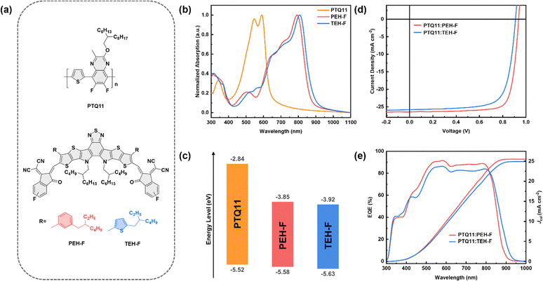 |
| | Fig. 1 (a) Molecular structures of the polymer donor PTQ11, and two SMAs, PEH-F and TEH-F. (b) Normalized UV-vis absorption spectra of the donor and SMA films. (c) Energy level diagram of the donor and SMAs. (d) J–V curves of the optimized OSCs based on PTQ11:SMA under the illumination of AM 1.5G, 100 mW cm−2. (e) EQE spectra of the corresponding optimized OSCs. | |
On the other hand, the high voltage/energy loss (Vloss/Eloss) of OSCs resulting from the small dielectric constant and large exciton binding energy of organic photovoltaic materials is the key issue that leads to their current PCEs dramatically lower than that of inorganic and perovskite solar cells.32–35 For the classical OSCs with a blended donor and acceptor photoactive layer, the feasible strategy to increase the open-circuit voltage (Voc) and reduce the Vloss/Eloss is to up-shift the lowest unoccupied molecular orbital (LUMO) energy level (ELUMO) of the acceptor or/and down-shift the highest occupied molecular orbital (HOMO) energy level (EHOMO) of the donor, and thus broadening the frontier orbital energy offset (ΔELUMO(A)–HOMO(D)).36–38 However, enlarging the ΔELUMO(A)–HOMO(D) will certainly bring about a decrease in ΔEHOMO(D–A) or/and ΔELUMO(D–A), which in turn leads to a reduced driving force for the exciton dissociation and charge transfer (CT), thus resulting in the restricted charge generation and the limited photogenerated current in OSCs.39,40 Therefore, fine tuning the molecular structure of organic photovoltaic materials to realize effective exciton dissociation and CT at low Vloss/Eloss, to maximize the open-circuit voltage (Voc) and short-circuit current density (Jsc) of the devices simultaneously, is crucial to further improve the PCE of OSCs.
On the basis of previous works, it seems that the PTQ derivative donors prefer to match with the A–DA′D–A type SMAs with bulky conjugated outer side chains for high-performance OSCs.29,30,41–44 Hence, we designed and synthesized two novel A–DA′D–A type SMAs with different conjugated outer side chains in this work, namely PEH-F and TEH-F (their molecular structures are shown in Fig. 1a), to explore the potential of low-cost polymer donor PTQ11 and pursue the small efficiency-cost gap OSCs for industrialization. Eventually, benefiting from a low Eloss of 0.511 eV with a suppressed non-radiative loss of only 0.182 eV, and efficient exciton dissociation and hole transfer processes even at an extremely small ΔEHOMO(D–A) of 0.06 eV, the PTQ11:PEH-F-based binary device achieves a remarkable PCE of 19.73% with a high Voc of 0.936 V and a large Jsc of 26.53 mA cm−2 simultaneously. To the best of our knowledge, 19.73% is the highest PCE ever achieved for OSCs based on low-cost polymer donors. More importantly, the PTQ11:PEH-F-based device shows a small efficiency-cost gap for industrialization with the estimated minimum sustainable price (MSP) of only 0.35 $ per Wp, which is dramatically lower than those of other reported high-performance OSCs. These results imply that the PTQ11:PEH-F binary system is a promising candidate with a small efficiency-cost gap for large-area fabrication and industrial applications of OSCs.
Results and discussion
Molecular synthesis and characterization
Fig. 1a shows the molecular structures of the polymer donor PTQ11 and two SMAs PEH-F and TEH-F, and the detailed synthetic routes of the two SMAs are depicted in Scheme S1 and S2 in the ESI.† It is worth noting that the monofluorine-substituted end group is used for constructing the two SMAs instead of the most widely used bifluorine-substituted end group because of its lower cost and weaker electron-withdrawing property to realize higher ELUMO of the two SMAs for achieving higher Voc in the devices. Based on the synthetic process and isolation/purification process in combination with the dosage and price of raw compounds, intermediates, reagents, synthetic yield of each chemical reaction, and the isolation/purification operations (a more detailed description as depicted in the “Cost feasibility of organic photovoltaic materials” section of the ESI†), the cost-per-kilogram (Ckg) is calculated to be 234.74 × 10³ $ per kg and 234.72 × 10³ $ per kg for PEH-F and TEH-F, respectively, lower than that of their analogues m-PEH (264.46 × 10³ $ per kg) and o-TEH (264.44 × 10³ $ per kg) with bifluorine-substituted end groups reported in our previous work (the specific calculations are summarized in Tables S1–S4 and S14, ESI†).29,42 The number average molecular weight (Mn) of PTQ11 was measured to be 47.3 kDa with an appropriate polydispersity index (PDI) of 2.51 by high-temperature gel-permeation chromatography (GPC), as shown in Fig. S1 in the ESI.† PTQ11 and the two SMAs all exhibit good thermal stability with the thermal decomposition temperature (Td) at 5% weight loss of 380 °C for PTQ11, 311 °C for PEH-F, and 314 °C for TEH-F, respectively (as illustrated in Fig. S2, ESI†), which are high enough for application as photovoltaic materials in OSCs. Fig. 1b and Fig. S3b (ESI†) display the normalized ultraviolet-visible (UV-vis) absorption spectra of PTQ11, PEH-F, and TEH-F in thin films, and Fig. S3a (ESI†) shows the absorption spectra of PTQ11:PEH-F and PTQ11:TEH-F blends in chloroform solutions and thin films. The corresponding optical data of the two SMAs are summarized in Table 1. PEH-F and TEH-F films show similar absorption profiles ranging from 300 to 1000 nm, and their maximum absorption peaks are located at 793 and 808 nm with absorption coefficients of 1.26 × 10⁵ and 1.09 × 105 cm−1, respectively. Compared with PEH-F, the TEH-F film exhibits a red-shifted and broadened absorption profile, which may be related to their molecular geometry and aggregation properties. The optical bandgap (Egopt) of TEH-F was measured and found to be 1.40 eV, slightly narrower than that of PEH-F (1.42 eV). Since the absorption region of the PTQ11 film is mainly located in the range of 400 to 700 nm, both SMAs show complementary absorption with PTQ11 in the visible to infrared region, which could potentially provide wide and efficient absorption to obtain higher Jsc in the devices.
Table 1 The physicochemical properties of PEH-F and TEH-F
| Acceptor |
λ
max, film (nm) |
λ
onset, film (nm) |
ε
film (105 cm−1) |
E
g
opt![[thin space (1/6-em)]](https://www.rsc.org/images/entities/char_2009.gif) (eV)
(eV) |
E
HOMO/ELUMOb (eV) |
|
Calculated from the onset of absorption of thin films: Egopt = 1240/λonset.
Calculated from the onset of reduction/oxidation potentials.
|
| PEH-F |
793 |
873 |
1.26 |
1.42 |
−5.58/−3.85 |
| TEH-F |
808 |
888 |
1.09 |
1.40 |
−5.63/−3.92 |
The electronic energy levels of PTQ11, PEH-F, and TEH-F are determined by cyclic voltammetry (CV) measurement based on their redox potentials (Fig. S4, ESI†). Then the EHOMO/ELUMO values of PTQ11, PEH-F, and TEH-F are calculated to be −5.52/−2.84 eV, −5.58/−3.85 eV, and −5.63/−3.92 eV, respectively (as shown in Table 1 and Fig. 1c). Since the Voc values of OSCs depend on the difference between the ELUMO(A) and the EHOMO(D), the up-shifted ELUMO of PEH-F could contribute to a higher Voc in OSCs than that of TEH-F-based device. However, achieving efficient exciton dissociation and hole transfer may be a huge challenge in the PTQ11:PEH-F blend due to its extremely small ΔEHOMO(D–A) of only 0.06 eV between the donor PTQ11 and the acceptor PEH-F.
Photovoltaic performances
In order to assess the photovoltaic performance of PEH-F and TEH-F, OSCs are fabricated with PTQ11 as a donor and with a conventional device structure of ITO/2PACz/PTQ11:SMA/PFN-Br/Ag. Fig. 1d shows the current density–voltage (J–V) characteristics of the optimized OSCs, and Table 2 lists the detailed photovoltaic performance parameters for a clear comparison. In addition, box plots and normal distribution curves for each performance parameter from sixteen individual devices based on PTQ11:PEH-F or PTQ11:TEH-F are illustrated in Fig. S5 (ESI†), respectively. As mentioned above, there is usually a competition between high Voc and high Jsc in OSCs, that is, achieving both high Voc and Jsc in OSCs is a huge challenge. However, the PTQ11:PEH-F-based device realizes a high Voc of 0.936 V and a large Jsc of 26.53 mA cm−2 simultaneously, coupled with a high fill factor (FF) of 79.45%, ultimately resulting in a superior PCE of 19.73%, which indicates that the device could successfully deliver low Vloss/Eloss, effective exciton dissociation and CT at the same time. As far as we know, 19.73% is the highest PCE reported to date for OSCs based on low-cost polymers. In contrast, the OSCs based on PTQ11:TEH-F demonstrate a poor PCE of 17.40%, with a Voc of 0.909 V, a Jsc of 25.85 mA cm−2, and a FF of 74.05%. Fig. 1e displays the external quantum efficiency (EQE) spectra of the optimal OSCs, and Fig. S6 (ESI†) shows the EQE spectra of five individual devices based on PTQ11:PEH-F or PTQ11:TEH-F, respectively. In the wavelength range of 450 nm to 850 nm, the OSC based on PTQ11:PEH-F displays a much stronger photo-to-electron response and therefore achieves a higher calculated Jsc (Jcal) value (25.52 mA cm−2) than that (24.92 mA cm−2) of the PTQ11:TEH-F-based device, which agrees quite well with the trend of J–V characteristics within 4% mismatch.
Table 2 Photovoltaic performance parameters of the optimal OSCs based on PTQ11:SMA, under the illumination of AM 1.5G (100 mW cm−2)
| Active layer |
V
oc
(V) |
J
sc
(mA cm−2) |
FFa (%) |
PCEa (%) |
|
The statistical values in the brackets are obtained from sixteen different devices.
|
| PTQ11:PEH-F |
0.936 (0.933 ± 0.003) |
26.53 (26.67 ± 0.19) |
79.45 (78.78 ± 0.36) |
19.73 (19.60 ± 0.15) |
| PTQ11:TEH-F |
0.909 (0.908 ± 0.003) |
25.85 (25.67 ± 0.20) |
74.05 (73.71 ± 0.58) |
17.40 (17.19 ± 0.16) |
Voltage/energy loss analysis
How to suppress Vloss/Eloss and thus maximize Voc by rational molecular design is the key point of achieving high-performance OSCs but still confronts a great challenge.35,36,40 According to the J–V photovoltaic performance parameters, both PTQ11:PEH-F and PTQ11:TEH-F systems exhibit a high Voc of over 0.9 V. Firstly, it could be related to the up-shifted ELUMO of two acceptors caused by the utilization of the monofluorine-substituted terminal groups with a relatively weaker electron-withdrawing feature. Moreover, we considered that the more profound reason may be attributed to the low Vloss/Eloss of the two systems. Therefore, to gain further insight into the high Voc obtained in PEH-F/TEH-F systems, the Vloss/Eloss details in both devices have been measured (the corresponding results are summarized in Fig. 2, Fig. S7 and Table S16, ESI†). Based on the Shockley–Queisser (SQ) limit, the Vloss/Eloss in OSCs can be divided into three parts (Fig. 2a), as shown in the following equation (eqn (1)):45| | | Eloss = qVloss = Eg − qVoc = (Eg − qVSQoc) + (qVSQoc − qVradoc) + (qVradoc − qVoc) = (Eg − qVSQoc) + qΔVrad,belowgapoc + qΔVnon-radoc = ΔE1 + ΔE2 + ΔE3 | (1) |
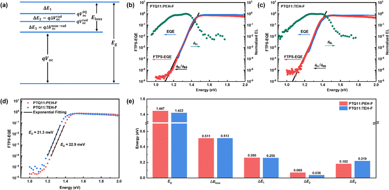 |
| | Fig. 2 (a) Schematic diagram for Vloss/Eloss of OSCs according to the SQ limit. Semilogarithmic plots of normalized electroluminescence (EL), measured EQE, and FTPS-EQE spectra as a function of energy for devices based on (b) PTQ11:PEH-F and (c) PTQ11:TEH-F. The ratio of ϕEL/ϕbb was used to plot the EQE in the low-energy regime, where ϕEL and ϕbb represent the emitted photon flux and the room-temperature blackbody photon flux, respectively. (d) The calculation of EU for devices based on PTQ11:PEH-F and PTQ11:TEH-F. (e) Eg, Eloss and its detailed three components of ΔE1, ΔE2, and ΔE3 for devices based on PTQ11:PEH-F and PTQ11:TEH-F. | |
For ΔE1, it is the inevitable radiative recombination loss for all types of solar cells and derives from the mismatch between the AM 1.5G spectrum and black body spectrum above the optical bandgap. The ΔE1 for both systems are close (∼0.260 eV) because of their similar optical bandgaps. For ΔE2, it is the additional radiative recombination loss caused by the non-step absorption of the photoactive blend (0.069 eV for PTQ11:PEH-F-based OSCs and 0.036 eV for PTQ11:TEH-F-based OSCs), which is related to their energy disorder during tail-state absorption. Generally, the degree of energy disorder could be quantified by a parameter of Urbach energy (EU), and the relationship between tail-state absorption α(E) and EU follows the Urbach rule expressed as follows:34
| |  | (2) |
where
α0 and
E0 are two constants, and
E is the photon energy. Thus, the smaller
EU represents the lower degree of energy disorder. By measuring the high-resolution Fourier transform photocurrent spectroscopy EQE spectra (FTPS-EQE), we were able to derive
EU values through exponential fitting, which are 22.9 meV for PTQ11:PEH-F-based OSCs and 21.3 meV for PTQ11:TEH-F-based OSCs (as shown in
Fig. 2d). The variation of
EU is consistent with that of Δ
E2, and the effects of energetic disorder reduction on the Δ
E2 in devices are confirmed.
46 Then for Δ
E3, it is the nonradiative recombination loss and large Δ
E3 is considered to be the main drawback that causes OSCs to lag behind the other high-performance photovoltaics.
47,48 Impressively, the devices based on PTQ11:PEH-F exhibit a remarkable Δ
E3 value of only 0.182 eV, while the Δ
E3 value of PTQ11:TEH-F-based devices is 0.219 eV. Eventually, both systems offer low
Eloss values of 0.511 eV for the PTQ11:PEH-F-based device and 0.513 eV for the PTQ11:TEH-F-based device, which should be the underlying rationale for the
Voc values of both systems to be higher than 0.9 V.
Exciton dissociation and charge carrier recombination
Exciton dissociation and charge carrier recombination are crucial processes that determine the charge generation of OSCs, thus significantly affecting the photovoltaic performance of the devices. As mentioned above, the exciton dissociation in the PTQ11:PEH-F blend may be restricted due to the weak driving force for hole transfer because of the small ΔEHOMO value (0.06 eV) between PTQ11 and PEH-F. Therefore, for investigating the exciton dissociation and charge carrier recombination in the OSCs based on PTQ11:PEH-F and PTQ11:TEH-F, we measured the dependence of photocurrent density (Jph) on the effective voltage (Veff), and the dependence of Voc and Jsc on the light intensity (Plight). From the dependence of Jph on Veff of the devices (Fig. S8a, ESI†), it is found that the PTQ11:PEH-F-based device exhibits more efficient exciton dissociation and charge collection processes with higher exciton dissociation probabilities (Pdiss) and charge collection probabilities (Pcoll) than that of the PTQ11:TEH-F-based device (the details are depicted after Fig. S7, ESI†), which could contribute to higher Jsc and FF.49Fig. 3a and Fig. S8b (ESI†) show the plots of Vocvs. lnPlight for the OSCs, in which the slope of the fitting lines should be nkT/q (1 < n < 2, where k, T, and q denote the Boltzmann constant, Kelvin temperature and elementary charge, respectively.).50 When the value of n is close to 2 it means that trap-assisted recombination dominates, whereas when the value of n is close to 1 it means that bimolecular recombination dominates. The average slopes for the devices based on PTQ11:PEH-F and PTQ11:TEH-F are 1.19 kT/q and 1.33 kT/q, respectively, which indicates that the major charge recombination mechanism for both OSCs should be bimolecular recombination and more severe trap-assisted recombination occurs in the PTQ11:TEH-F blend. Fig. 3b and Fig. S8b (ESI†) illustrate the plots of logJscvs. logPlight, and the relationship of Jsc and Plight can be described as Jsc ∝ (Plight)α, where α indicates the degree of bimolecular recombination.49 The closer the α value is to 1, the weaker the bimolecular recombination exists in the active layer. The average α values determined from the slopes of logJscvs. logPlight are 0.996 for the PTQ11:PEH-F based OSC and 0.977 for the PTQ11:TEH-F based OSC, indicating that there is less bimolecular recombination in the former.
 |
| | Fig. 3 (a) Plots of Vocvs. lnPlight of the optimized OSCs. (b) Plots of log![[thin space (1/6-em)]](https://www.rsc.org/images/entities/i_char_2009.gif) Jscvs. logPlight of the optimized OSCs. (c) Normalized TPC in response to a 100 μs white light (LED) pulse of the optimized OSCs. 2D femtosecond transient absorption spectra of (d) the PTQ11:PEH-F blend film and (g) the PTQ11:TEH-F blend film. Transient absorption spectra profiles of (e) the PTQ11:PEH-F blend film and (h) the PTQ11:TEH-F blend film at selective delay times. (f) Kinetic traces of the donor GSB probing at 600 nm for the PTQ11:PEH-F blend film (black) and PTQ11:TEH-F blend film (red). (i) Kinetic traces of the CT state probing at 980 nm for the PTQ11:PEH-F blend film (black) and PTQ11:TEH-F blend film (red). Jscvs. logPlight of the optimized OSCs. (c) Normalized TPC in response to a 100 μs white light (LED) pulse of the optimized OSCs. 2D femtosecond transient absorption spectra of (d) the PTQ11:PEH-F blend film and (g) the PTQ11:TEH-F blend film. Transient absorption spectra profiles of (e) the PTQ11:PEH-F blend film and (h) the PTQ11:TEH-F blend film at selective delay times. (f) Kinetic traces of the donor GSB probing at 600 nm for the PTQ11:PEH-F blend film (black) and PTQ11:TEH-F blend film (red). (i) Kinetic traces of the CT state probing at 980 nm for the PTQ11:PEH-F blend film (black) and PTQ11:TEH-F blend film (red). | |
In addition, to study the overall process of charge carrier generation, transport, and extraction of the OSCs under working conditions under illumination, we measured transient photocurrent (TPC) and photon-induced charge-carrier extraction in linearly increasing voltage (photo-CELIV) of two devices. As shown in Fig. 3c, the PEH-F-based OSC displays a faster turn-on and turn-off dynamics compared to the TEH-F-based OSC, which implies that there is rapid charge generation/extraction and less trapped charge in the former device.51 Fig. S8c (ESI†) displays the transient signal of photo-CELIV, and the carrier extraction mobilities obtained from the photo-CELIV measurement are 2.78 × 10⁻⁴ cm2 V−1 s−1 and 2.19 × 10⁻⁴ cm2 V−1 s−1 for the OSCs based on PTQ11:PEH-F and PTQ11:TEH-F, respectively. Consequently, these results above suggest that the PTQ11:PEH-F based OSC exhibits more efficient charge generation/extraction and carrier transport, which is beneficial for realizing superior Jsc and FF in the devices.
Charge transfer dynamics
Generally, the photoactive layer materials of OSCs absorb photons to generate excitons, and the excitons diffuse to the donor/acceptor interface in the presence of a concentration gradient and then dissociate under an extra driving force to form a CT state electron–hole pair with an electron in the LUMO of acceptor and hole in the HOMO of the donor. After that, the electron–hole pair could further effectively dissociate into free charge carriers, thus contributing to the photocurrents.31,52–54 As for the driving force, it is empirically considered to derive from the frontier molecular orbital energy offsets between the donor and acceptor (including the ΔEHOMO(D–A) and ΔELUMO(D–A)), and it is believed that sufficient frontier orbital energy offsets is necessary for driving the exciton dissociation and CT.
As a surprise, as mentioned above, it seems that the PTQ11:PEH-F blend exhibits more efficient exciton dissociation and CT even though it theoretically has a smaller driving force for hole transfer due to the smaller ΔEHOMO(D–A) value of only 0.06 eV. Here, we employed the broadband femtosecond transient absorption (fs-TA) spectroscopy measurement for acceptor pristine films and blend films to obtain a better insight into the CT dynamic and the carrier recombination processes in the active layers. For the pristine films, two acceptors exhibit similar spectral profiles, i.e., excited state absorption (ESA) peaks at around 560 nm and 920 nm, and ground state bleach (GSB) peaks at around 650 nm and 850 nm (Fig. S9, ESI†). For the blend films, as depicted in Fig. 3e and h, the spectra are predominated by the excited state signals of acceptors within the first 0.2 ps after excitation, which is consistent with the spectra of the acceptor pristine films. After the fast CT process occurs, the excited state signals of acceptors decay rapidly within 20 ps with new TA signals appearing, including the GSB peaks of the donor at around 540 nm and 600 nm, and a new ESA peak of acceptors at around 980 nm. Notably, the intensities of the characteristic TA peaks of the PTQ11:PEH-F blend at around 600 nm and 980 nm are significantly higher than those of the PTQ11:TEH-F blend film (as shown in Fig. 3e, marked by the orange arrows), indicating that the former achieves a greater CT state yield even at a smaller ΔEHOMO(D–A) value of 0.06 eV, which is also corroborated by the kinetic traces of the donor GSB at 600 nm (Fig. 3f). Meanwhile, the slower decay rate of the ESA peak at 980 nm for the PTQ11:PEH-F blend suggests that there is less charge recombination from the CT state to the ground state in the film, and it has a longer nanosecond charge carrier lifetime (as displayed in Fig. 3i, the PTQ11:TEH-F blend film has a stronger intensity at the beginning because of its ESA signal in the CT state partially overlaps with the ESA signal in the acceptor excited state). As a balance, the higher CT state yield and less charge recombination in the PTQ11:PEH-F blend film imply more efficient exciton dissociation and hole transfer processes even at a small ΔEHOMO(D–A) of 0.06 eV, resulting in better photovoltaic performance for the devices.
Microscopic morphology
To further explore the effect of conjugated outer side chain on the molecular self-assembly and aggregation features, as well as the micro-nano texture of the blend photoactive layer, the thin-film microscopic morphology of donor and acceptors pristine and blend films was investigated by grazing incidence wide-angle X-ray scattering (GIWAXS), as shown in Fig. 4 and Fig. S10 (ESI†). PTQ11 and two SMA pristine films illustrate the dominant face-on orientation, and the (010) diffraction peaks of PEH-F and TEH-F pristine films in the out-of-plane (OOP) direction are located at 1.700 Å−1 (d-spacing: 3.695 Å) and 1.739 Å−1 (d-spacing: 3.611 Å), respectively. By means of the Scherrer equation in the reciprocal space, the crystal coherence lengths (CCLs) of π–π stacking are estimated to be 11.7 Å for PEH-F and 14.3 Å for TEH-F from the full width at half maximum (FWHM) of the diffraction peaks, as tabulated in Table S17 (ESI†). The closer π–π stacking and longer CCL in the OOP direction of the TEH-F pristine film reveal that the thienyl outer side chains lead to stronger and more ordered intermolecular packing of the molecule than the phenyl outer side chains. After blending with the polymer donor PTQ11, the CCLs of π–π stacking in the OOP direction for the PTQ11:PEH-F and PTQ11:TEH-F blend films increase to 18.0 Å and 19.2 Å, respectively. However, it is noteworthy that two new lamellar diffraction peaks with a molecular edge-on stacking orientation are observed at 0.614 Å−1 and 1.510 Å−1 in the OOP direction in the PTQ11:TEH-F blend film (as shown in Fig. 4d, marked by orange arrows), indicating that the addition of PTQ11 disrupts the original aggregation of TEH-F and induces a shift of the molecular orientation from face-on to edge-on, which is not conducive for the charge transport in the blend. In order to gain a deeper insight into the effect of different conjugated outer side chains on the charge transport properties in the photoactive layer, we measured the hole (μh) and electron (μe) mobilities of two blend films by the space charge limited current (SCLC) method, and the results are shown in Fig. S11 and Table S18 (ESI†). It can be seen that the PTQ11:PEH-F blend film shows higher and more balanced μh and μe values (7.51 × 10⁻⁴/8.34 × 10−4 cm2 V−1 s−1) with a μh/μe ratio of 0.90 than that (6.52 × 10⁻⁴/8.25 × 10−4 cm2 V−1 s−1) of the PTQ11:TEH-F blend film with a μh/μe ratio of 0.79, which could facilitate the charge transport and deliver better FF in the PTQ11:PEH-F-based OSCs.
 |
| | Fig. 4 2D GIWAXS patterns and 1D scattering profiles of (a) PEH-F pristine film, (b) TEH-F pristine film, (c) PTQ11:PEH-F blend film, and (d) PTQ11:TEH-F blend film. | |
Cost feasibility of solar modules
The cost of solar modules is the critical parameter to determine the industrialization potential and application competitiveness of photovoltaic technology.55,56 Given the outstanding photovoltaic performance and the low-cost characteristic of polymer PTQ11, the PTQ11:PEH-F-based OSC is expected to have high cost feasibility for industrialization. In this section, we evaluated the cost feasibility of the PTQ11:PEH-F-based OSC by the minimum sustainable price (MSP) of the module, which is widely used in the cost analysis of photovoltaic technologies.27,28,57–60 Typically, the MSP of photovoltaics could be expressed using the following equation (eqn (3)):| | | MSP = (MC + OH + WACC)/(I × PCE × GFF) | (3) |
where MC represents the manufacturing cost of the solar module, including the costs of raw materials (such as photoactive materials, electrodes, electrode buffer layer materials, solvents, glass, barrier foil, sealants, etc.), utilities (including electricity and water), labors, maintenance and depreciation of the equipment and buildings. OH represents the overhead cost associated with the manufacturing process (such as the costs of scales, general, and administrative (SG&A), research and development (R&D), and taxes and interest). WACC represents the weighted average cost of the capital. “I” represents the solar irradiance power density, assumed to be AM 1.5G, 1000 W m−2. PCE is the power conversion efficiency of the solar module. GFF represents the geometric fill factor of the solar module, i.e., the ratio of the sunlight utilization area to the processing area, which is assumed to be 98% here. Therefore, reducing the cost of photoactive materials and/or increasing the PCE of devices are viable methods to achieve low MSPs for solar modules.
On the basis of the same costing protocol of acceptors PEH-F and TEH-F mentioned in the “Molecular synthesis and characterization” section and “Cost feasibility of organic photovoltaic materials” section (ESI†), we also calculated the Ckg of the reported high-performance SMAs (m-TEH, BTP-4F-P2EH, BTP-ec9, and L8-BO) and polymer donors (PTQ11, PTQ10, PM6, D18, and D18-Cl) to assess the cost feasibility of the high-performance OSC systems for industrialization (as shown in Fig. 5a and Tables S5–S15, ESI†). It is found that the Ckg of PEH-F (234.74 × 10³ $ per kg) is slightly higher than that of BTP-eC9 (215.14 × 10³ $ per kg), but significantly lower than that of m-TEH (264.56 × 10³ $ per kg) and L8-BO (271.84 × 10³ $ per kg). The main reason for this difference is the synthesis cost of these molecules caused by the different costs of halogenated end groups, that is, the cost of monofluorine-substituted and dichloro-substituted end groups is lower than that of the bifluorine-substituted end group. For polymer donors, PTQ11 exhibits an impressively lowest Ckg of 33.70 × 10³ $ per kg, only approximately one-fifth to one-sixth of “star” high-performance polymer donors PM6, D18, and D18-Cl. Thus, we believe that the PTQ11:PEH-F-based OSCs are highly cost-feasible for industrialization. Then, to explore this inference, we calculated the MSP of the PTQ11:PEH-F based OSC and other reported high-performance OSCs with PCEs of over 19%, based on the industrial sub-device architecture and processing technologies of solar modules with some reasonable assumptions (Fig. S12, and Tables S19–20, ESI†). As displayed in Fig. 5b and Table S21 (ESI†), the PTQ11:PEH-F based OSC delivers the lowest cost of photoactive layer materials (32.25 $ per m), and thus the lowest MC + OH + WACC value (67.99 $ per m) among the statistical twenty-two photoactive layer systems. Furthermore, benefiting from the superior photovoltaic performance, the PTQ11:PEH-F-based OSC exhibits the lowest MSP of 0.35 $ per Wp (cost-per-peak-Watt), which is dramatically lower than that of other reported high-performance OSCs which generally exhibit high MSPs exceeding 0.42 $ per Wp (as illustrated in Fig. 5C and Table S21, ESI†). To the best of our knowledge, the MSP of 0.35 $ per Wp for the PTQ11:PEH-F-based OSC is the minimum value reported to date for organic photovoltaics. Hence, it is believed that a PTQ11:PEH-F-based binary device with a small efficiency-cost gap is highly promising for future large-area fabrication and commercial application of OSCs. More importantly, the variable molecular structures and synthetic routes of organic photovoltaic materials give OSCs great potential for realizing low cost and high efficiency simultaneously, which could considerably reduce the MSPs of OSC modules. Based on the calculation results of our cost feasibility analysis, we found that the complex molecular structure of A–DA′D–A type SMAs results in significantly higher synthesis cost and isolation/purification costs than those of PTQ-series polymer donors (as displayed in Fig. 5a), which greatly hampers the further reduction of MSP for OSC modules. Therefore, there is an urgent need to develop high-performance acceptor materials with a simple structure and low cost, thus conferring great prospect and competitiveness of OSCs for commercial applications in the future.
 |
| | Fig. 5 (a) The material cost of five polymer donors and eight SMAs. (b) The solar module cost of twenty-two high-performance OSC systems (MC1 refers to the photoactive layer cost). (c) The MSPs of twenty-two high-performance organic solar modules. | |
Conclusions
In summary, two SMAs with different bulky conjugated outer side chains, namely PEH-F and TEH-F, were rationally designed and synthesized, and the impacts of the different outer side chains on their optoelectronic and molecular aggregation properties were investigated. Compared to TEH-F with a thienyl outer side chain, PEH-F with a phenyl outer side chain exhibits wider Egopt, slightly up-shifted frontier energy levels, and a higher absorption coefficient. By employing the low-cost polymer PTQ11 as a donor, the OSC based on PEH-F shows low Eloss of 0.511 eV owing to the suppressed non-radiative loss of only 0.182 eV, and efficient exciton dissociation and hole transfer processes even at an extremely small ΔEHOMO(D–A) of only 0.06 eV, thus yielding an outstanding PCE of 19.73% with a high Voc of 0.936 V and a large Jsc of 26.53 mA cm−2 simultaneously. As far as we know, 19.73% is the highest PCE of OSCs based on the low-cost polymers to date. More importantly, the PTQ11:PEH-F-based device shows satisfactory cost feasibility for industrialization with an estimated MSP of only 0.35 $ per Wp, which is dramatically lower than other reported high-performance OSCs. These results imply that the PTQ11:PEH-F binary system is a promising candidate with a small efficiency-cost gap for industrial organic photovoltaics.
Author contributions
X. K. and C. S. conceived the idea, designed the experiments and supervised the project. X. K. carried out the synthesis experiments and wrote the initial draft. N. Y. performed the fabrication, measurement, and analysis of the devices. X. Z. and A.L. helped in synthesizing the photoactive materials. J. Z. and J. L. conducted the TA measurements and data analysis. Z. L., X. L. and G.Y. assisted in analyzing the cost feasibility of solar modules. Y. W. conducted the GIWAXS measurements and data analysis. R. S. and J. M. conducted the Vloss/Eloss measurements and data analysis. All authors discussed and commented on the manuscript.
Data availability
The data supporting this article have been included as part of the ESI.†
Conflicts of interest
There are no conflicts to declare.
Acknowledgements
This work was supported by the National Natural Science Foundation of China (No. 52103240 and 52103243) and the Natural Science Foundation of Henan Province (No. 212300410284). GIWAXS measurement was carried out at the Stanford Synchrotron Radiation Laboratory (SSRL), SLAC National Accelerator Laboratory, supported by the U.S. Department of Energy under Contract No. DE-AC02-76SF00515.
Notes and references
- S. Karuthedath, J. Gorenflot, Y. Firdaus, N. Chaturvedi, C. S. P. De Castro, G. T. Harrison, J. I. Khan, A. Markina, A. H. Balawi, T. A. D. Peña, W. Liu, R.-Z. Liang, A. Sharma, S. H. K. Paleti, W. Zhang, Y. Lin, E. Alarousu, D. H. Anjum, P. M. Beaujuge, S. De Wolf, I. McCulloch, T. D. Anthopoulos, D. Baran, D. Andrienko and F. Laquai, Nat. Mater., 2021, 20, 378–384 CrossRef CAS.
- D. Meng, R. Zheng, Y. Zhao, E. Zhang, L. Dou and Y. Yang, Adv. Mater., 2022, 34, 2107330 CrossRef CAS.
- Q. Shen, C. He, S. Li, L. Zuo, M. Shi and H. Chen, Acc. Mater. Res., 2022, 3, 644–657 CrossRef CAS.
- H. Yao and J. Hou, Angew. Chem., Int. Ed., 2022, 61, e202209021 CrossRef CAS.
- G. Zhang, F. R. Lin, F. Qi, T. Heumüller, A. Distler, H.-J. Egelhaaf, N. Li, P. C. Y. Chow, C. J. Brabec, A. K.-Y. Jen and H.-L. Yip, Chem. Rev., 2022, 122, 14180–14274 CrossRef CAS PubMed.
- J. Wang, P. Xue, Y. Jiang, Y. Huo and X. Zhan, Nat. Rev. Chem., 2022, 6, 614–634 CrossRef PubMed.
- J. Yi, G. Zhang, H. Yu and H. Yan, Nat. Rev. Mater., 2023, 9, 46–62 CrossRef.
- P. Ding, D. Yang, S. Yang and Z. Ge, Chem. Soc. Rev., 2024, 53, 2350–2387 RSC.
- M. Zhang, X. Guo, W. Ma, H. Ade and J. Hou, Adv. Mater., 2015, 27, 4655–4660 CrossRef CAS.
- C. Sun, F. Pan, H. Bin, J. Zhang, L. Xue, B. Qiu, Z. Wei, Z.-G. Zhang and Y. Li, Nat. Commun., 2018, 9, 743 CrossRef PubMed.
- Q. Liu, Y. Jiang, K. Jin, J. Qin, J. Xu, W. Li, J. Xiong, J. Liu, Z. Xiao, K. Sun, S. Yang, X. Zhang and L. Ding, Sci. Bull., 2020, 65, 272–275 CrossRef CAS.
- J. Qin, L. Zhang, C. Zuo, Z. Xiao, Y. Yuan, S. Yang, F. Hao, M. Cheng, K. Sun, Q. Bao, Z. Bin, Z. Jin and L. Ding, J. Semicond., 2021, 42, 010501 CrossRef CAS.
- J. Yuan, Y. Zhang, L. Zhou, G. Zhang, H.-L. Yip, T.-K. Lau, X. Lu, C. Zhu, H. Peng, P. A. Johnson, M. Leclerc, Y. Cao, J. Ulanski, Y. Li and Y. Zou, Joule, 2019, 3, 1140–1151 CrossRef CAS.
- Y. Cui, H. Yao, J. Zhang, K. Xian, T. Zhang, L. Hong, Y. Wang, Y. Xu, K. Ma, C. An, C. He, Z. Wei, F. Gao and J. Hou, Adv. Mater., 2020, 32, 1908205 CrossRef CAS.
- C. Li, J. Zhou, J. Song, J. Xu, H. Zhang, X. Zhang, J. Guo, L. Zhu, D. Wei, G. Han, J. Min, Y. Zhang, Z. Xie, Y. Yi, H. Yan, F. Gao, F. Liu and Y. Sun, Nat. Energy, 2021, 6, 605–613 CrossRef CAS.
- J. Fu, Q. Yang, P. Huang, S. Chung, K. Cho, Z. Kan, H. Liu, X. Lu, Y. Lang, H. Lai, F. He, P. W. K. Fong, S. Lu, Y. Yang, Z. Xiao and G. Li, Nat. Commun., 2024, 15, 1830 CrossRef CAS PubMed.
- J. Huang, T. Chen, L. Mei, M. Wang, Y. Zhu, J. Cui, Y. Ouyang, Y. Pan, Z. Bi, W. Ma, Z. Ma, H. Zhu, C. Zhang, X.-K. Chen, H. Chen and L. Zuo, Nat. Commun., 2024, 15, 3287 CrossRef CAS PubMed.
- J. Yao, B. Qiu, Z.-G. Zhang, L. Xue, R. Wang, C. Zhang, S. Chen, Q. Zhou, C. Sun, C. Yang, M. Xiao, L. Meng and Y. Li, Nat. Commun., 2020, 11, 2726 CrossRef CAS.
- Y. Yang, J. Wang, Y. Zu, Q. Liao, S. Zhang, Z. Zheng, B. Xu and J. Hou, Joule, 2023, 7, 545–557 CrossRef CAS.
- J. Yao, S. Ding, R. Zhang, Y. Bai, Q. Zhou, L. Meng, E. Solano, J. A. Steele, M. B. J. Roeffaers, F. Gao, Z. Zhang and Y. Li, Adv. Mater., 2022, 34, 2203690 CrossRef CAS PubMed.
- Y. Yu, J. Wang, Y. Cui, Z. Chen, T. Zhang, Y. Xiao, W. Wang, J. Wang, X.-T. Hao and J. Hou, J. Am. Chem. Soc., 2024, 146, 8697–8705 CrossRef CAS PubMed.
- L. Zhu, M. Zhang, J. Xu, C. Li, J. Yan, G. Zhou, W. Zhong, T. Hao, J. Song, X. Xue, Z. Zhou, R. Zeng, H. Zhu, C.-C. Chen, R. C. I. MacKenzie, Y. Zou, J. Nelson, Y. Zhang, Y. Sun and F. Liu, Nat. Mater., 2022, 21, 656–663 CrossRef CAS PubMed.
- R. Sun, T. Wang, X. Yang, Y. Wu, Y. Wang, Q. Wu, M. Zhang, C. J. Brabec, Y. Li and J. Min, Nat. Energy, 2022, 7, 1087–1099 CrossRef CAS.
- J. Fu, P. W. K. Fong, H. Liu, C.-S. Huang, X. Lu, S. Lu, M. Abdelsamie, T. Kodalle, C. M. Sutter-Fella, Y. Yang and G. Li, Nat. Commun., 2023, 14, 1760 CrossRef CAS PubMed.
- Y. Zhang, W. Deng, C. E. Petoukhoff, X. Xia, Y. Lang, H. Xia, H. Tang, H. T. Chandran, S. Mahadevan, K. Liu, P. W. K. Fong, Y. Luo, J. Wu, S.-W. Tsang, F. Laquai, H. Wu, X. Lu, Y. Yang and G. Li, Joule, 2024, 8, 509–526 CrossRef CAS.
- K. Jiang, Q. Wei, J. Y. L. Lai, Z. Peng, H. K. Kim, J. Yuan, L. Ye, H. Ade, Y. Zou and H. Yan, Joule, 2019, 3, 3020–3033 CrossRef CAS.
- J. Guo and J. Min, Adv. Energy Mater., 2019, 9, 1802521 CrossRef.
- W. Yang, W. Wang, Y. Wang, R. Sun, J. Guo, H. Li, M. Shi, J. Guo, Y. Wu, T. Wang, G. Lu, C. J. Brabec, Y. Li and J. Min, Joule, 2021, 5, 1209–1230 CrossRef.
- K. Chong, X. Xu, H. Meng, J. Xue, L. Yu, W. Ma and Q. Peng, Adv. Mater., 2022, 34, 2109516 CrossRef CAS.
- L. Tu, H. Wang, W. Duan, R. Ma, T. Jia, T. A. Dela Peña, Y. Luo, J. Wu, M. Li, X. Xia, S. Wu, K. Chen, Y. Wu, Y. Huang, K. Yang, G. Li and Y. Shi, Energy Environ. Sci., 2024, 17, 3365–3374 RSC.
- C. Sun, S. Qin, R. Wang, S. Chen, F. Pan, B. Qiu, Z. Shang, L. Meng, C. Zhang, M. Xiao, C. Yang and Y. Li, J. Am. Chem. Soc., 2020, 142, 1465–1474 CrossRef CAS.
- Y. Wang, D. Qian, Y. Cui, H. Zhang, J. Hou, K. Vandewal, T. Kirchartz and F. Gao, Adv. Energy Mater., 2018, 8, 1801352 CrossRef.
- A. J. Gillett, A. Privitera, R. Dilmurat, A. Karki, D. Qian, A. Pershin, G. Londi, W. K. Myers, J. Lee, J. Yuan, S.-J. Ko, M. K. Riede, F. Gao, G. C. Bazan, A. Rao, T.-Q. Nguyen, D. Beljonne and R. H. Friend, Nature, 2021, 597, 666–671 CrossRef CAS.
- S. Liu, J. Yuan, W. Deng, M. Luo, Y. Xie, Q. Liang, Y. Zou, Z. He, H. Wu and Y. Cao, Nat. Photonics, 2020, 14, 300–305 CrossRef CAS.
- Y. Wang, J. Yu, R. Zhang, J. Yuan, S. Hultmark, C. E. Johnson, N. P. Gallop, B. Siegmund, D. Qian, H. Zhang, Y. Zou, M. Kemerink, A. A. Bakulin, C. Müller, K. Vandewal, X.-K. Chen and F. Gao, Nat. Energy, 2023, 8, 978–988 CrossRef.
- Y. Shi, Y. Chang, K. Lu, Z. Chen, J. Zhang, Y. Yan, D. Qiu, Y. Liu, M. A. Adil, W. Ma, X. Hao, L. Zhu and Z. Wei, Nat. Commun., 2022, 13, 3256 CrossRef CAS.
- L. Zhan, S. Li, Y. Li, R. Sun, J. Min, Z. Bi, W. Ma, Z. Chen, G. Zhou, H. Zhu, M. Shi, L. Zuo and H. Chen, Joule, 2022, 6, 662–675 CrossRef CAS.
- K. Liu, Y. Jiang, G. Ran, F. Liu, W. Zhang and X. Zhu, Joule, 2024, 8, 835–851 CrossRef CAS.
- H. Chen, H. Liang, Z. Guo, Y. Zhu, Z. Zhang, Z. Li, X. Cao, H. Wang, W. Feng, Y. Zou, L. Meng, X. Xu, B. Kan, C. Li, Z. Yao, X. Wan, Z. Ma and Y. Chen, Angew. Chem., Int. Ed., 2022, 61, e202209580 CrossRef CAS.
- K. Jiang, J. Zhang, C. Zhong, F. R. Lin, F. Qi, Q. Li, Z. Peng, W. Kaminsky, S.-H. Jang, J. Yu, X. Deng, H. Hu, D. Shen, F. Gao, H. Ade, M. Xiao, C. Zhang and A. K.-Y. Jen, Nat. Energy, 2022, 7, 1076–1086 CrossRef.
- G. Chai, Y. Chang, J. Zhang, X. Xu, L. Yu, X. Zou, X. Li, Y. Chen, S. Luo, B. Liu, F. Bai, Z. Luo, H. Yu, J. Liang, T. Liu, K. S. Wong, H. Zhou, Q. Peng and H. Yan, Energy Environ. Sci., 2021, 14, 3469–3479 RSC.
- X. Kong, C. Zhu, J. Zhang, L. Meng, S. Qin, J. Zhang, J. Li, Z. Wei and Y. Li, Energy Environ. Sci., 2022, 15, 2011–2020 RSC.
- X. Kong, J. Zhang, L. Meng, C. Sun, S. Qin, C. Zhu, J. Zhang, J. Li, Z. Wei and Y. Li, CCS Chem., 2023, 5, 841–850 CrossRef CAS.
- X. Wu, X. Zhang, J. Zhang, Y. Wu, J. Li, X. Kong, Z. Li, X. Zhang, X. Li, A. Li, G. Yang and C. Sun, Adv. Funct. Mater., 2024, 2405168 CrossRef CAS.
- J. Yao, T. Kirchartz, M. S. Vezie, M. A. Faist, W. Gong, Z. He, H. Wu, J. Troughton, T. Watson, D. Bryant and J. Nelson, Phys. Rev. Appl., 2015, 4, 014020 CrossRef.
- C. Kaiser, O. J. Sandberg, N. Zarrabi, W. Li, P. Meredith and A. Armin, Nat. Commun., 2021, 12, 3988 CrossRef CAS.
- N. K. Elumalai and A. Uddin, Energy Environ. Sci., 2016, 9, 391–410 RSC.
- R. Wang, J. Xu, L. Fu, C. Zhang, Q. Li, J. Yao, X. Li, C. Sun, Z.-G. Zhang, X. Wang, Y. Li, J. Ma and M. Xiao, J. Am. Chem. Soc., 2021, 143, 4359–4366 CrossRef CAS PubMed.
- S. R. Cowan, A. Roy and A. J. Heeger, Phys. Rev. B: Condens. Matter Mater. Phys., 2010, 82, 245207 CrossRef.
- L. J. A. Koster, M. Kemerink, M. M. Wienk, K. Maturová and R. A. J. Janssen, Adv. Mater., 2011, 23, 1670–1674 CrossRef CAS.
- L. Hong, H. Yao, Z. Wu, Y. Cui, T. Zhang, Y. Xu, R. Yu, Q. Liao, B. Gao, K. Xian, H. Y. Woo, Z. Ge and J. Hou, Adv. Mater., 2019, 31, 1903441 CrossRef.
- A. Tang, B. Xiao, Y. Wang, F. Gao, K. Tajima, H. Bin, Z. Zhang, Y. Li, Z. Wei and E. Zhou, Adv. Funct. Mater., 2018, 28, 1704507 CrossRef.
- L. Zhu, J. Zhang, Y. Guo, C. Yang, Y. Yi and Z. Wei, Angew. Chem., Int. Ed., 2021, 60, 15348–15353 CrossRef CAS PubMed.
- G. Han and Y. Yi, Acc. Chem. Res., 2022, 55, 869–877 CrossRef CAS.
- B. Lee, L. Lahann, Y. Li and S. R. Forrest, Sustainable Energy Fuels, 2020, 4, 5765–5772 RSC.
- Y. Li, X. Huang, H. K. M. Sheriff and S. R. Forrest, Nat. Rev. Mater., 2022, 8, 186–201 CrossRef.
- B. Azzopardi, C. J. M. Emmott, A. Urbina, F. C. Krebs, J. Mutale and J. Nelson, Energy Environ. Sci., 2011, 4, 3741 RSC.
- C. J. M. Emmott, A. Urbina and J. Nelson, Sol. Energy Mater. Sol. Cells, 2012, 97, 14–21 CrossRef CAS.
- T. P. Osedach, T. L. Andrew and V. Bulović, Energy Environ. Sci., 2013, 6, 711 RSC.
- A. Gambhir, P. Sandwell and J. Nelson, Sol. Energy Mater. Sol. Cells, 2016, 156, 49–58 CrossRef CAS.
|
| This journal is © The Royal Society of Chemistry 2025 |
Click here to see how this site uses Cookies. View our privacy policy here. 
 *a,
Nana
Yang‡
a,
Xixi
Zhang
a,
Jinyuan
Zhang
b,
Zhenyu
Li
a,
Xinrui
Li
a,
Yilei
Wu
*a,
Nana
Yang‡
a,
Xixi
Zhang
a,
Jinyuan
Zhang
b,
Zhenyu
Li
a,
Xinrui
Li
a,
Yilei
Wu