 Open Access Article
Tailored cerium phosphate/silica hybrid epoxy for enhanced corrosion protective coating†
Nithyaa
Jayakumar
ab and
Nishanth Karimbintherikkal
Gopalan
 *ab
*ab
aCentre for Sustainable Energy Technologies, CSIR-National Institute for Interdisciplinary Science and Technology (NIIST), Thiruvananthapuram 695019, India. E-mail: nishanthkg@niist.res.in; Fax: +914712491712; Tel: +91471 2515508
bAcademy of Scientific and Innovative Research (AcSIR), Ghaziabad- 201002, India
First published on 15th November 2024
Abstract
The current study focuses on finding a viable and sustainable alternative to hazardous chrome-based pigments commonly used in organic anticorrosive coatings. We investigated the effectiveness of cerium and phosphate precursor modified conventional silica through a simple synthetic route. The synthesised pigment was further surface-modified with aminopropyl trimethoxy silane to improve its interaction with the epoxy binder. The resulting silane functionalised hybrid pigment-reinforced epoxy coating has a resistance of 9.91 × 10⁹ Ω cm2, two and five orders of magnitude higher than those of silica–epoxy and bare epoxy coatings, respectively. Also, it shows a hydrophobic contact angle of 100°, which further enhances the barrier properties. Continuous electrochemical impedance spectroscopy (EIS) was used to examine coating performance with and without artificial defects. The results showed improved performance compared to commercial chrome-based pigments and an active protection mechanism. Our study presents a reliable, inexpensive, and healable approach using conventional silica particles to prevent steel corrosion in saline media.
Introduction
Intense research is persisting on sustainable coatings to meet the challenging requirements for protecting valuable metal resources. Also, sustainable anticorrosive coatings are vital for environmental conservation. An array of resins combined with highly effective anticorrosive pigments can offer an extensive range of benefits, such as self-healing and hydrophobicity. Traditional methods for corrosion prevention rely on chrome-based systems, which can be detrimental to the environment. In contrast, sustainable coatings are designed to decrease environmental impact. Silica delivers a wide range of functionality and superior performance in multiple fields, such as catalysts, fillers, electronics, and sensors.1 Silica is a valuable material for the coating industry due to its non-toxic nature and ability to significantly enhance the mechanical properties of organic coatings, such as strength, fracture toughness, and scratch/creep resistance. Its refractive index closely matches that of the polymer matrix, allowing for the creation of transparent coatings. Silica incorporation also results in enhanced film formation, rheological control of the coating, and improved gloss properties.2 When silica is incorporated with other active inorganic pigments, the hybrid can upgrade the efficiency of barrier coatings.3–5Several studies have experimented with different combinations of silica with other materials to achieve hydrophobicity. For instance, silica nanoparticle (∼20 nm) crafted borosilicate (∼500 nm to 1.5 μm) in an epoxy matrix,6 cetyltrimethoxysilane treated silica–silicon carbide particles in epoxy,7 silica-perfluorodecyltriethoxysilane in a polyurethane matrix,8 2-methylimidazolezinc salt-micro/nano-sized silica9 and perfluorodecyltriethoxysilane-silica with tea polyphenol10 were reported as superhydrophobic anticorrosive coatings. However, there are limitations, such as tedious synthetic procedures, high costs, or difficulty scaling up materials with enhanced corrosion protection.
The combination of silica with diverse inorganic or organic elements in several polymer matrices has been extensively studied for essential anticorrosive properties for centuries. The use of conducting polymer–silica hybrid pigments also evolved as one of the strategies for efficient anticorrosive coatings.2,11–13 In recent past, silica-hexamethyldisilazane and zinc oxide,14 1H-benzotriazole and 5-phenyl-1H-tetrazole inhibitor loaded silica,15 carboxy-betaine salicylate–silica,16 husk-derived silica–polypyrrole,17 and silica–graphene oxide18,19 have been reported for durable anticorrosive coating. These recent articles suggest the crucial role of silica in the coating formulation for self-healing functionality.
Literature reports suggest that there is a requirement for an improved alternative to the current chrome-based and heavy metal-based pigments. Numerous research studies have been conducted on inorganic inhibitors that prevent corrosion. Anionic inhibitors, such as phosphates, molybdates, vanadates, chromates, tungstates, and nitrates, play a crucial role in this process. Phosphates are the most extensively studied system due to their efficient replacement of chloride ions and ability to form a phosphate conversion coating on a bare metal surface, which is hardly soluble and highly adsorbed. This non-conductive phosphatisation layer provides corrosion inhibition and a strong base for applying a strongly adhesive organic coating. Phosphate-based systems are considered economical, less toxic green inhibitors and an alternative to chromate-based systems.20,21 Recently, cerium has been combined with a phosphate system to create efficient fillers in protective organic coating systems, providing synergistic cathodic and anodic protection.22,23
The objective of the present study is to propose a simple synthetic method to transform conventional silica into an active anticorrosive pigment using cerium and phosphorus precursors. This process offers a promising alternative to the prevailing anticorrosive pigments, such as strontium chromate, zinc chromate, and zinc tetroxy chromate systems. Furthermore, fluorine-free silane functionalisation enhances the polymer–pigment interaction and hydrophobic surface.24–26 The ultimate aim of the present work was to achieve cost-effective transparent hydrophobic multifunctional epoxy coatings that could have great potential in anticorrosive coating formulations. With the aid of EIS and XPS, systematic and scientific evaluation was performed to address the protection mechanism.
Experimental section
Materials
Cerium nitrate hexahydrate (99.9%), ammonium dihydrogen phosphate (≥98%) and γ-aminopropyl triethoxysilane 99.9% (APS) were purchased from Sigma-Aldrich; n-butyl alcohol and sodium chloride were purchased from Merck; epoxy and polyamide hardener were purchased from Aditya, India, steel; and precipitated silica was locally purchased.Hybrid pigment preparation
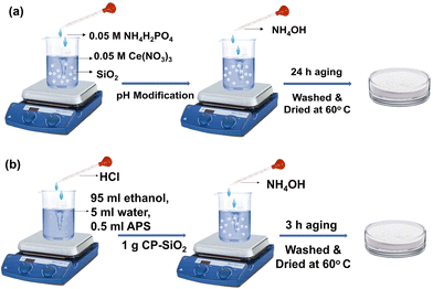
A hybrid of cerium phosphate (CP) and silica pigment was prepared via the wet chemical method (Fig. 1a). After dispersing silica in cerium nitrate hexahydrate solution (0.05 M), ammonium dihydrogen phosphate solution (0.05 M) was added dropwise under stirring. Two wt% of CP precipitated over silica and was labelled as CP-SiO2. The pH of the reaction mixture was adjusted to 8 by adding ammonium hydroxide solution. The reaction mixture was kept at room temperature for 24 hours for ageing. The hybrid pigment was centrifuged and washed with distilled water to attain a neutral pH and dried at 60 °C.Surface modification of the hybrid pigment
The prepared hybrid pigment was functionalised with APS. Hydrolysis reaction was performed with 95 ml ethanol, 5 ml water, and 0.5 ml APS, and stirred at 300 rpm for 2 h at room temperature. The pH of the reaction was adjusted to 2 by adding hydrochloric acid. The hybrid pigment (1 g) was added to the reaction mixture, and the pH was adjusted to 9, using an ammonia solution. The solution was stirred for 3 h to achieve surface modification over the pigment. The surface-modified pigment was collected by centrifugation (6000 rpm), washed with distilled water and ethanol, and dried at 60 °C. The surface functionalized hybrid pigment is labelled as fCP-SiO2, and a schematic representation of surface modification is shown in Fig. 1b.Coating preparation
Steel coupons with 4 × 3 cm dimensions were polished with sandpaper (grit size: 220, 320, 400, 600, 800 and 1000). The coupons were washed in distilled water and degreased with acetone via ultrasonic vibration.The pigment was dispersed in n-butyl alcohol, and commercial epoxy and polyamide curing agents were added in sequence. The epoxy, solvent, and hardener ratio was fixed at 2![[thin space (1/6-em)]](https://www.rsc.org/images/entities/char_2009.gif) :
:![[thin space (1/6-em)]](https://www.rsc.org/images/entities/char_2009.gif) 2
2![[thin space (1/6-em)]](https://www.rsc.org/images/entities/char_2009.gif) :
:![[thin space (1/6-em)]](https://www.rsc.org/images/entities/char_2009.gif) 1. The resultant coating solution was coated on the cleaned coupon using a dip-coating instrument with a dipping rate of 80 mm min−1 and 1 min immersion time. Eventually, the coating was cured at room temperature for 24 hours. In a similar procedure, silica (5, 10, and 15 wt%) and a 10 wt% of hybrid pigment embedded commercial epoxy-polyamide matrix was prepared.
1. The resultant coating solution was coated on the cleaned coupon using a dip-coating instrument with a dipping rate of 80 mm min−1 and 1 min immersion time. Eventually, the coating was cured at room temperature for 24 hours. In a similar procedure, silica (5, 10, and 15 wt%) and a 10 wt% of hybrid pigment embedded commercial epoxy-polyamide matrix was prepared.
Techniques
Commercial silica and hybrid pigment composition were analysed by powder X-ray diffraction (PXRD) using a Philips X′pert Pro diffractometer from 2θ = 5° to 70° with Cu Kα as a radiation source. A Bruker Alfa-E Fourier transform infrared (FT-IR) spectrometer was used to confirm the hybrid formation and surface functionalisation using a spectral range of 4000–400 cm−1 with a resolution of 4 cm−1 in the attenuated total reflection (ATR) mode. The thermal properties of the pigment were examined using a thermogravimetric analyser (TG-DTA 6200, SII Nanotechnology Inc.). Pigments were heated from 30 to 1000 °C under a N2 atmosphere at a 5 °C min−1 heating rate and a N2 flow of 150 mL min−1. N2 adsorption–desorption isotherms were plotted using a Micromeritics Tristar analyser. The microscopic investigation was performed using Field emission scanning electron microscopy (FESEM, JEOL JSM5600 model) and high-resolution and transmission electron microscopy (HRTEM; FEI Tecnai 30 G2 S-TWIN microscope, The Netherlands). The pigments were outgassed under vacuum at 200 °C for 3 h. Constant temperature and pressure ranged from 0.01 to 0.99, and data were collected by admitting or removing N2 gas over the pigment. The specific surface area was calculated using the Brunauer–Emmett–Teller (BET) model, and the pore volume versus diameter distribution was calculated using the Barrett–Joyner–Halenda (BJH) method. The surface chemistry of the synthesised pigments was analysed using X-ray photoelectron spectroscopy (XPS). The analysis was performed with a PHI 5000 VersaProbe II machine manufactured by ULVAC-PHI Inc. in the USA. The machine was equipped with a micro-focused monochromatic Al-Kα X-ray source, with a beam size of 200 μm and energy of 15 kV (hν = 1486.6 eV). Both survey scans and high-resolution spectra were recorded. The survey scans were recorded with a 50 W X-ray source power and 187.85 eV pass energy. High-resolution spectra of the major elements were recorded at a 46.95 eV pass energy. The contact angle of the coating with the surface-treated hybrid pigment was measured using the sessile drop method. The dry thickness of the coating was measured using a profilometer.Electrochemical analysis was performed on an Autolab potentiostat/galvanostat analyser by Metrohm (The Netherlands) utilised for electrochemical impedance spectroscopy (EIS) analysis to evaluate the corrosion resistance of coatings in a 3.5% NaCl solution. The working electrode and coated steel coupon (4 × 3 cm) were placed into flat corrosion cells, with a 1 cm2 coupon exposed to 3.5% NaCl solution. Graphite and saturated calomel electrodes were used as counter and reference electrodes. Intact coat and scratched coat coupons were analysed. A surgical lancet was used to create a scratch in the coated sample. The open-circuit potential was measured for 1 h followed by EIS measurements with a frequency ranging from 105 to 10−2 Hz using an alternating current signal with an amplitude of 10 mV. EIS data were fitted to equivalent circuit diagrams using the Ec-lab software.
Results and discussion
Characterisation of the hybrid pigment
The PXRD patterns of silica and the hybrid pigment (CP-SiO2) are shown in Fig. 2a. The PXRD pattern of the commercial precipitated amorphous silica displayed a typical broad peak around 23° associated with the amorphous phase.27,28 Hybrid pigment formation, evidenced from the diffractogram (CP-SiO2), holds significant cerium phosphate peaks and amorphous silica. The hybrid pigment shows a 2θ peak at 28.7, 31.1, 37.3, 41.0, 41.9, 48.4, 52.4, 53.9 and 59.4 degrees, symbolising the cerium phosphate incorporation into amorphous silica. An unknown low intensity peak at 15° seems to be there in a diffractogram of the hybrid pigment.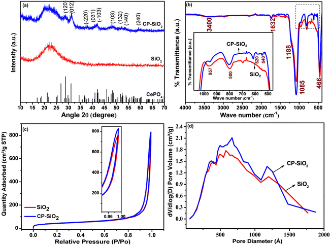 | ||
| Fig. 2 (a) PXRD pattern, (b) IR spectra, (c) N2 adsorption and desorption isotherms from BET analysis and (d) BJH pore size distribution of silica and hybrid pigment CP-SiO2. | ||
Furthermore, IR results confirm the hybrid formation and IR spectra of SiO2 and the CP-SiO2 hybrid pigment displayed in Fig. 2b. Commercial silica displays peaks in its infrared spectrum at 1085 cm−1, with a shoulder at 1188 and 957 cm−1. These peaks are typically attributed to asymmetric stretching vibrations involving Si–O–Si and are assigned to the transverse optical phonon-TO and longitudinal optical phonon-LO modes.29 The IR band at 3400 cm−1 is due to the stretching vibration of water molecules. Consistently, the IR band at 1632 cm−1 is due to water molecule bending vibrations.27,28 The IR band at 800 cm−1 is due to Si–O–Si symmetric stretching vibrations, whereas 466 cm−1 represents O–Si–O bending vibrations. The 1000–1100 cm−1 vibration corresponds to the asymmetric stretching vibration of PO4 tetrahedra in CP. Peaks at 540 and 620 cm−1 are assigned to the bending vibration of P–O, a typical feature of phosphates (displayed in the inset of Fig. 2b).28,30,31 CP-SiO2 shows IR bands of both CP and SiO2, evidencing the hybrid pigment formation and confirming the PXRD results.
The BET isotherm and the distribution of pores in the silica and hybrid pigment were obtained from BET N2 adsorption–desorption analysis, as shown in Fig. 2c and d. The isotherms describe a sharp capillary condensation step at high relative pressure, showing that all samples correspond to isotherms of type II (IUPAC). Significantly similar pores and hysteresis loop (H3) sustained in the hybrid pigments. The isotherm depicts the loose assembly of primary particles forming slit-like pores.32 The slit-like poresize distribution was broad, with the majority falling in the diameter range of 50 to 100 nm (Fig. 2d). This indicates specifically the macro-porosity in the SiO2 particle. Changes observed in the BET-specific surface area, pore size, and pore volume associated with hybrid pigment formation are tabulated in Table S1.†
CP-SiO2 was further examined by XPS analysis to confirm the surface composition of the material and to reveal the valence chemical state of the individual element. The presence of cerium and phosphorus over silica is confirmed by the XPS survey data shown in Fig. 3a.
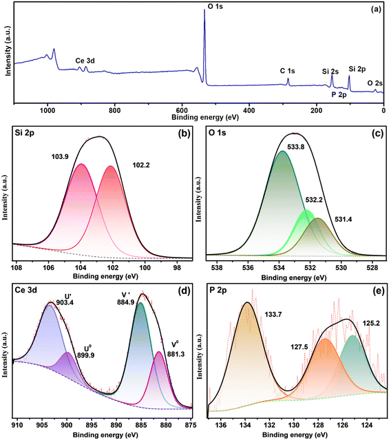 | ||
| Fig. 3 XPS spectra of CP-SiO2 (a) and survey and high-resolution spectra of (b) Si 2p, (c) O 1s, (d) Ce 3d and (e) P 2p. | ||
High-resolution spectra of Si 2p show peaks around 102.2 and 103.9 eV, attributed to the indication of Si–O and Si–P bonding in the hybrid pigment (Fig. 3b).33 Three peaks of the O 1s spectra of CP-SiO2, centred at 531.4, 532.2 and 533.8 eV, developed from Ce–O, P–O and Si–O bonding, respectively (Fig. 3c). Four peaks were detected in the Ce 3d spectrum around 881.3, 884.9, 899.9 and 903.4 eV, corresponding to two spin–orbit features (Ce 3d5/2 and 3d3/2).34–37 Therefore, the existence of the Ce(III) oxidation state in the hybrid pigment was confirmed from Ce 3d deconvolution (Fig. 3d). P 2p evaluation provides a chemical state of phosphorus, as shown in Fig. 3e. The literature value for phosphate was found to be around 133 eV.38,39 The deconvoluted peak at 127.5 eV binding energy reported for phosphide indicates Si–P bonding.33 With this result, the correlation with the 15° PXRD peak matches the silicon phosphide (SP). The shift in binding energy is due to the higher electronegativity of P than that of Si. XPS confirms the formation of a chemically active CP over silica and reveals the unexpected chemical behaviour of phosphorus (silicon phosphide) in the hybrid pigment. The excess peak around 125.2 eV is attributed to the satellite peak of cerium 4d3/2. XPS results disclosed the formation of cerium phosphate and silicon phosphide by adding cerium and phosphorus precursors with silica.
The morphological feature was recognised from micrographs. The SEM images of commercial silica shown in Fig. 4a reveal uneven particle size and shape. The prepared hybrid pigment CP-SiO2 retained the same morphology as silica (Fig. 4c). Furthermore, the TEM analysis was performed to disclose the depth of internal structural information. Unlike the micron size particle in the SEM image, TEM inspection with a high magnification revealed a cluster of primary SiO2 nanoparticles having a size in the range of ∼10 to ∼20 nm. The observed TEM image displayed a brighter region between the SiO2 primary particles, indicating the porosity in the nanoparticle cluster (Fig. 4b and d). Porosity can be explained as the ratio of the total pore volume to the volume of the particle or agglomerate. The micrographic results match well with the BET isotherm. Energy dispersive X-ray color-coded maps show the elemental (Si, O, Ce, and P) distribution on the surface of the synthesised pigment (Fig. 4e).
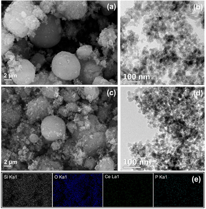 | ||
| Fig. 4 Micrograph of silica and CP-SiO2 (a and c), SEM images (b and d), TEM images and (e) SEM elemental mapping of CP-SiO2. | ||
Characterisation of a silane functionalised hybrid pigment
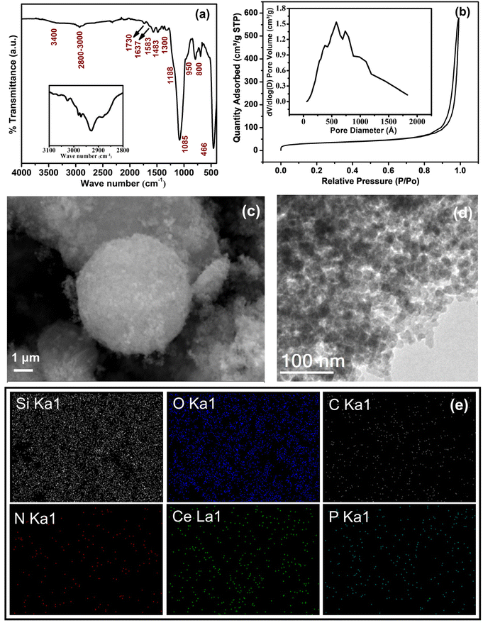
Surface treatment is utilised to acquire a hydrophobic hybrid pigment, which is confirmed using IR spectra. Along with the IR bands of hybrid silica CP-SiO2, bands appeared at 1483 and 1583 cm−1, corresponding to bending vibrations of C–H and N–H. Thus, it confirms the covalent bond formation between the APS and the surface of CP-SiO2.40 The band at 1730 and 1637 cm−1 indicates the C![[double bond, length as m-dash]](https://www.rsc.org/images/entities/char_e001.gif) O stretching vibration and C
O stretching vibration and C![[double bond, length as m-dash]](https://www.rsc.org/images/entities/char_e001.gif) C stretching vibration (Fig. 5a). Formation of the band around 2800–3000 cm−1 (Fig. 5a inset) is due to asymmetric C–H stretching of –CH3 and that at 1300 cm−1 corresponds to Si-CH2-R, which also indicates the APS surface modification over the hybrid pigment.41 The BET results of fCP-SiO2 indicate a single-point surface area of 110.57 at P/P0 = 0.273853. The BET surface area of fCP-SiO2 is 112.58. The BJH desorption cumulative surface area of pores ranging from 1.7 nm to 30 nm in diameter is 94.68. Lastly, the average pore diameter of the desorbed BJH is 38.25. These results suggest that fCP-SiO2 has only a slight variation in surface area and porosity with the CP-SiO2 pigment. The isotherms from BET analysis with the inset of BJH pore size distribution are shown in Fig. 5b. The micrographic SEM and TEM images of fCP-SiO2 are presented in Fig. 5c and d, respectively. The silane functionalisation on CP-SiO2 is expected to enhance the interaction of the filler with the epoxy matrix and the interfacial force between the filler and epoxy due to siloxane bond formation. Energy dispersive X-ray generated colour-coded maps visually represent the elemental distribution across the surface of a sample (Si, O, C, N, Ce, and P) as shown in Fig. 5e.
C stretching vibration (Fig. 5a). Formation of the band around 2800–3000 cm−1 (Fig. 5a inset) is due to asymmetric C–H stretching of –CH3 and that at 1300 cm−1 corresponds to Si-CH2-R, which also indicates the APS surface modification over the hybrid pigment.41 The BET results of fCP-SiO2 indicate a single-point surface area of 110.57 at P/P0 = 0.273853. The BET surface area of fCP-SiO2 is 112.58. The BJH desorption cumulative surface area of pores ranging from 1.7 nm to 30 nm in diameter is 94.68. Lastly, the average pore diameter of the desorbed BJH is 38.25. These results suggest that fCP-SiO2 has only a slight variation in surface area and porosity with the CP-SiO2 pigment. The isotherms from BET analysis with the inset of BJH pore size distribution are shown in Fig. 5b. The micrographic SEM and TEM images of fCP-SiO2 are presented in Fig. 5c and d, respectively. The silane functionalisation on CP-SiO2 is expected to enhance the interaction of the filler with the epoxy matrix and the interfacial force between the filler and epoxy due to siloxane bond formation. Energy dispersive X-ray generated colour-coded maps visually represent the elemental distribution across the surface of a sample (Si, O, C, N, Ce, and P) as shown in Fig. 5e.
Fig. 6a depicts the XPS survey spectra of fCP-SiO2, and Fig. 6(b–g) shows the deconvoluted high-resolution spectra of constituent elements. Fig. 6b illustrates the C 1s deconvoluted high-resolution spectra, where along with the graphitic carbon peak (284.6 eV), the appearance of a peak at 285.9 eV with a low intensity shoulder peak confirms the C–N bonding and silane surface functionalisation.42,43 The deconvoluted N peaks at 399.9 eV and 402.3 eV symbolise free amine, protonated or hydrogen-bonded amine, respectively. The N 1s spectrum confirms the APS surface modification (Fig. 6c).44,45
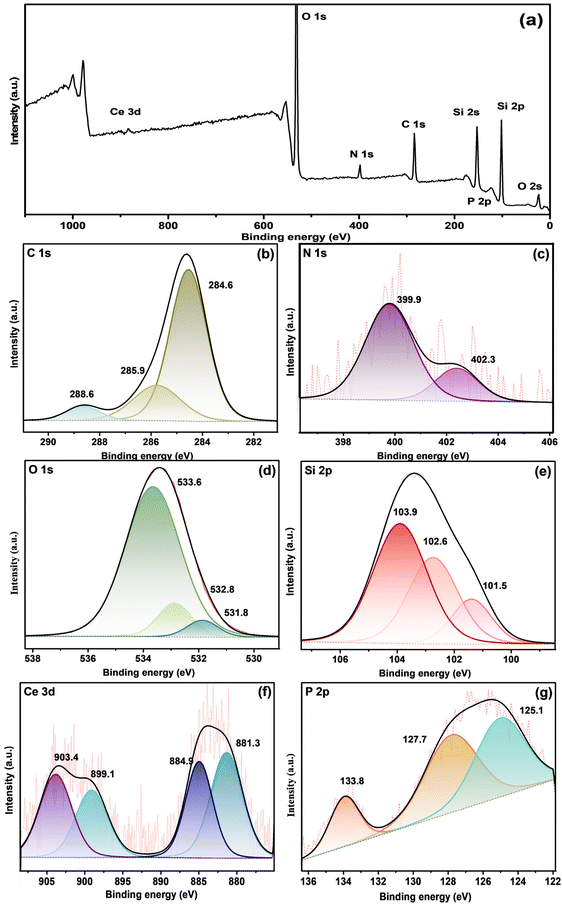 | ||
| Fig. 6 (a) XPS survey spectrum fCP-SiO2 and High-resolution XPS spectra of (b) C 1s, (c) N 1s, (d) O 1s, (e) Si 2p, (f) Ce 3d and (g) P 2p orbitals. | ||
Surface-modified hybrid pigment O 1s core spectral peaks around 533.6, 532.8 and 531.8 eV correspond to Si–O, P–O and Ce–O bonding (Fig. 6d).45 Moreover, the Si 2p spectra are separated into Si–O–C (101.5 eV), Si–O–Si (103.9 eV), and Si–P (102.6 eV) as shown in Fig. 6e.46 fCP-SiO2 exhibits high-resolution spectra of Ce 3d and P 2p similar to CP-SiO2 as shown in Fig. 6f and g. Consistent with the IR spectra, the XPS analysis results also show successful surface modification of CP-SiO2 with APS.41
Characterization of the coating
The contact angle between water and coatings was optically measured using the sessile drop method (Fig. S1a–c†). Even though epoxy has strong chemical stability and adhesion properties, due to the polar epoxy group, it provides a hydrophilic surface, as shown in Fig. S1a.† The hydroxyl group on the silica surface makes it naturally hydrophilic. The hydrophilicity contribution of silica and epoxy resulted in a hydrophilic surface in the CP-SiO2 embedded epoxy coating (Fig. S1b†).The water-repellent nature of the surface-treated pigment fCP-SiO2 provides a hydrophobic coating (Fig. S1c†). The alkyl groups in the APS replace the hydroxyl group on CP-SiO2, creating the covalent bonding with the epoxy binder and enhancing the barrier property of the coating.
Electrochemical impedance analysis
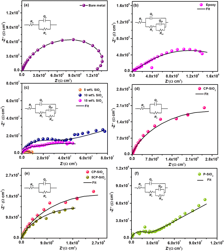
The small magnitude of alternating current perturbation (0.005 V) at the steady state (open circuit potential) is observed from the EIS data. The impedance spectra of the bare metal and all coated steel coupons (bare epoxy, silica and hybrid pigment incorporated epoxy) were analysed in a 3.5 wt% NaCl solution (Fig. 7). For quantitative information, impedance data were fitted into two different equivalent circuits based on the type and age of a particular coating given in Fig. S2.†Rs denotes solution resistance, Rc represents coat resistance and the corresponding capacitance is Qc, Rct signifies charge transfer resistance and Qdl is the associated double-layer capacitance. Pure capacitance is replaced with the constant phase element (Q) by considering surface heterogeneity.47Bare steel shows poor resistance (1200 Ω cm2 – Fig. 7a) towards a corrosive environment (3.5% NaCl solution). Epoxy is chosen as the binder in the coating solution based on chemical and moisture stability. The bare epoxy coating exhibits a charge transfer resistance of 2.05 × 10⁶ Ω cm2 during the early immersion stage due to pore formation during the curing process. In the early immersion stage, the bare epoxy coating exhibits charge transfer resistance at 2.05 × 10⁶ Ω cm2 due to pore formation during the curing process (Fig. 7b). The electrochemical parameters are tabulated in Table 1.
| Sample | R c (Ω cm2) | Q c | R ct (Ω cm2) | Q dl | ||
|---|---|---|---|---|---|---|
| Y 0 (Ω−1 cm−2 Sn) | n 1 | Y 0 (Ω−1 cm−2 Sn) | n 2 | |||
| Epoxy | 1.63 × 10⁵ | 2.72 × 10⁻⁷ | 0.7 | 2.05 × 10⁶ | 1.13 × 10⁻⁶ | 0.6 |
| 5 wt% SiO2 | 7.96 × 10⁶ | 1.84 × 10⁻⁶ | 0.7 | 9.25 × 10⁷ | 2.37 × 10⁻⁸ | 0.4 |
| 10 wt% SiO2 | 1.36 × 10⁷ | 2.59 × 10⁻⁸ | 0.3 | 3.71 × 10⁸ | 1.33 × 10⁻⁹ | 0.9 |
| 15 wt% SiO2 | 4.98 × 10⁶ | 2.48 × 10⁻⁸ | 0.4 | 7.86 × 10⁷ | 1.39 × 10⁻⁹ | 0.9 |
| CP-SiO2 | 5.76 × 10⁹ | 1.05 × 10⁻⁹ | 0.7 | |||
| 5CP-SiO2 | 4.38 × 10⁹ | 1.04 × 10⁻⁹ | 0.6 | |||
| P-SiO2 | 2.86 × 10⁷ | 8.45 × 10⁻⁸ | 0.8 | 8.22 × 10⁸ | 5.98 × 10⁻⁹ | 0.9 |
The anticorrosive nature of silica and optimum loading in the epoxy-polyamide matrix were evaluated using EIS and are displayed in Fig. 7c. The steel coupons coated with various wt% (5, 10, and 15 wt%) silica-loaded epoxy were a better corrosion-resistive system than a pristine epoxy coating. Silica particles act as obstacles to the penetration of the corrosive medium. Silica coating with 10 wt% loading shows superior resistance. However, the increase in wt% does not follow the trend. Higher loading than optimum (10 wt%) leads to a viscous coating solution that provides poor dispersion, resulting in aggregation and unwetted pigment in the epoxy-polyamide matrix, which significantly drops the barrier property of the coating. However, a bare silica-incorporated epoxy coating produces the second-time constant at initial harsh exposure, showing poor integrity of the silica coating.
Furthermore, CP-SiO2 was assessed by electrochemical impedance spectroscopy (Fig. 7d). The impedance value of CP-SiO2 incorporated coatings is higher than those obtained for silica-loaded coating. The higher active component (5 wt% of cerium and phosphorus precursor) is labelled as 5CP-SiO2. Nyquist results of 10 wt% 5CP-SiO2 confirm that 2 wt% of CP (CP-SiO2) is sufficient for enhancing the performance of the coating (Fig. 7e). EIS results revealed that the coating loaded with hybrid pigments exhibits capacitive behaviour and higher impedance values than silica. At the lower frequency region, the lower capacitive nature of bare epoxy and the silica-incorporated coating reveals their inferior efficiency compared to the coatings with the hybrid pigment. Silica-incorporated coatings exhibit a barrier mechanism. In contrast, the hybrid pigment provides additional prevention, as evidenced by high coat resistance. Also, EIS spectra were utilised to reveal the physicochemical process on steel in a corrosive medium (3.5% NaCl solution). EC-lab software fitted impedance data of each electrical equivalent circuit element are given in Table 1. The high coat resistance Rc and capacitive nature of the hybrid pigment coating evidenced the intactness of the coating, where corrodent (water, oxygen or corrosive ion) transportation is impossible through the coating. To acknowledge the role of CP, the hybrid pigment was prepared without a cerium precursor and evaluated the accomplishment using EIS (P-SiO2). The enhanced impedance of the CP-SiO2-epoxy coating is attributed to CP and SP (Fig. 7f).
Additionally, bode plots were evaluated to support the Nyquist results of different coatings of SiO2/epoxy, P-SiO2/epoxy, CP-SiO2/epoxy and fCP-SiO2/epoxy shown in Fig. S3.† The phase shift or time constant associated with different processes in the coating systems is displayed as a function of frequency in the Bode plot. The Bode plot of SiO2/epoxy and P-SiO2/epoxy exhibits a peak in the lower frequency region attributed to the steel corrosion process (Fig. S3a and S3b†). The phase angle in the high (104–105 Hz) and middle (100–103 Hz) frequency regions of CP-SiO2/epoxy of higher than 80 degrees and that of the fCP-SiO2/epoxy coating around 90 degrees illustrate the good performance and intactness of the coating. EIS results evidenced the enhanced restiveness of the synthesised pigment than the SiO2 and P-SiO2 reinforced epoxy coating towards the penetration of corrosive ions and water molecules.48,49 Moreover the high impedance modulus at lower frequency (|Z|0.01 Hz) of the synthesized pigment supports the barrier nature of the formulated coating.50
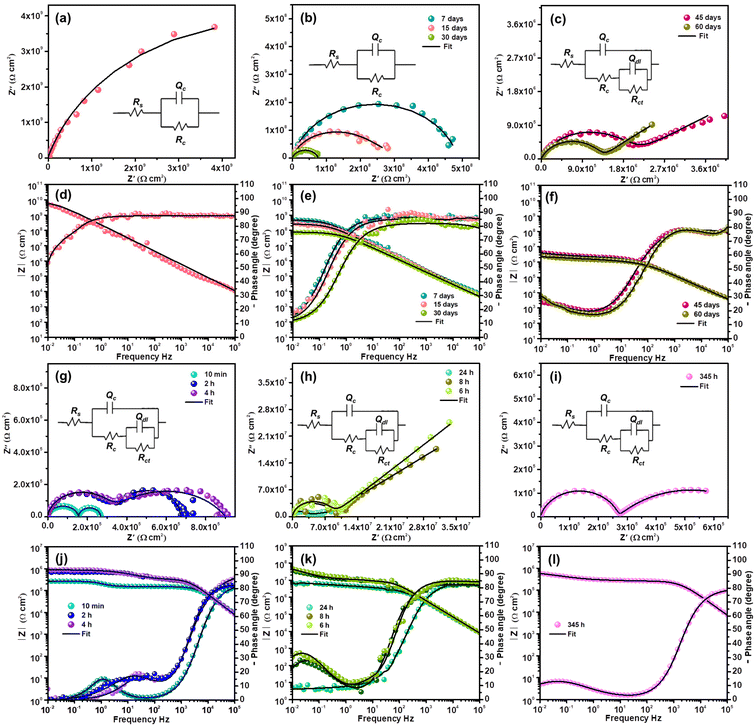
The entanglement of epoxy with the APS groups of fCP-SiO2 occurs. An increase in cross-link density influences the resistance property of the resultant coating. Due to greater interaction between the surface-treated pigment and epoxy, a low capacitance (Cc = 5.33 × 10⁻⁹ Ω−1 cm−2 Sn) was gained among other coatings, as shown in Table S2.† The EIS analysis results of fCP-SiO2 are presented in Fig. 8a. Around the surface treated hybrid pigment in the epoxy matrix, there is a unique vicinity of different morphologies, creating a hydrophobic surface and thereby preventing water and electrolyte penetration. EIS results show a significant variation in Rc values for surface-treated and non-treated hybrid pigment-embedded epoxy-polyamide matrices.
For continuous immersion of the efficient coating in a corrosive medium, a conventional procedure was adopted to explain the durability and corrosion prevention mechanism. After a few days of immersion, coating resistance at low frequencies and the capacitive nature of the coating decrease gradually, revealing the formation of fine capillary channels in the coating (Fig. 8b). The capacitor performance or intactness of the coating is revealed by the single semi-circle, as shown by 30 days of impedance evaluation. The formation of Rct in the impedance spectrum suggests that electrochemical reactions originated at the metal–coating interface.26
Subsequently, in the EIS spectrum at the end of the first semi-circle, an arc developed after 45 days of immersion corresponding to the faradaic process beneath the coating (Fig. 8c). Coating resistance decreases, implying that the corrosive medium starts to penetrate through the pores, and the generation of further pores decreases the barrier property of the film. An increase in permittivity eventually shifted the capacitance of the coating to a large extent. The capacitive nature of the second loop shows the controlled reaction process. The electrochemical data were obtained using a circuit with two apparent time constants. The high capacitance arc exhibited reaction progress beneath the coating in a self-restrained aspect (Fig. 8c).
The Bode plots in Fig. 8d–f substantiate the Nyquist results. At the beginning of the immersion, the impedance modulus (|Z|0.01 Hz ≃ 1010 Ω cm2) of fCP-SiO2 was higher than those of other coating formulations at the onset of immersion. The impedance modulus is continuously monitored to reveal the effectiveness of the coating and detect the early signs of degradation. After immersion of 7 days the |Z|0.01 Hz is 5.67 × 10⁸ Ω cm2, implying the activation of the coating by the aggressive saline environment and gradual reduction of the barrier performance. The impedance modulus diminishes to 8.65 × 10⁷ Ω cm2 after 30 days of continuous immersion in 3.5 wt% NaCl solution, but still the coating delivers acceptable corrosion resistance. The coating capacitance 4.75 × 10⁻⁹ Ω−1 cm−2 Sn after immersion of 30 days shows the prolonged service life of the coating. After continuous immersion for 45 days in the low frequency region due to the double-layer capacitance of the corrosion region, aggressive corrosive ions start penetrating into the defect of the coating, probably due to electrochemical reaction at the metal–coating interface. To know the mechanism of the active inhibition of the hybrid pigment, EIS is highly precise and capable of evaluating kinetics and diffusion, providing the details of charge transfer parameters and double-layer behaviour at the metal–coating interface. The charge transfer resistance 5.09 × 10⁶ Ω cm2 (45 days) slightly increased to 1.41 × 10⁷ Ω cm2 (60 days), owing to inhibitive layer formation at the defective site due to continuous immersion in the harsh saline environment. The gain in capacitance from 5.33 × 10⁻⁹ to 2.54 × 10⁻⁶ Ω−1 cm−2 Sn endorsed the penetration of the corrosive medium through the generated coat defects.
The diffusion coefficient (D) of the metal–coating interface was calculated using simplified Fick's second law of diffusion.51,52
![[thin space (1/6-em)]](https://www.rsc.org/images/entities/char_2009.gif) Qc − t1/2 (Fig. S5†). This further suggests comparable barrier performance of fCP-SiO2/epoxy with the reported coatings.51,52
Qc − t1/2 (Fig. S5†). This further suggests comparable barrier performance of fCP-SiO2/epoxy with the reported coatings.51,52
To disclose the active inhibitive role of the coating, artificial defects with dimensions of 1 cm length and 15 μm depth (from a profilometer) were created using a surgical knife. The electrochemical behaviour of the defective coupon in 3.5% NaCl was continuously monitored using the EIS technique. Since the charge carriers are permeable through the artificial crack, the OCP of the coupon (−0.61 V (with respect to the SCE)) is close to the OCP of the bare metal (−0.65 V (with respect to the SCE)). The high value of capacitance Cc with consistently poor Rc also indicates the ingress of the corrodent.26 The impedance curve consists of two semi-circles at the initial immersion time (10 min), suggesting a corrosion process through the artificial defect. Two well-distinguishable semi-circles become two overlapped semi-circles in succeeding EIS analysis (2 h) with a slight increment in resistance, confirming the initiation of the corrosion inhibition process at the metal–coating interface.
Migration of electrolytes through the coating involves a reaction process with the active component of the coating marginally increasing the impedance. The active components in the coating are released and adsorb on the surface of the exposed steel surface by replacing the water molecules previously occupying the steel surface. The consecutive EIS result (4 h) again shows the increment in impedance, and the Nyquist plot appears to be well-merged (Fig. 8g). The sequential Nyquist plot appeared as a single semi-circle with a capacitive arc at the tail, implying a controlled diffusion process, possibly due to passive layer formation at the metal–coating interface (Fig. 8h). The second time constant is the impedance value obtained by extrapolating the arc to the X-axis. The capacitive nature of the arc weakened in the subsequent Nyquist plots indicates the progression of flaws due to a strong corrosive medium (Fig. 8i).
The minimal resistance variation during prolonged immersion, even in a corrosive medium, manifests the active inhibition action of the coating at the metal–coating interface. Fig. 8i shows the impedance after 2 weeks of continuous exposure to a corrosive medium. The partial recovery of the anticorrosive performance substantiates the self-healing nature of the coating. The impedance parameters are presented in Table S2.†
The Bode plots of the defective coating are shown in Fig. 8j–l. In general, the distinct peaks at varying frequencies in the Bode plots reveal the different phenomena. The peak between 104 to 105 Hz is predominantly associated with the responses generated by the protective coating, which plays a crucial role in safeguarding the underlying metal surface. Whereas, the peak at 100 to 103 Hz shows the responses connected to defects in the coating. Eventually, the low-frequency peak at 10−2 to 100 Hz illustrates the corrosion processes on the steel surface.50 The phase angle plot at 10 minutes, shown in Fig. 8j, clearly exhibits the low frequency peak (around 100 Hz) related to the corrosion process in the defective site. After 4 h exposure, the peak shifted between 101 and 102 Hz due to corrosion product formation at the defective site, with restriction of the passage of the corrosive medium which results in improvement in the impedance modulus (1.11 × 10⁵ to 3.26 × 10⁵ Ω cm2). Even after 24 h of continuous exposure the impedance modulus remained at 8.35 × 10⁶ Ω cm2 and 345 h of immersion resulted in 3.98 × 10⁵ Ω cm2.
The SEM image of the defective coating is shown in Fig S3a† and the corresponding profile image is generated using WSxM software as displayed in Fig S3b† (to extract cross-sectional profiles from SEM images); these enable the analysis of the height, depth, and width of the artificial defect. The depth of the defect matches with the coating thickness measured using the profilometer (15–20 micrometer). The artificial defect coating taken for SEM analysis after continuous impedance measurement in 3.5 wt% NaCl solution is shown in Fig S3c.† The generated profile of the surface revealed changes in height or depth along a selected cross-section, and the defective site was covered with the corrosion products. Furthermore, the corrosion product evaluated using SEM-EDX analysis, which clearly shows the presence of Fe, O and P, reveals the corrosion product and inhibitive layer formation. Even though the active performance of phosphate is confirmed from the SEM-EDX results, the active participation of cerium not visualized may be due to the trace amount of cerium trapped between the corrosion products. Furthermore, to understand the chemistry of the inhibitive layer XPS analysis was carried out.
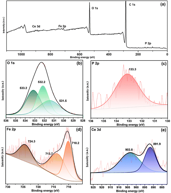
The survey spectrum confirmed the presence of Fe, O, Ce, and P shown in Fig. 9a, and deconvoluted O 1s, P 2p, Fe 2p and Ce 3d are shown in Fig. 9(b–e). The O 1s spectrum generated three peaks at 533.2, 532.2, and 531.5 eV binding energies. The peak of the O 1s deconvolution shows the presence of hydroxide and phosphate components. A peak position at 532.3 eV was reported for FePO4 (Fig. 9b).53 The binding energy at 133.3 eV (Fig. 9c) is associated with PO43−. Three peaks at 710.2, 724.3 and 713.7 eV in Fig. 9d belong to iron oxide (Fe 2P3/2 and Fe 2P1/2) and FePO4, respectively. The occurrence of Ce in the core spectrum confirms cerium hydroxide formation in the defective region (Fig. 9e).
Consequently, XPS results concur with the EIS results for forming an inhibitive iron phosphate layer beneath the coating during self-healing. As a result, the active components in the hybrid pigment started to react on the defect area at the initial stage of the complex corrosion process. Iron phosphate and cerium hydroxide formation occurs at the defective site, possibly due to Ce3+, Fe3+, OH− and phosphorus combined reactions. The possible inhibitive layer mechanism can be written as follows: eqn (1)–(5).
| O2 + 4e− + 2H2O → 4OH− | (1) |
| Ce3+ + 3OH− → Ce(OH)3 | (2) |
| Ce(OH)3 + OH− → Ce(OH)4 | (3) |
| Fe → Fe3+ + 3e− | (4) |
| 3Fe3+ + 3PO43− + 8H2O → Fe3(PO4)3·8H2O | (5) |
The iron phosphate and cerium hydroxide film acts as a corrosion barrier at artificial cracks during corrosion.54 Compared with conventional phosphate pigments like zinc phosphate, the hybrid pigment CP-SiO2 also shows inhibitive performance.55–57
Mechanism of protection
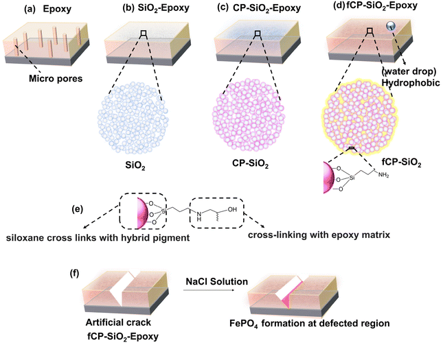
Fig. 10(a–d) shows the different types of coatings used in the study: bare epoxy, SiO2, CP-SiO2, and fCP-SiO2 embedded epoxy coatings. The micropore in bare epoxy allows corrosive substances to reach the metal surface, leading to corrosion (Fig. 10a). However, when silica is added to the coating, it reduces the porosity and increases the density, thus making it more resistant to corrosion (Fig. 10b). Furthermore, cerium and phosphorus precursor modified silica provides active–passive protection, making it even more effective against corrosion (Fig. 10c).CP-SiO2 is subjected to silane surface functionalisation, which reduces the hydrophilicity of silica and introduces hydrophobicity in the epoxy coating. This improves the water-repulsive nature of the coating, preventing the penetration of water into the metal surface (Fig. 10d). APS provides siloxane cross-links with the hybrid pigment, whereas the organofunctional group (–NH2) delivers dense cross-linking with an epoxy matrix (Fig. 10e). The silane acts as an adhesion promoter, enhancing the inter-coat adhesion and resisting the development of coat defects, thereby increasing the durability of the coating.
Finally, the EIS analysis confirmed the spontaneous phosphatisation process, which takes place within a few hours of immersion of defective coupons (Fig. 10f). The barrier nature of silica, the active inhibitive action of cerium phosphate, and the hydrophobic surface make the coating an efficient anticorrosive coating.
Comparative analysis with a commercial pigment
Table 2 shows the potential performance of our synthesised pigment in comparison with commonly used chrome and zinc-based pigments. Our group has previously reported on the CPVC and impedance results of commercial pigments. It is important to note that creating a pigment that is free from carcinogenic or toxic elements is crucial for ecological and regulatory reasons.Based on Table 2, our synthesised pigment has the potential to replace efficient but toxic anticorrosive pigments. Our invention provides a hybrid inorganic pigment that is resistant to corrosion, free of harmful elements (specifically chromium), chemically stable, and well-suited for use in harsh saline environments.
Conclusion
A newly developed anticorrosive pigment has excellent properties such as barrier protection, hydrophobicity, and active inhibition through phosphatisation. By modifying conventional silica with a cerium and phosphorus precursor, the anticorrosive performance of the coating has been significantly improved. The hybrid pigments in the coating respond to microanodic regions through the phosphatisation process, which has been systematically explored using EIS and XPS. This work provides a simple, cost-effective strategy to create an efficient, eco-friendly alternative pigment to replace toxic pigments. The surface-modified hybrid pigment fCP-SiO2 incorporated into the transparent epoxy-polyamide coating shows water-repellency, phosphatisation, and barrier performance, which can significantly extend the service life of the coating in saline media.Data availability
The datasets generated during and/or analysed during the current study are not publicly available due to the restriction from the funding agency but are available from the authors on reasonable request.Conflicts of interest
There are no conflicts of interest to declare.Acknowledgements
We thankfully acknowledge the financial support from the DST_WOS-A, Government of India (DST/WOS-A/CS-98/2021(G)). We thank Mr Peer Mohamed A and Mr Kiran Mohan for the XPS and TEM analyses at CSIR-NIIST, Thiruvananthapuram.References
- M. Li, L. Zeng, Y. Chen, L. Zhuang, X. Wang and H. Shen, Int. J. Photoenergy, 2013, 2013, 1–8 Search PubMed.
- Y. M. Atteya, D. R. Barbadikar, A. H. I. Mourad and M. F. Aly, Metall. Mater. Trans. A, 2024, 1–21 Search PubMed.
- C. Kanchanomai, N. Noraphaiphipaksa and Y. Mutoh, Composites, Part B, 2011, 42, 1446–1452 CrossRef.
- R. N. Raja Othman, D. K. Subramaniam, N. Ezani, M. F. Abdullah and K. Z. Ku Ahmad, Polymers, 2022, 14, 1–13 CrossRef.
- S. Pal, M. Kumar Sharma, R. Chatterjee, A.-L. Fotouhi, P. Seyed Dorraji, Y. Sadat Seyed Keshmiri, S. A. Al-Shawi, L. S. Alansari, A. Ali Diwan and A. Alkhatat, Mater. Sci. Eng., 2021, 1094, 012142 Search PubMed.
- D. Ratnam and S. K. Bhaumik, Prog. Org. Coat., 2024, 188, 108264 CrossRef CAS.
- H. Guo, C. Yang, H. Sun, N. Xiang and C. Wang, Surf. Interfaces, 2024, 46, 104057 CrossRef CAS.
- X. Li, S. Du, C. Ma, T. Shi, W. Qi and H. Yang, Ceram. Int., 2024, 50, 9469–9478 CrossRef CAS.
- Y. Teng, X. Wei, B. Wu, Y. Liu, N. Fan, Y. Ma, F. Wang, X. Dou, X. Yang and W. Zhang, Colloids Surf., A, 2024, 683, 132940 CrossRef CAS.
- B. Jiang, Y. Lei, K. Sun, Q. Chen, F. Zhang, Y. An, Y. Zhang, Y. Lin, Y. Yuan, T. Liu and X. Li, Colloids Surf., A, 2024, 683, 132846 CrossRef CAS.
- H. Cheng, C. Hu, X. Wang and Z. He, Int. J. Electrochem. Sci., 2018, 13, 196–208 CrossRef CAS PubMed.
- L. Ma, F. Chen, Z. Li, M. Gan, J. Yan, S. Wei, Y. Bai and J. Zeng, Composites, Part B, 2014, 58, 54–58 CrossRef CAS.
- Q. Yu, J. Xu, J. Liu, B. Li, Y. Liu and Y. Han, Appl. Surf. Sci., 2012, 263, 532–535 CrossRef CAS.
- S. Silviana, L. Candra and F. Dalanta, Mater. Chem. Phys., 2024, 315, 129044 CrossRef CAS.
- A. Privitera, S. Tuti, U. Pasqual Laverdura, A. R. Taddei, L. Ruggiero, L. Duranti, E. Di Bartolomeo, M. A. Ricci and A. Sodo, J. Mater. Sci., 2024, 59, 2497–2521 CrossRef CAS.
- J. Pan, X. Liu, X. Cao, X. Ma, Y. Hu, G. Cai, X. Zhang and Z. Dong, Prog. Org. Coat., 2024, 187, 108161 CrossRef CAS.
- V. Mahalingam, M. Sivaraju, G. S. Kumar, K. Lalithambigai, S. R. Priyan and M. M. Alam, Mater. Chem. Phys., 2024, 313, 128752 CrossRef CAS.
- J. E. D. López-Campos, J. Mojica-Gómez, A. Maciel-Cerda, V. M. Castaño and G. Hernández-Padrón, J. Coat. Technol. Res., 2023, 21, 559–574 CrossRef.
- L. Shi, H. Yan, S. Zhao, L. Zhang and X. Fan, Appl. Surf. Sci., 2024, 655, 159662 CrossRef CAS.
- Z. Ahmad, Principles of Corrosion Engineering and Corrosion Control, Butterworth-Heinemann, 2006, pp. 382–437 Search PubMed.
- S. Mandal, J. K. Singh, D. E. Lee and T. Park, Materials, 2020, 13, 1–24 CrossRef.
- Y. Morozov, L. M. Calado, R. A. Shakoor, R. Raj, R. Kahraman, M. G. Taryba and M. F. Montemor, Corros. Sci., 2019, 159, 108128 CrossRef CAS.
- N. Jayakumar, K. Karattu Veedu and N. K. Gopalan, ACS Appl. Nano Mater., 2019, 2, 2689–2696 CrossRef CAS.
- M. J. Palimi, M. Rostami, M. Mahdavian and B. Ramezanzadeh, Appl. Surf. Sci., 2014, 320, 60–72 CrossRef CAS.
- A. A. Javidparvar, B. Ramezanzadeh and E. Ghasemi, J. Taiwan Inst. Chem. Eng., 2016, 61, 356–366 CrossRef CAS.
- F. Dolatzadeh, S. Moradian and M. M. Jalili, Corros. Sci., 2011, 53, 4248–4257 CrossRef CAS.
- S. Musić, N. Filipović-Vinceković and L. Sekovanić, Braz. J. Chem. Eng., 2011, 28, 89–94 CrossRef.
- H. Ren, Y. Ren, A. Li, R. A. Martin and D. Qiu, Biomed. Phys. Eng. Express, 2017, 3, 1–8 Search PubMed.
- M. Kopani, M. Jergel, H. Kobayashi, M. Takahashi, R. Brunner, M. Mikula, K. Imamura, S. Jurecka and E. Pincik, Mater. Res. Soc. Symp. Proc., 2008, 1066, 199–204 CrossRef.
- H. Onoda and R. Tanaka, J. Mater. Res. Technol., 2019, 7–11 Search PubMed.
- H. Onoda and H. Muraki, IOP Conf. Ser.: Mater. Sci. Eng., 2019, 613, 012045 CAS.
- A. Mirzaei, K. Janghorban, B. Hashemi, S. R. Hosseini, M. Bonyani, S. G. Leonardi, A. Bonavita and G. Neri, Process. Appl. Ceram., 2016, 10, 209–218 CrossRef CAS.
- C. Lv, N. Jia, Y. Qian, S. Wang, X. Wang, W. Yu, C. Liu, H. Pan, Q. Zhu, J. Xu, X. Tao, K. P. Loh, C. Xue and Q. Yan, Small, 2023, 19, 2205959 CrossRef CAS.
- C. Tang, Y. Bando, D. Golberg and R. Ma, Angew. Chem., Int. Ed., 2005, 44, 576–579 CrossRef CAS PubMed.
- A. Matraszek, I. Szczygieá, L. Macalik and J. Hanuza, J. Rare Earths, 2009, 27, 598–602 CrossRef.
- G. Vinothkumar, I. L. Arun, P. Arunkumar, W. Ahmed, S. Ryu, S. W. Cha and K. S. Babu, J. Mater. Chem. B, 2018, 6, 6559–6571 RSC.
- M. Lee, S. Kim and D. H. Ko, Appl. Surf. Sci., 2018, 443, 131–137 CrossRef CAS.
- J. Jayaraj, S. A. Kumar, A. Srinivasan, K. G. Raghu, C. Arunchandran and V. Rajinikanth, Appl. Surf. Sci., 2024, 644, 158797 CrossRef CAS.
- A. Kushwaha, G. Singh and M. Sharma, Microchem. J., 2021, 166, 106224 CrossRef CAS.
- P. Rostamzadeh, S. M. Mirabedini and M. Esfandeh, J. Coat. Technol. Res., 2014, 11, 651–660 CrossRef CAS.
- Y. Zhang, M. Zhao, J. Zhang, Q. Shao, J. Li, H. Li, B. Lin, M. Yu, S. Chen and Z. Guo, J. Polym. Res., 2018, 25, 1–13 CrossRef.
- E. T. Vandenberg, L. Bertilsson, B. Liedberg, K. Uvdal, R. Erlandsson, H. Elwing and I. Lundström, J. Colloid Interface Sci., 1991, 147, 103–118 CrossRef CAS.
- F. Zhang and M. P. Srinivasan, Langmuir, 2004, 20, 2309–2314 CrossRef CAS PubMed.
- R. G. Acres, A. V. Ellis, J. Alvino, C. E. Lenahan, D. A. Khodakov, G. F. Metha and G. G. Andersson, J. Phys. Chem. C, 2012, 116, 6289–6297 CrossRef CAS.
- E. T. Vandenberg, L. Bertilsson, B. Liedberg, K. Uvdal, R. Erlandsson, H. Elwing and I. Lundström, J. Colloid Interface Sci., 1991, 147, 103–118 CrossRef CAS.
- B. Qiao, T. J. Wang, H. Gao and Y. Jin, Appl. Surf. Sci., 2015, 351, 646–654 CrossRef CAS.
- P. Cördoba-Torres, T. J. Mesquita and R. P. Nogueira, J. Phys. Chem. C, 2015, 119, 4136–4147 CrossRef.
- T. Fu, X. Tang, Z. Cai, Y. Zuo, Y. Tang and X. Zhao, Prog. Org. Coat., 2020, 139, 105459 CrossRef CAS.
- J. J. Chruściel and E. Leśniak, Prog. Polym. Sci., 2015, 41, 67–121 CrossRef.
- A. Cristoforetti, S. Rossi, F. Deflorian and M. Fedel, Coatings, 2023, 13, 598 CrossRef CAS.
- M. M. Wind and H. J. W. Lenderink, Prog. Org. Coat., 1996, 28, 239–250 CrossRef CAS.
- L. Gu, S. Liu, H. Zhao and H. Yu, ACS Appl. Mater. Interfaces, 2015, 7, 17641–17648 CrossRef CAS PubMed.
- R. Franke, T. Chassé, P. Streubel and A. Meisel, J. Electron Spectrosc. Relat. Phenom., 1991, 56, 381–388 CrossRef CAS.
- J. Huang, M. Yang, W. Zhu, K. Tang, J. Chen, J. Joseph Noël, H. Zhang, L. Wang, H. Zhang and J. Zhu, J. Ind. Eng. Chem., 2024, 133, 577–587 CrossRef CAS.
- Y. Hao, F. Liu, E. H. Han, S. Anjum and G. Xu, Corros. Sci., 2013, 69, 77–86 CrossRef CAS.
- H. Wan, D. Song, X. Li, D. Zhang, J. Gao and C. Du, Materials, 2017, 10, 1–13 CAS.
- X. Liu, Y. Shao, M. Liu, S. Chen, F. Wang and L. Wang, RSC Adv., 2016, 6, 46479–46486 RSC.
- K. Karattu Veedu, M. Banyangala, T. Peringattu Kalarikkal, S. Balappa Somappa and N. Karimbintherikkal Gopalan, J. Mol. Liq., 2023, 369, 120967 CrossRef CAS.
- K. K. Veedu, S. Mohan, S. B. Somappa and N. K. Gopalan, J. Cleaner Prod., 2022, 340, 130750 CrossRef CAS.
Footnote |
| † Electronic supplementary information (ESI) available: Figures of the contact angle, schematic representation of the electrochemical equivalent circuit, table of BET results and table of continuous EIS analysis results. See DOI: https://doi.org/10.1039/d4lp00239c |
| This journal is © The Royal Society of Chemistry 2025 |

