
 Open Access Article
 This Open Access Article is licensed under a Creative Commons Attribution-Non Commercial 3.0 Unported Licence
Single-isomer bis(pyrrolidino)fullerenes as electron-transporting materials for tin halide perovskite solar cells†
Tomoya
Nakamura
 *a,
Takabumi
Nagai
b,
Yuki
Miyake
a,
Takumi
Yamada
a,
Makoto
Miura
c,
Hiroyuki
Yoshida
cd,
Yoshihiko
Kanemitsu
a,
Minh Anh
Truong
a,
Richard
Murdey
a and
Atsushi
Wakamiya
*a
*a,
Takabumi
Nagai
b,
Yuki
Miyake
a,
Takumi
Yamada
a,
Makoto
Miura
c,
Hiroyuki
Yoshida
cd,
Yoshihiko
Kanemitsu
a,
Minh Anh
Truong
a,
Richard
Murdey
a and
Atsushi
Wakamiya
*a
aInstitute for Chemical Research, Kyoto University, Gokasho, Uji, Kyoto 611-0011, Japan. E-mail: tomoya@scl.kyoto-u.ac.jp; wakamiya@scl.kyoto-u.ac.jp
bHARVES Co., Ltd, Saitama 330-0061, Japan
cGraduate School of Engineering, Chiba University, Chiba 263-8522, Japan
dMolecular Chirality Research Center, Chiba University, Chiba 263-8522, Japan
First published on 23rd December 2024
Abstract
Although fullerene bisadducts are promising electron-transporting materials for tin halide perovskite solar cells, they are generally synthesized as a mixture of isomeric products that require a complicated separation process. Here, we introduce a phenylene-bridged bis(pyrrolidino)fullerene, Bis-PC, which forms only a single isomer due to geometrical restriction. When used in a tin perovskite solar cell with a PEA0.15FA0.85SnI3 (PEA: phenylethylammonium and FA: formamidinium) light absorption layer, the resulting open-circuit voltage (VOC) was 0.78 V, a value higher than that of fullerene monoadducts and comparable to that of the commonly used indene-C60 bisadduct (ICBA). The performance could be further improved by the composition engineering of perovskite, where the PEA0.15(FA0.87MA0.13)0.85SnI3 based device (MA: methylammonium) exhibited a photoelectric conversion efficiency of 12.3% with a VOC of 0.86 V. The device with single-isomer Bis-PC shows superior stability to that with mixed-isomer ICBA, retaining its initial performance after 3000 h storage under an inert atmosphere.
Introduction
Metal halide perovskite solar cells (PSCs) are promising candidates for next-generation photovoltaics.1–4 While solar cells based on lead (Pb) halide perovskites have achieved a power conversion efficiency (PCE) of over 26%,5 the toxicity and environmental impact of lead are concerns for the commercialization of PSCs.6,7 Tin (Sn) halide perovskites have emerged as one of the most promising alternatives.8–15 They share the same crystal structures as their lead-based counterparts and have ideal bandgaps (e.g., ∼1.4 eV for FASnI3, FA: formamidinium) for efficient single junction solar cells under AM 1.5G illumination.16,17 Various strategies have been developed to enhance the performance of tin PSCs, including the purification of materials,18–21 composition engineering,22–25 and interface modification.26,27 However, the maximum performance of Sn PSCs is still around 15%,28,29 lower than that of their Pb counterparts.One of the most important differences between Sn and Pb halide perovskites is the shallower valence band maximum (VBM) and conduction band minimum (CBM) energies of the Sn materials,30 which can result in energy level mismatches with conventional charge transporting materials. For example, the LUMO energy of the commonly used electron-transporting material (ETM), C60 (ELUMO = −4.21 eV19) or [6,6]-phenyl-C61-butyric acid methyl ester (PCBM, −4.00 eV19), is much deeper than the CBM energy of Sn perovskite (ECBM = −3.60 eV for FASnI3 (ref. 23)), which may result in excessive open-circuit voltage (VOC) losses. Development of ETMs with shallower LUMO energy levels is therefore desirable. An effective way to raise the LUMO energy level is to functionalize the C![[double bond, length as m-dash]](https://www.rsc.org/images/entities/char_e001.gif) C double bonds of the C60 cage.31,32 Ning et al. reported that compared to a conventional C60 monoadduct, PCBM, an indene-C60 bisadduct (ICBA) can considerably reduce the VOC loss in PEA0.15FA0.85SnI3 (PEA: phenylethylammonium) based devices (Fig. 1a).33 After this report, the combined use of ICBA and PEA0.15FA0.85SnI3 became a trend in Sn PSC research, leading to the publication of several follow-up studies.34–38 However, ICBA is a mixture of up to 18 regioisomers,39,40 which makes the genuine relationship between the molecular structure and device performance ambiguous.
C double bonds of the C60 cage.31,32 Ning et al. reported that compared to a conventional C60 monoadduct, PCBM, an indene-C60 bisadduct (ICBA) can considerably reduce the VOC loss in PEA0.15FA0.85SnI3 (PEA: phenylethylammonium) based devices (Fig. 1a).33 After this report, the combined use of ICBA and PEA0.15FA0.85SnI3 became a trend in Sn PSC research, leading to the publication of several follow-up studies.34–38 However, ICBA is a mixture of up to 18 regioisomers,39,40 which makes the genuine relationship between the molecular structure and device performance ambiguous.
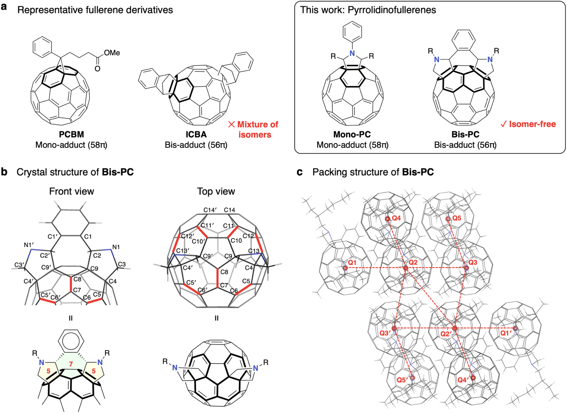 | ||
| Fig. 1 Structures of pyrrolidinofullerenes in this study. (a) Chemical structures of representative fullerene derivatives, PCBM and ICBA, and mono and bis(pyrrolidino)fullerenes, Mono-PC and Bis-PC. (b) Single crystal structure of Bis-PC. Selected bond lengths (Å): C1′–C1, 1.424(6); C1–C2, 1.534(7); C2–C9, 1.559(6); C2–N1, 1.469(6); N1–C3, 1.475(6); C3–C4, 1.550(7); C4–C9, 1.597(7); C4–C5, 1.527(7); C5–C6, 1.354(7); C6–C7, 1.479(6); C7–C8, 1.350(6); C8–C9, 1.483(6); C9–C10, 1.517(7); C10–C11, 1.375(7); C11–C12, 1.480(7); C12–C13, 1.368(7); C13–C4, 1.539(7); C10′–C10, 1.417(6); C10–C11, 1.375(7); C14′–C14, 1.400(7). (c) Packing structure of Bis-PC. Selected centroid–centroid distances (CCDs) between fullerene cages (nm): Q1–Q2, 0.984; Q2–Q3, 0.984; Q2–Q4, 1.296; Q2–Q3′, 0.995; Q2–Q2, 1.014. | ||
The formation of various isomers, depending on where the second addition occurs (cis-1 to 3, trans-1 to 4, equatorial, etc.) is a general challenge of the fullerene bisadducts. Isomer formation results in low yields of the desired product, which must be isolated by a time-consuming purification step.40,41 Wei et al. recently reported that the number of isomers can be reduced to six in the case of a diethylmalonate-C60 bisadduct (DCBA).42 They succeeded in isolating four regioisomers and found that pure isomers resulted in solar cells with higher performance than the mixture. The same group later reported that the selective synthesis of a single isomer could be achieved by temporarily adding bulky substituents to control the steric hindrance during the introduction of ethylmalonate.43 Using a supramolecular complex is another powerful method to access single-isomer bisadducts of fullerenes.44–46 Recently, our group successfully used a single-isomer open-cage bis[60]fulleroid in Sn PSCs.47
Herein, we report phenylene-bridged bis(pyrrolidino)fullerene,48,49Bis-PC, for use as an ETM in Sn PSCs (Fig. 1a). The molecular design features geometrical restrictions to induce the preferential formation of the cis-2 bisadduct. Mono(pyrrolidino)fullerene, Mono-PC, was synthesized as a reference compound to investigate how the energy level alignment affects the device performance. The effect of methylammonium (MA) incorporation into the A-site of PEA0.15FA0.85SnI3 was also studied. The combined use of the Bis-PC ETM and PEA0.15(FA0.87MA0.13)0.85SnI3 perovskite composition resulted in 3000 h shelf-stable devices with a maximum PCE of 12.3% and a VOC of 0.86 V (VOC loss of 0.51 V).
Results and discussion
Synthesis and characterization
The target bis(pyrrolidino)fullerene, Bis-PC, was synthesized in one step from C60 by the 1,3-dipolar cycloaddition of an ylide formed by the reaction of o-phthalaldehyde and N-(2-ethylhexyl)glycine.48,49 The 2-ethylhexyl group was introduced to make the compound soluble enough to use as a solution-processable ETM (>20 mg mL−1 in chlorobenzene). The mono(pyrrolidino)fullerene, Mono-PC, was synthesized by the reaction of C60 with heptanal and 2-(phenylamino)octanoic acid.50 These compounds were characterized by nuclear magnetic resonance (NMR), mass spectrometry (MS), and single-crystal X-ray structure analysis.Single crystals of Bis-PC were grown by slowly cooling the solution of Bis-PC in chlorobenzene from 70 °C to room temperature. The front and top views of the crystal structure are shown in Fig. 1b. The five-membered pyrrolidine rings adopt an envelope form, whereas the central seven-membered ring is in a twist-chair form. The fused benzene ring is bent backward towards the fullerene, with a 108° dihedral angle between the pyrrolidine rings and the benzene. As for the bond lengths, C5–C6 [1.354(7) Å] and C7–C8 [1.350(6) Å] are much shorter than C4–C5 [1.527(7) Å], C6–C7 [1.479(6) Å], C8–C9 [1.483(6) Å], and C9–C4 [1.597(7) Å]. This suggests that the diene character emerged after pyrrolidine was added to the C9–C4 bonds. Similarly, a significant bond alternation was observed where the bonds shown in red lines have a strong double bond character. These trends of the bond lengths are comparable to those of similar fullerene bisadducts.51
The molecular packing structure of Bis-PC is shown in Fig. 1c and S1.† It is reported that electrons can be transported efficiently between fullerene cages when the centroid–centroid distance (CCD) is about 1 nm.52,53 In our compound, one fullerene molecule (e.g. Q2) is surrounded by five carbon cages (e.g. Q1, Q3, Q4, Q2′, and Q3′), with CCDs of Q1–Q2 [0.984 nm], Q2–Q3 [0.984 nm], Q2–Q4 [1.296 nm], Q2–Q3′ [0.995 nm], and Q2–Q2′ [1.014 nm]. This results in an average CCD of 1.05 nm, indicating that efficient electron transport is feasible within this structure.
Basic properties
The electrochemical properties of the fullerenes were evaluated by cyclic voltammetry (CV) in o-dichlorobenzene (ODCB) (Fig. 2a). Both Mono-PC and Bis-PC exhibit two reversible reduction waves. The first reduction potential of Bis-PC (E1/2 = −1.41 V vs. Fc/Fc+) is negatively shifted compared to that of Mono-PC (E1/2 = −1.21 V) by 0.20 V, suggesting that the electron-accepting ability of Bis-PC is weaker than that of Mono-PC. The LUMO energy levels estimated from the onset of the first reduction potentials54 are −3.96 and −3.76 eV for Mono-PC and Bis-PC, comparable to those of PCBM and ICBA, respectively (Fig. 2b). The tendency of the electronic structures of the fullerene derivatives was consistent with the density functional theory (DFT) calculations (Fig. S2†). The LUMO energy levels of fullerenes were also evaluated using low-energy inverse photoelectron spectroscopy (LEIPS).55–57 To ensure the reliability of the data, the LEIPS measurements were conducted for 5, 10, and 15 nm-thick films with two wavelengths of photon detection (260 and 285 nm), and the average value was calculated (raw data in Fig. S3 and S4,† and histogram in Fig. S5†). The average LUMO energies were determined to be −3.59 ± 0.02, −3.52 ± 0.14, −3.73 ± 0.02, and −3.59 ± 0.04 eV for Mono-PC, Bis-PC, PCBM, and ICBA, respectively (Fig. 2b). These values for PCBM and ICBA are in good agreement with the previously measured values.58,59 Although the absolute values are influenced by crystallinity and orientation of molecular dipoles,60,61 the general trend of the bisadduct having higher LUMO levels than the monoadduct was confirmed, consistent with the result of cyclic voltammetry.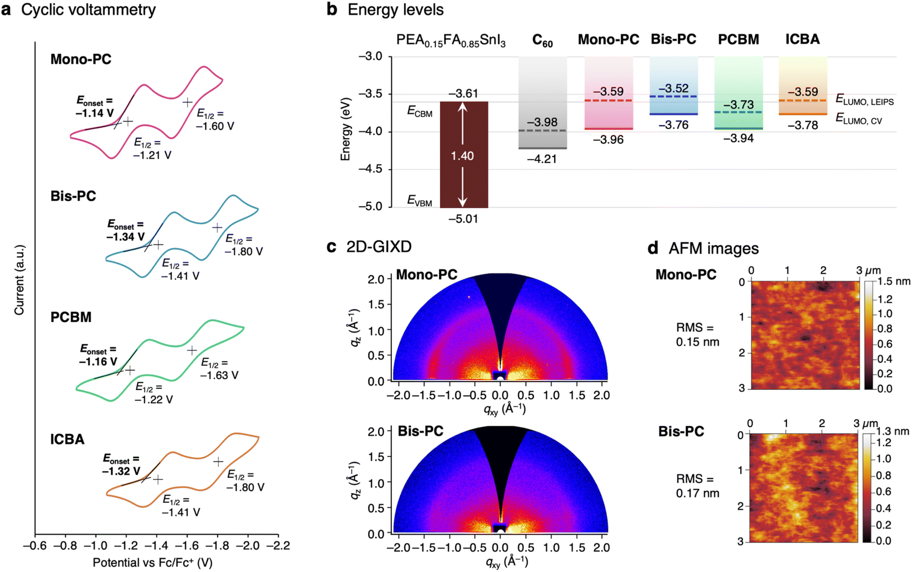 | ||
| Fig. 2 Basic properties of pyrrolidinofullerene derivatives. (a) Cyclic voltammograms of Mono-PC, Bis-PC, PCBM, and ICBA recorded in o-dichlorobenzene at a scan rate of 100 mV s−1 using n-Bu4NPF6 as the supporting electrolyte. (b) Energy level diagrams of the tin perovskite PEA0.15FA0.85SnI3 and the fullerene derivatives. The ELUMO values for C60 were taken from the previous reports.19,58 (c) Two-dimensional grazing-incidence X-ray diffraction (2D-GIXD) and (d) atomic force microscope (AFM) images for the ca. 50 nm thick thin films of Mono-PC and Bis-PC fabricated on Si substrates. | ||
The crystallinity and morphology of the films were evaluated by two-dimensional grazing-incidence X-ray diffraction (2D-GIXD) and atomic force microscopy (AFM) techniques. Thin films were prepared on Si substrates by spin-coating, using a 20 mg mL−1 solution of fullerene derivatives in chlorobenzene. The thicknesses of Mono-PC and Bis-PC films were estimated by ellipsometry to be 47.2 ± 0.1 and 49.6 ± 0.1 nm, respectively (Table S1†). The 2D-GIXD patterns of Mono-PC and Bis-PC films show no obvious Bragg diffraction, suggesting that these films are essentially amorphous (Fig. 2c). The AFM images of Mono-PC and Bis-PC films exhibit smooth surfaces with a root-mean-square (RMS) roughness of less than 0.2 nm (Fig. 2d). As reported in our previous study,62 amorphous, smooth films are ideal for ETMs to block holes completely and to prevent current leakage.
Device fabrication: comparison of ETMs
A quasi-2D/3D perovskite, PEA0.15FA0.85SnI3, was used as the light-absorbing layer for evaluating the fullerene derivatives as ETMs in inverted-type solar cell devices. The device structure is glass/ITO/PEDOT:PSS/PEA0.15FA0.85SnI3/fullerenes/bathocuproine (BCP)/Ag (Fig. 3a). The current–voltage (J–V) curves of the devices are shown in Fig. 3b, and device parameters are summarized in Table 1. The device using Mono-PC showed a PCE of 6.63% with a JSC of 18.3 mA cm−2, a VOC of 0.54 V, and a FF of 0.67 (forward scan), which is an overall higher performance than the PCBM-based device (PCE = 4.78%). The Bis-PC-based device, meanwhile, exhibited a PCE of 9.70% with a VOC of 0.78 V. The VOC of the Bis-PC-based device increased from the Mono-PC or PCBM-based device and is comparable to that of the ICBA-based device (VOC = 0.77 V). The improved VOC of the Bis-PC-based device can be ascribed to the reduced energy offset between ELUMO of the ETM and ECBM of perovskite; 0.15 eV for Bis-PC compared to 0.35 eV for Mono-PC. The integrated JSC from the external quantum efficiency (EQE) spectrum was confirmed to be similar to the values obtained from the J–V curves (Fig. S6†). The statistical distribution from 12 devices is summarized in Fig. 3c, revealing that the overall performance in terms of VOC is PCBM < Mono-PC < Bis-PC ≒ ICBA. The ICBA-based device showed higher PCE (10.4 ± 0.5%) than Bis-PC (9.1 ± 0.7%) due to the higher fill factor (0.72 ± 0.02 for ICBA and 0.64 ± 0.02 for Bis-PC). The low fill factor of Bis-PC-based devices is ascribed to the moderate electron mobility of Bis-PC (2.6 × 10⁻⁵ cm2 V−1 s−1) estimated by the space-charge limited current (SCLC) method (Fig. S7†). Fig. 3d represents the long-term stability of the devices stored under a nitrogen atmosphere. The device efficiency with mixed-isomer ICBA drops to 35% after storage for 1000 hours. In contrast, the device with single-isomer Bis-PC exhibited high stability, retaining its initial efficiency for over 3000 hours. The higher thermal stability of Bis-PC (Td5 = 361 °C) in thermogravimetric analysis (TGA) compared to ICBA (250 °C, Fig. S8†), and the higher amorphous stability of Bis-PC films up to 180 °C (Fig. S9†) are likely related to the superior shelf stability of Bis-PC-based solar cell devices.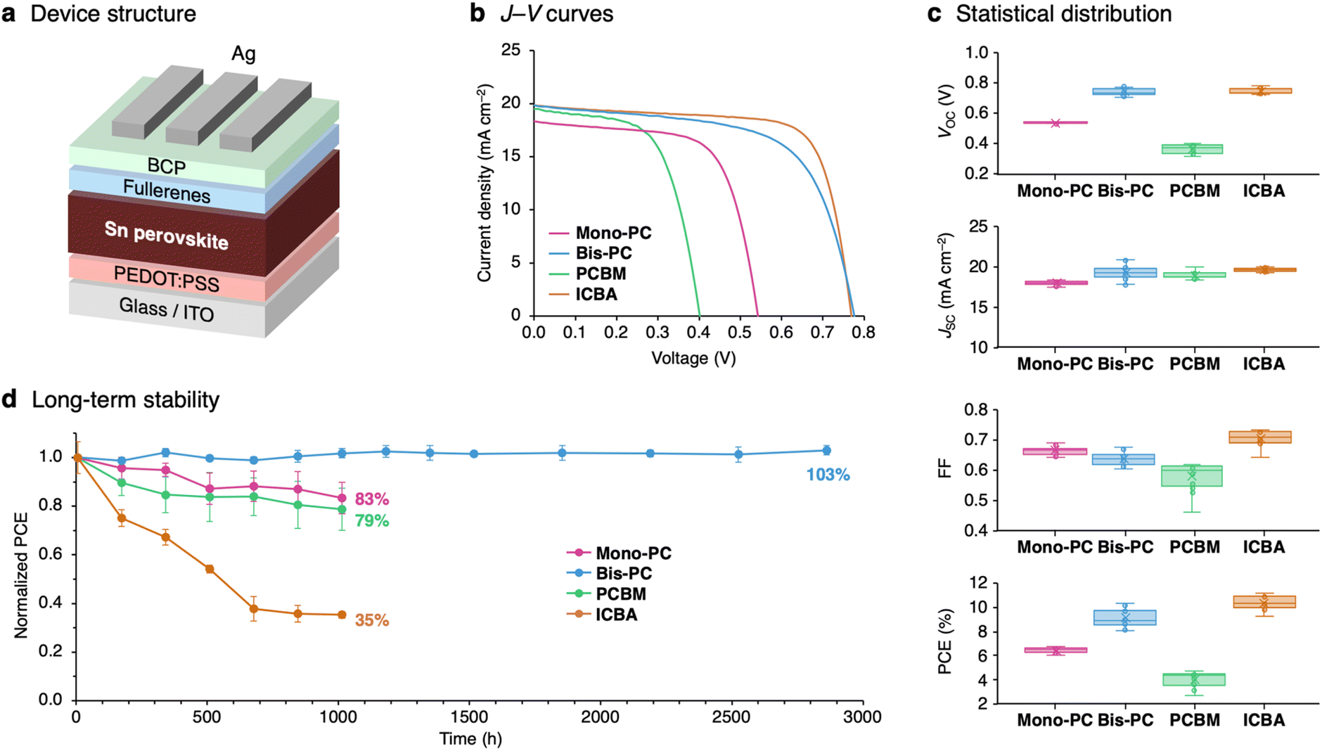 | ||
| Fig. 3 Comparison of fullerene-based electron-transporting materials. (a) Device structure and (b) current–voltage (J–V) curves of tin perovskite solar cells using different electron-transporting materials. (c) Statistical distribution of photovoltaic parameters and (d) long-term stability under nitrogen conditions. | ||
| ETM | J SC (mA cm−2) | V OC (V) | FFa | PCEa (%) |
|---|---|---|---|---|
| a The average and standard deviation values for 12 devices are given in parentheses. | ||||
| Mono-PC | 18.32 (18.2 ± 0.2) | 0.54 (0.54 ± 0.00) | 0.67 (0.66 ± 0.01) | 6.63 (6.4 ± 0.2) |
| Bis-PC | 19.85 (19.7 ± 0.6) | 0.78 (0.74 ± 0.02) | 0.63 (0.63 ± 0.01) | 9.70 (9.1 ± 0.7) |
| PCBM | 19.52 (19.2 ± 0.4) | 0.40 (0.37 ± 0.02) | 0.61 (0.59 ± 0.03) | 4.78 (4.2 ± 0.5) |
| ICBA | 19.85 (19.7 ± 0.2) | 0.77 (0.75 ± 0.02) | 0.73 (0.71 ± 0.02) | 11.18 (10.4 ± 0.5) |
Device fabrication: perovskite composition engineering
Encouraged by the high stability of the Bis-PC-based device, we envisioned that the device efficiency could be further increased by optimizing the perovskite composition. From our previous studies on FA/MA mixed tin perovskites,23,63 solar cell devices were fabricated with a perovskite composition of PEA0.15(FA1−xMAx)0.85SnI3 (x = 0.00, 0.13, 0.25, 0.50, and 1.00), where FA is replaced with different amounts of MA (cross-sectional and surface scanning-electron microscopy images shown in Fig. S10 and S11,† respectively). The systematic mixing of FA and MA was confirmed using X-ray diffraction (XRD) spectra, showing the linear decrease of the interplanar spacing (d100) with respect to the MA ratio (Fig. S12†). The J–V curves show that both JSC and VOC were improved by incorporating a small amount of MA (x = 0.13, Fig. 4a). The highest PCE of 12.27% was obtained for this fraction of MA, with a JSC of 21.69 mA cm−2, a VOC of 0.86 V, and a FF of 0.66. Further addition of MA decreased the device efficiency, with PCEs of 11.57%, 9.35%, and 4.77% for x = 0.25, 0.50, and 1.00 composition, respectively (Fig. S13 and Table S2†). The IPCE spectra show an increase in the maximum EQE value from 68% for the FA-only (x = 0.00) device to 76% for the MA-incorporated (x = 0.13) device, as well as a slight shift of the onset to a longer wavelength (Fig. 4b). The MA-incorporated (x = 0.13) device showed stable power output for 300 s under AM 1.5G illumination (Fig. S14†). The statistical distribution of the device parameters (Fig. 4c) clearly shows the increase of JSC, VOC, and PCE with the incorporation of MA (x = 0.13). The electrical impedance spectra of the MA-incorporated (x = 0.13) device show higher recombination resistance than the FA-only (x = 0.00) device (Fig. 4d for the spectra measured at 0.2 V bias, Fig. S15† for the full set of data), explaining the higher VOC observed in the J–V curves.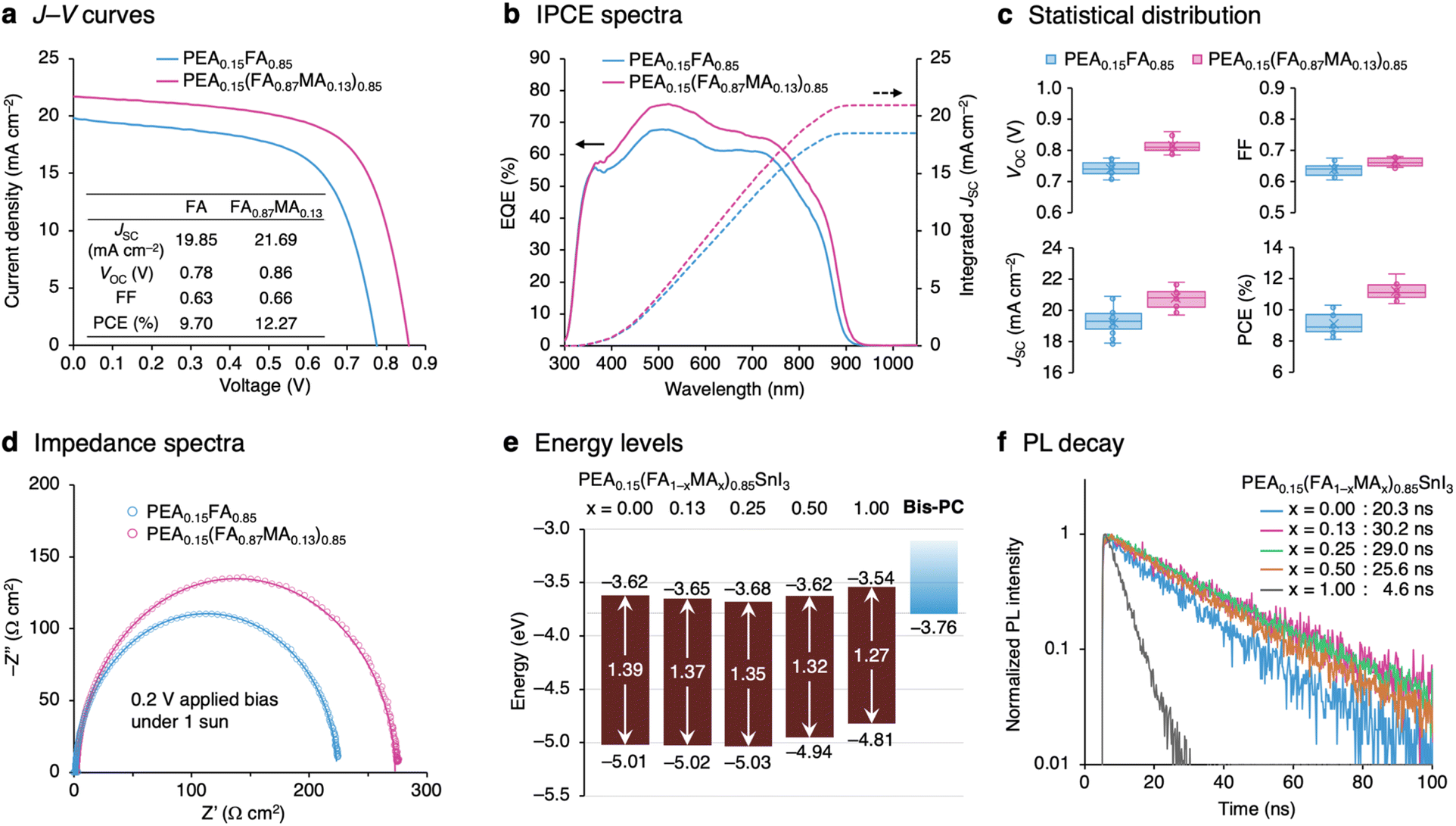 | ||
| Fig. 4 Effect of MA incorporation on the device performance. (a) J–V curves and (b) EQE spectra of tin perovskite solar cells using perovskite compositions of PEA0.15FA0.85SnI3 and PEA0.15(FA0.87MA0.13)0.85SnI3 with Bis-PC as the electron-transporting material. (c) Statistical distribution of photovoltaic parameters. (d) Electrical impedance spectra under 0.2 V applied bias and 1-sun illumination. (e) Energy level diagrams and (f) photoluminescence decay curves of PEA0.15(FA1−xMAx)0.85SnI3 (x = 0.00, 0.13, 0.25, 0.50, and 1.00) films. | ||
The device performance was evaluated at various light intensities ranging from 1 sun to 0.01 sun (Fig. S16†). The light intensity dependence of VOC is shown in Fig. S17a.† The estimated ideality factor of the MA-incorporated (x = 0.13) device (nid = 1.50) is smaller than that of the FA-only (x = 0.00) device (nid = 1.57), indicating the smaller effect of trap states.64 The fill factor of the FA-only (x = 0.00) device is maximized at the light intensity of 5 mW cm−2 (0.05 sun), whereas that of the MA-incorporated (x = 0.13) device keeps increasing as the light intensity is reduced, showing the highest FF of 0.71 under the 1 mW cm−2 (0.01 sun) irradiation (Fig. S17c†). Encouraged by the generally good performance at low light intensity, device efficiency under indoor lighting conditions was evaluated using an 800 lux white LED (0.30 mW cm−2, spectrum shown in Fig. S18b†). The MA-incorporated (x = 0.13) device showed a PCE of 13.8% with a JSC of 96.1 μA cm−2, a VOC of 0.61 V, and a FF of 0.70, which is higher than that of the FA-only (x = 0.00) device with a PCE of 9.9% (Fig. S18a†).
The MA-incorporated (x = 0.13) device also shows high long-term stability comparable to the FA-only system (x = 0.00), retaining its initial efficiency for 3000 hours (Fig. S19†). Thermostability was evaluated by repeating the process of heating the devices for one hour and measuring the J–V characteristics, increasing the temperature by 10 °C after each cycle (Fig. S20†). Both FA-only (x = 0.00) and MA-incorporated (x = 0.13) devices retained 90% of their initial performances after heating up to 90 °C.
To gain insight into how composition engineering improves device performance, the energy levels and photoluminescence (PL) properties of perovskite films were evaluated. Fig. S21a† represents the photoemission yield spectroscopy (PYS) spectra of PEA0.15(FA1−xMAx)0.85SnI3 films fabricated on glass/ITO/PEDOT:PSS substrates. Ionization energies (IEs) determined from the onset of PYS spectra were found to be almost constant until x = 0.25 (IE = 5.01, 5.02, and 5.03 eV for x = 0.00, 0.13, and 0.25 composition, respectively), and then became smaller, 4.94 eV and 4.81 eV for x = 0.50 and 1.00, respectively. The PL spectra of PEA0.15(FA1−xMAx)0.85SnI3 films are shown in Fig. S21b.† Increasing the fraction of MA caused the PL peak position to gradually shift to lower energy, from 1.39 eV for x = 0.00 to 1.27 eV for x = 1.00. The shift mirrors the change in the bandgap caused by the decrease in the average A-site radius. By adding the bandgap energy (Eg) estimated from the PL peak position to the valence band maximum energy (EVBM = −IE), the conduction band minimum (ECBM = EVBM + Eg) was estimated (Fig. 4e). It was found that compared to the FA-only (x = 0.00; ECBM = −3.62 eV) and MA-only (x = 1.00; ECBM = −3.54 eV) systems, mixing two cations causes ECBM to become deeper (ECBM = −3.65, −3.68, and −3.62 eV for x = 0.13, 0.25, and 0.50, respectively). Interestingly, a strong correlation was observed between the conduction band minimum energies and the PL lifetimes. The mixed-cation systems show longer PL lifetimes (30.2 ns, 29.0 ns, and 25.6 ns for x = 0.13, 0.25, and 0.50) compared to FA-only (x = 0.00; 20.3 ns) and MA-only (x = 1.00; 4.6 ns) systems (Fig. 4f). Long PL lifetimes observed in the mixed-cation compositions with low ECBM suggest a reduction in internal deep trap states and suppressed nonradiative recombination. Fig. S22† shows the relationship between the VOC loss from the bandgap (Eg − qVOC) and the energy level offset (ELUMO − ECB). The strong correlation of these two parameters suggests that the use of the ETM with high-lying LUMO energy and the selection of perovskite composition with low conduction band energy are important to minimize the voltage loss.
Conclusions
In summary, we synthesized a single-isomer fullerene bisadduct, phenylene-bridged bis(pyrrolidino)fullerene (Bis-PC) as well as mono(pyrrolidino)fullerene (Mono-PC), as ETMs in tin halide perovskite solar cells. Bis-PC with high-lying LUMO levels gave a higher VOC when used in PEA0.15FA0.85SnI3-based solar cell devices. More importantly, the device with single-isomer Bis-PC shows higher stability compared to that with mixed-isomer ICBA. The FA/MA-mixed PEA0.15(FA1−xMAx)0.85SnI3 system was also studied, providing a clear correlation between the lower ECBM of the perovskite composition, the longer PL lifetime, and the lower VOC loss in the solar cell device. Specifically, the device using the Bis-PC ETM and PEA0.15(FA0.87MA0.13)0.85SnI3 perovskite composition exhibited a maximum PCE of 12.3% with a VOC of 0.86 V (VOC loss of 0.51 V). Our findings offer valuable insights for further improving the efficiency and stability of tin halide perovskite solar cells.Data availability
Crystallographic data for Bis-PC have been deposited with the Cambridge Crystallographic Data Center as supplementary publication no. CCDC-2369060. These data can be obtained free of charge from the Cambridge Crystallographic Data Centre viahttps://www.ccdc.cam.ac.uk/data_request/cif.Author contributions
T. Nak. conceived the idea. T. Nak. and A. W. supervised the project. T. Nag. and Y. M. carried out the synthesis and characterization of the materials. T. Nak. conducted the X-ray structure analysis, XRD and AFM measurements, and device fabrication/characterization. Y. M. conducted the CV measurements. M. M. and H. Y. carried out the LEIPS measurements. R. M. conducted the impedance measurement. T. Nak. conducted the PL measurements with the help of T. Y. and Y. K. T. Nak. wrote the original draft of the manuscript. M. A. T., R. M., and A. W. edited the manuscript. All authors commented on the manuscript.Conflicts of interest
A. W. is co-founder and CSO of EneCoat Technologies, Co., LtdAcknowledgements
This work was partially supported by JST–Mirai (JPMJMI22E2) programs, NEDO (JPNP20015), NEDO-GI (JPNP21016), International Collaborative Research Program of ICR, Kyoto University, Grant-in-Aid for Scientific Research (A) (JP24H00481), and Grant-in-Aid for Scientific Research (B) (JP24K01571 and JP24K01607). Additional funding was provided by research grants from the Sumitomo Foundation, the Nippon Shokubai Award in Synthetic Organic Chemistry, Japan, and the JACI Prize for Encouraging Young Researcher. We thank Prof. Takeshi Hasegawa, Dr Nobutaka Shioya, and Dr Noriko Kurose (ICR, Kyoto University) for XRD measurements. We also thank Prof. Kenichiro Itami, Dr Kazuma Amaike (RIKEN), and Dr Nobutaka Honma (Toyota Motor Corporation) for fruitful discussions.Notes and references
- M. A. Green, A. Ho-Baillie and H. J. Snaith, Nat. Photonics, 2014, 8, 506–514 CrossRef CAS.
- Y. Rong, Y. Hu, A. Mei, H. Tan, M. I. Saidaminov, S. Il Seok, M. D. McGehee, E. H. Sargent and H. Han, Science, 2018, 361, eaat8235 CrossRef PubMed.
- H. J. Snaith, Nat. Mater., 2018, 17, 372–376 CrossRef CAS.
- A. K. Jena, A. Kulkarni and T. Miyasaka, Chem. Rev., 2019, 119, 3036–3103 CrossRef CAS.
- Best Research Cell Efficiencies Chart, https://www.nrel.gov/pv/assets/pdfs/best-research-cell-efficiencies.pdf, Accessed 11th December 2024.
- J. Li, H. L. Cao, W. Bin Jiao, Q. Wang, M. Wei, I. Cantone, J. Lü and A. Abate, Nat. Commun., 2020, 11, 310 CrossRef CAS.
- M. Ren, X. Qian, Y. Chen, T. Wang and Y. Zhao, J. Hazard. Mater., 2022, 426, 127848 CrossRef CAS.
- M. Konstantakou and T. Stergiopoulos, J. Mater. Chem. A, 2017, 5, 11518–11549 RSC.
- W. Ke and M. G. Kanatzidis, Nat. Commun., 2019, 10, 965 CrossRef PubMed.
- W. Ke, C. C. Stoumpos and M. G. Kanatzidis, Adv. Mater., 2019, 31, 1803230 CrossRef PubMed.
- J. Cao and F. Yan, Energy Environ. Sci., 2021, 14, 1286–1325 RSC.
- L. Xu, X. Feng, W. Jia, W. Lv, A. Mei, Y. Zhou, Q. Zhang, R. Chen and W. Huang, Energy Environ. Sci., 2021, 14, 4292–4317 RSC.
- T. Nakamura, T. Handa, R. Murdey, Y. Kanemitsu and A. Wakamiya, ACS Appl. Electron. Mater., 2020, 2, 3794–3804 CrossRef.
- E. Aktas, N. Rajamanickam, J. Pascual, S. Hu, M. H. Aldamasy, D. Di Girolamo, W. Li, G. Nasti, E. Martínez-Ferrero, A. Wakamiya, E. Palomares and A. Abate, Commun. Mater., 2022, 3, 104 CrossRef.
- S. Hu, J. A. Smith, H. J. Snaith and A. Wakamiya, Precis. Chem., 2023, 1, 69–82 CrossRef PubMed.
- W. Shockley and H. J. Queisser, J. Appl. Phys., 1961, 32, 510–519 CrossRef.
- S. Rühle, Sol. Energy, 2016, 130, 139–147 CrossRef.
- F. Gu, S. Ye, Z. Zhao, H. Rao, Z. Liu, Z. Bian and C. Huang, Sol. RRL, 2018, 2, 1800136 CrossRef.
- T. Nakamura, S. Yakumaru, M. A. Truong, K. Kim, J. Liu, S. Hu, K. Otsuka, R. Hashimoto, R. Murdey, T. Sasamori, H. Do Kim, H. Ohkita, T. Handa, Y. Kanemitsu and A. Wakamiya, Nat. Commun., 2020, 11, 3008 CrossRef PubMed.
- J. Sanchez-Diaz, R. S. Sánchez, S. Masi, M. Kreĉmarová, A. O. Alvarez, E. M. Barea, J. Rodriguez-Romero, V. S. Chirvony, J. F. Sánchez-Royo, J. P. Martinez-Pastor and I. Mora-Seró, Joule, 2022, 6, 861–883 CrossRef CAS PubMed.
- T. Nakamura, Y. Kondo, N. Ohashi, C. Sakamoto, A. Hasegawa, S. Hu, M. A. Truong, R. Murdey, Y. Kanemitsu and A. Wakamiya, Bull. Chem. Soc. Jpn., 2024, 97, uoad025 CrossRef.
- S. Shao, J. Liu, G. Portale, H. H. Fang, G. R. Blake, G. H. ten Brink, L. J. A. Koster and M. A. Loi, Adv. Energy Mater., 2018, 8, 1702019 CrossRef.
- T. Nakamura, K. Otsuka, S. Hu, R. Hashimoto, T. Morishita, T. Handa, T. Yamada, M. A. Truong, R. Murdey, Y. Kanemitsu and A. Wakamiya, ACS Appl. Energy Mater., 2022, 5, 14789–14798 CrossRef CAS.
- E. Nakanishi, R. Nishikubo, F. Ishiwari, T. Nakamura, A. Wakamiya and A. Saeki, ACS Mater. Lett., 2022, 4, 1124–1131 CrossRef CAS.
- C. Kuan, T. Liao, S. Narra, Y. Tsai, J. Lin, G. Chen and E. W. Diau, J. Phys. Chem. Lett., 2024, 15, 7763–7769 CrossRef CAS PubMed.
- S. Hu, J. Pascual, W. Liu, T. Funasaki, M. A. Truong, S. Hira, R. Hashimoto, T. Morishita, K. Nakano, K. Tajima, R. Murdey, T. Nakamura and A. Wakamiya, ACS Appl. Mater. Interfaces, 2022, 14, 56290–56297 CrossRef CAS.
- L. Wang, Q. Miao, D. Wang, M. Chen, H. Bi, J. Liu, A. K. Baranwal, G. Kapil, Y. Sanehira, T. Kitamura, T. Ma, Z. Zhang, Q. Shen and S. Hayase, Angew. Chem., Int. Ed., 2023, 62, e202307228 CrossRef CAS.
- J. Chen, J. Luo, E. Hou, P. Song, Y. Li, C. Sun, W. Feng, S. Cheng, H. Zhang, L. Xie, C. Tian and Z. Wei, Nat. Photonics, 2024, 18, 464–470 CrossRef CAS.
- Y. Shi, Z. Zhu, D. Miao, Y. Ding and Q. Mi, ACS Energy Lett., 2024, 9, 1895–1897 CrossRef.
- S. Tao, I. Schmidt, G. Brocks, J. Jiang, I. Tranca, K. Meerholz and S. Olthof, Nat. Commun., 2019, 10, 2560 CrossRef.
- T. Umeyama and H. Imahori, Acc. Chem. Res., 2019, 52, 2046–2055 CrossRef.
- Z. Xing, S. H. Li and S. Yang, Small Struct., 2022, 3, 2200012 CrossRef.
- X. Jiang, F. Wang, Q. Wei, H. Li, Y. Shang, W. Zhou, C. Wang, P. Cheng, Q. Chen, L. Chen and Z. Ning, Nat. Commun., 2020, 11, 1245 CrossRef PubMed.
- X. Jiang, H. Li, Q. Zhou, Q. Wei, M. Wei, L. Jiang, Z. Wang, Z. Peng, F. Wang, Z. Zang, K. Xu, Y. Hou, S. Teale, W. Zhou, R. Si, X. Gao, E. H. Sargent and Z. Ning, J. Am. Chem. Soc., 2021, 143, 10970–10976 CrossRef PubMed.
- B. Bin Yu, Z. Chen, Y. Zhu, Y. Wang, B. Han, G. Chen, X. Zhang, Z. Du and Z. He, Adv. Mater., 2021, 33, 2102055 CrossRef.
- T. Wang, H. L. Loi, J. Cao, Z. Qin, Z. Guan, Y. Xu, H. Cheng, M. G. Li, C. S. Lee, X. Lu and F. Yan, Adv. Sci., 2022, 9, 2200242 CrossRef.
- Z. Zhu, X. Jiang, D. Yu, N. Yu, Z. Ning and Q. Mi, ACS Energy Lett., 2022, 7, 2079–2083 CrossRef.
- W. Liu, S. Hu, J. Pascual, K. Nakano, R. Murdey, K. Tajima and A. Wakamiya, ACS Appl. Mater. Interfaces, 2023, 15, 32487–32495 CrossRef PubMed.
- Y. He, H. Y. Chen, J. Hou and Y. Li, J. Am. Chem. Soc., 2010, 132, 1377–1382 CrossRef.
- T. Cao, N. Chen, G. Liu, Y. Wan, J. D. Perea, Y. Xia, Z. Wang, B. Song, N. Li, X. Li, Y. Zhou, C. J. Brabec and Y. Li, J. Mater. Chem. A, 2017, 5, 10206–10219 RSC.
- Y. Lin, B. Chen, F. Zhao, X. Zheng, Y. Deng, Y. Shao, Y. Fang, Y. Bai, C. Wang and J. Huang, Adv. Mater., 2017, 29, 1700607 CrossRef.
- C. Sun, P. Yang, Z. Nan, C. Tian, Y. Cai, J. Chen, F. Qi, H. Tian, L. Xie, L. Meng and Z. Wei, Adv. Mater., 2023, 35, 2205603 CrossRef PubMed.
- P. Yang, C. Sun, X. Fu, S. Cheng, J. Chen, H. Zhang, Z. A. Nan, J. Yang, X. J. Zhao, L. Q. Xie, L. Meng, C. Tian and Z. Wei, J. Am. Chem. Soc., 2024, 146, 2494–2502 CrossRef PubMed.
- C. Fuertes-Espinosa, C. García-Simón, M. Pujals, M. Garcia-Borràs, L. Gómez, T. Parella, J. Juanhuix, I. Imaz, D. Maspoch, M. Costas and X. Ribas, Chem, 2020, 6, 169–186 Search PubMed.
- V. Leonhardt, S. Fimmel, A. M. Krause and F. Beuerle, Chem. Sci., 2020, 11, 8409–8415 RSC.
- E. Ubasart, O. Borodin, C. Fuertes-Espinosa, Y. Xu, C. García-Simón, L. Gómez, J. Juanhuix, F. Gándara, I. Imaz, D. Maspoch, M. von Delius and X. Ribas, Nat. Chem., 2021, 13, 420–427 CrossRef PubMed.
- W. Liu, G. Huang, C. Y. Chen, T. Tan, H. Fuyuki, S. Hu, T. Nakamura, M. A. Truong, R. Murdey, Y. Hashikawa, Y. Murata and A. Wakamiya, Chem. Commun., 2024, 60, 2172–2175 RSC.
- M. Izquierdo, M. R. Cerõn, N. Alegret, A. J. Metta-Magaña, A. Rodríguez-Fortea, J. M. Poblet and L. Echegoyen, Angew. Chem., Int. Ed., 2013, 52, 12928–12931 CrossRef.
- A. V. Mumyatov, F. A. Prudnov, D. K. Sagdullina, I. V. Martynov, L. N. Inasaridze, A. V. Chernyak, A. V. Maskaev, I. E. Kuznetsov, A. V. Akkuratov and P. A. Troshin, Synth. Met., 2021, 271, 116632 CrossRef.
- H. R. Le Sueur, J. Chem. Soc., Trans., 1910, 97, 2433–2441 RSC.
- J. Nierengarten, V. Gramlich, F. Cardullo and F. Diederich, Angew Chem. Int. Ed. Engl., 1996, 35, 2101–2103 CrossRef.
- H. Bässler, Phys. Status Solidi B, 1993, 175, 15–56 CrossRef.
- X. Sun, L. Y. Ji, W. W. Chen, X. Guo, H. H. Wang, M. Lei, Q. Wang and Y. F. Li, J. Mater. Chem. A, 2017, 5, 20720–20728 RSC.
- C. M. Cardona, W. Li, A. E. Kaifer, D. Stockdale and G. C. Bazan, Adv. Mater., 2011, 23, 2367–2371 CrossRef PubMed.
- H. Yoshida, Chem. Phys. Lett., 2012, 539–540, 180–185 CrossRef.
- H. Yoshida, Anal. Bioanal. Chem., 2014, 406, 2231–2237 CrossRef PubMed.
- H. Yoshida, J. Electron Spectros. Relat. Phenomena, 2015, 204, 116–124 CrossRef.
- H. Yoshida, J. Phys. Chem. C, 2014, 118, 24377–24382 CrossRef.
- A. Sugie, K. Nakano, K. Tajima, I. Osaka and H. Yoshida, J. Phys. Chem. Lett., 2023, 14, 11412–11420 CrossRef PubMed.
- Y. Zhong, S. Izawa, K. Hashimoto, K. Tajima, T. Koganezawa and H. Yoshida, J. Phys. Chem. C, 2015, 119, 23–28 CrossRef.
- K. Akaike, T. Kumai, K. Nakano, S. Abdullah, S. Ouchi, Y. Uemura, Y. Ito, A. Onishi, H. Yoshida, K. Tajima and K. Kanai, Chem. Mater., 2018, 30, 8233–8243 CrossRef.
- T. Nakamura, N. Shioya, T. Shimoaka, R. Nishikubo, T. Hasegawa, A. Saeki, Y. Murata, R. Murdey and A. Wakamiya, Chem. Mater., 2019, 31, 1729–1737 CrossRef.
- J. Liu, M. Ozaki, S. Yakumaru, T. Handa, R. Nishikubo, Y. Kanemitsu, A. Saeki, Y. Murata, R. Murdey and A. Wakamiya, Angew. Chem., Int. Ed., 2018, 57, 13221–13225 CrossRef PubMed.
- S. R. Cowan, A. Roy and A. J. Heeger, Phys. Rev. B, 2010, 82, 245207 CrossRef.
Footnote |
| † Electronic supplementary information (ESI) available. CCDC 2369060. For ESI and crystallographic data in CIF or other electronic format see DOI: https://doi.org/10.1039/d4sc07031c |
| This journal is © The Royal Society of Chemistry 2025 |