
 Open Access Article
 This Open Access Article is licensed under a
 Creative Commons Attribution 3.0 Unported Licence
5-Hydroxymethylfurfural (HMF) synthesis in a deep eutectic solvent-based biphasic system: closing the loop of solvent reuse, product isolation and green metrics†
Nico
Thanheuser
a,
Leonie
Schlichter
a,
Walter
Leitner
 ad,
Jesús
Esteban
*bc and
Andreas J.
Vorholt
*a
ad,
Jesús
Esteban
*bc and
Andreas J.
Vorholt
*a
aMax Planck Institute for Chemical Energy Conversion, 45470 Mülheim an der Ruhr, Germany. E-mail: andreas-j.vorholt@cec.mpg.de
bDepartment of Chemical Engineering and Materials, Faculty of Chemical Sciences, Complutense University of Madrid, Avda. Complutense s/n, Madrid 28040, Spain. E-mail: jeesteba@ucm.es; jesus.estebanserrano@manchester.ac.uk
cDepartment of Chemical Engineering, The University of Manchester, Manchester, M13 3PL, UK
dInstitute for Technical and Macromolecular Chemistry, RWTH Aachen, 52074 Aachen, Germany
First published on 19th February 2025
Abstract
The scale up and recycling of all process streams in the H4SiW12O40 catalyzed dehydration of D-fructose (Fru) to 5-hydroxymethylfurfural (HMF) were investigated. For this, a biphasic system based on a self-consuming deep eutectic solvent (DES) consisting of choline chloride (ChCl) and Fru in a molar ratio of 5![[thin space (1/6-em)]](https://www.rsc.org/images/entities/char_2009.gif) :1 as the reaction phase with in situ extraction of HMF employing acetonitrile was employed. In addition to ChCl:Fru being a cost-effective DES of renewable origin, it provides a way to suppress side reactions to levulinic and formic acid, particularly. The scale-up of the reaction system to a total volume of 180 mL resulted in a reaction time of 12.5 minutes to achieve quantitative conversion reaching high yields of 76% and selectivities as high as 83% whilst operating temperature was only at 80 °C, while proceeding twice as fast compared to the smaller scale reaction of previous work. The system shows easy separation of the upper extraction phase from the reaction phase due to the solidification of ChCl and the catalyst H4SiW12O40 upon cooling to room temperature showing partition coefficients of about 4 to 5. HMF could be isolated from the extraction phase, recovering HMF crystals of >99% purity. The system has the potential for numerous recycling runs up to a water content of 7.5 wt%, beyond which the DES phase undergoes a loss of activity due to the system transitioning to an aqueous solution. The extraction phase shows full recyclability and can be reused after simple distillation to separate HMF, showing promise for further implementation. Finally, considering the mass balance of the system, the basic green metrics of the system are calculated to show its potential compared to other similar concepts in the literature.
:1 as the reaction phase with in situ extraction of HMF employing acetonitrile was employed. In addition to ChCl:Fru being a cost-effective DES of renewable origin, it provides a way to suppress side reactions to levulinic and formic acid, particularly. The scale-up of the reaction system to a total volume of 180 mL resulted in a reaction time of 12.5 minutes to achieve quantitative conversion reaching high yields of 76% and selectivities as high as 83% whilst operating temperature was only at 80 °C, while proceeding twice as fast compared to the smaller scale reaction of previous work. The system shows easy separation of the upper extraction phase from the reaction phase due to the solidification of ChCl and the catalyst H4SiW12O40 upon cooling to room temperature showing partition coefficients of about 4 to 5. HMF could be isolated from the extraction phase, recovering HMF crystals of >99% purity. The system has the potential for numerous recycling runs up to a water content of 7.5 wt%, beyond which the DES phase undergoes a loss of activity due to the system transitioning to an aqueous solution. The extraction phase shows full recyclability and can be reused after simple distillation to separate HMF, showing promise for further implementation. Finally, considering the mass balance of the system, the basic green metrics of the system are calculated to show its potential compared to other similar concepts in the literature.
Sustainability spotlight5-Hydroxymethylfurfural (HMF) is a key building block in the development of biorefinery concepts for a more sustainable production of biofuels and bioproducts. The development of clean and effective synthetic routes to its production is crucial to reduce by-product generation. The research presented here scales-up the use of a biphasic system based on a self-consuming deep eutectic solvent for production with in situ extraction of HMF catalysed by a heteropolyacid. This system shows high solvent and catalyst recyclability with a high partition facilitating the separation of HMF and subsequent purification to 99 wt%. This work aligns with the UN sustainable development goals: affordable and clean energy (SDG 7), responsible consumption and production (SDG 12), and climate action (SDG 13). |
1. Introduction
The depletion of fossil resources may lead to a potential future shortage of carbon-based basic and platform chemicals. Replacing fossil resources with renewable resources, such as biomass, could therefore play a major role in industry in the future. In Germany, most biomass-based waste is currently composted, leaving the energy it contains unused.1 In addition, platform chemicals that are currently derived from fossil sources could also be obtained from biomass.2,3 A promising platform chemical is 5-hydroxymethylfurfural (HMF), obtained from the dehydration of bio-based carbohydrates. Due to its reactive aldehyde and alcohol groups, HMF is a suitable platform chemical for molecules such as 2,5-furandicarboxylic acid (FDCA), 2,5-bis(hydroxymethyl)furan or 2,5-dimethylfuran, which are important in the plastics, petrochemical and pharmaceutical industries.4–6 Research towards commercial processes for the production of HMF is attracting significant interest in the bioeconomy, where, additionally, new processes should consider the principles of green chemistry to minimize the risks to human health and the environment.7Scaling up the production of HMF from the laboratory to the industrial scale is fraught with a multitude of technical challenges.8 HMF is chemically unstable and prone to the formation of byproducts such as humins and hydrolysis to levulinic and formic acid in the presence of water, particularly under acidic conditions and/or at high temperatures,9 which are typical in its production process. This instability has led to numerous efforts towards the development of methods to convert HMF in a cascade to useful products.10 With the intention to obtain HMF, the use of biphasic systems for the in situ separation of HMF during reactions has widely been reported.11 Mostly, biphasic systems using water as the reaction phase (RP) have been employed, although an increasing number of efforts contemplate the use of ionic liquids and deep eutectic solvents (DESs).12
With an eye on process development, the scalability of the application and its circularity, it is crucial to consider challenging aspects that integrate the recycling of catalysts as well as the RP and extraction phases (EP) without compromising the quality or yield of HMF. In a previous study, we developed a promising laboratory scale approach to the synthesis of HMF from fructose using H4SiW12O40 as a catalyst, reaching yields as high as 80%.13 This synthesis uses a DES made from choline chloride and fructose (ChCl:Fru) with acetonitrile (MeCN) being an effective EP exhibiting high partition coefficients for the separation of HMF. Considering the renewable origin of the components of the DES as well as the potential production of aliphatic nitriles from biobased feedstock,14 this concept has great promise in the context of Green Chemistry.7 Similar systems, based on the same DES and EP but using an inorganic homogeneous acid, with slightly higher yields of about 90%, have previously been reported;15 however, the system we developed requires lower temperatures (80 vs. 100 °C) and significantly shorter reaction times (as low as 12.5 min vs. 240 min) and provides full recyclability of the EP.13
Typically, the production of HMF has been tackled at only a few mL scale to perform solvent selection and catalytic testing and screening.12 After many years of academic research, the interest in technology development for the production of HMF has transcended to industry, even at small reaction volumes,16 as displayed in Table 1. For example, BASF SE investigated the impact of different reactor operation modes (semi-batch, continuously stirred tank reactors, and pipe reactors) on the yield of HMF from Fru.17,21 Additionally, they patented a two-step continuous process using [EMIm][MeSO4]19,20 as a solvent in a monophasic system, achieving an HMF yield of up to 88%. Whilst yields are undeniably high, ionic liquids are typically costly and challenging to operate with. By way of another example, the Archer Daniels Midland Company developed various methods to optimize HMF production. Their highest yield, 80.6%, was achieved in a batch reactor using N-methyl pyrrolidone (NMP) as the solvent and Amberlyst 35 Wet as the catalyst at 115 °C for 5 h. As a general rule, the results show that HMF production takes place under relatively harsh temperature conditions (mostly above 100 °C) and at long reaction times, which translates into an energy-intensive operation.
| Company | Process type | Feedstock | Catalyst | Solvent | T [°C] | t [min] | Conversion [%] | Yield [%] | Ref. |
|---|---|---|---|---|---|---|---|---|---|
| a “—” denotes that it was not reported in the reference. | |||||||||
| BASF SE | Batch | Fructose | — | Ionic liquid, [EMIm][MeSO4] | 100–160 | 10–60 | 55–80 | 17 and 18 | |
| BASF SE | Semi-batch | Fructose | Methanesulfonic acid | Ionic liquid, [EMIm][OMs] | — | — | 97.6 | 86.5 | 19 and 20 |
| Archer Daniels Midland company | Batch | Fructose | 5% HCl | 2-Butanol + NaCl | 120 | 30 | 49 | 21 | |
| WARF | Batch | Fructose | AlCl3 + HCl | Biphasic: H2O/GVL | 170 | 20 | 94 | 84 | 22 |
| Battelle Memorial Institute | Batch | Fructose | H2SO4 | [EMIm]Cl | 80 | 180 | 99 | 80 | 23 |
| A*STAR | Batch | Fructose | HCl | Isopropanol | 120 | 60 | 82 | 24 | |
| Sartec Corp. | Continuous | Glucose | TiO2 + HCl | H2O/MIBK (1:10) |
180 | 2 | — | 46 | 25 and 26 |
| Novamont S.P.A. | Batch | Fructose | TEAB, H3PW12O40/Si50O | H2O | 80–100 | — | — | 80 | 27–29 |
| Novozymes A/S | Continuous | Fructose | Salts (e.g. KCl) | Biphasic: H2O/organic solvent | — | 98 | 70 | 30–32 | |
| Our work | Batch w/recyclable RP | Fructose | H4SiW12O40 | Biphasic | 80 | 12 | 90 | 70 | — |
| DES (ChCl:Fru)/MeCN |
|||||||||
This highlights a clear gap for the development of a reaction with an in situ extraction system that can produce high yields of HMF (a) with high selectivity in a short time, (b) under mild conditions and (c) with good product separation from the reaction medium owing to the high partition coefficients offered by the ChCl:Fru/MeCN solvent pair. Therefore, this work investigates the scale-up on a laboratory scale assessing the recyclability of the biphasic system and catalyst. In addition, we address the isolation and purification of the product from the EP via crystallization and quantify green metrics of this reaction and separation concept compared to other proposed work in the literature using non-water based biphasic systems.
2. Experimental
2.1 Materials
Choline chloride (67-48-1, ≥98%) and silico tungstic acid (12027-43-9, ≥99%) were purchased from Sigma Aldrich. D-Fructose (57-48-7, 99%) was purchased from abcr GmbH. Acetonitrile (75-05-8, ≥99.5%) and diethyl ether (60-29-7, ≥99.5%) were purchased from Carl Roth. All chemicals were used without further purification.2.2. Reaction setup and procedure
The reactions were carried out using a Büchiglasuster® Ecoclave 075 dc type 1 system (0.25 L) from Büchi AG, Switzerland. This borosilicate glass reactor has a 250 mL capacity and features a jacketed design for heating and cooling, utilizing water as the heating medium. The reactor's inner diameter measures 52 mm, while the outer jacket diameter is 125 mm, with a wall thickness of 9 mm for the reaction vessel and 5 mm for the jacket. Deflector baffles are included to prevent vortex formation during stirring. An image of the reactor setup is shown in Fig. 1. The system's product-contacting components are made of borosilicate glass, modified PTFE, or stainless steel. Stirring is achieved with an impeller or a pitched blade stirrer, powered by an IKA Eurostar 60 Control stirrer. Temperature monitoring and control are managed via a Pt100 thermocouple and an IKA HBC 10 basic thermostat. | ||
| Fig. 1 Glass reactor (Büchi) with a built-in pitched blade stirrer, a thermocouple, immersion tubes and a baffle. | ||
For a standard reaction, Fru (4.5 g, 25 mmol, 1 eq.), ChCl (18 g, 130 mmol) and 150 mL MeCN were placed in the glass reactor. The DES formed within the heat up period of the reaction mixture and therefore did not need (ex situ) performing. A small amount of Fru and 15 mL of MeCN were retained. The retained amount was used to fill the sluice with H4SiW12O40 (623 mg, 216 μmol, 0.009 eq.). To ensure the complete transfer of the catalyst into the reaction mixture, half of the retained Fru was placed into the sluice first followed by the catalyst and then by the rest of the retained Fru. After the mixture was brought up to 80 °C under constant stirring, the catalyst was added through the sluice and rinsed with the retained MeCN (15 mL). This determines the start of the reaction (t = 0). Sampling of the reaction and EPs was performed using a tube attached to a syringe, which was inserted into the liquid through a port on the top of the reactor and samples of the respective phases were taken. Stirring was stopped for the duration of the sampling to ensure phase separation. After the desired reaction time, the mixture was cooled to 20 °C, which was accelerated by adding ice to the storage container of the thermostat. To evaluate the reproducibility of the sampling of the RP, the analysis of two experiments was performed three times. In addition, for three experiments with different reaction times, the sampling of the solidified RP at 20 °C was compared with the sampling of the liquid RP at 80 °C. For experiments regarding stirrer speed, the arithmetic mean and standard deviation of the triple determinations were obtained for 400 and 600 rpm.
2.3. Solvent and catalyst recycling
After each experiment, the EP mainly consisting of MeCN was purified via rotary evaporation at 40 °C under a vacuum of 200 mbar. The water content of the distillate was determined using gas chromatography with a barrier discharge ionization detector (GC-BID). Evaporation of the EP produced a clear distillate and an oil phase as the bottom product with a brown appearance and high viscosity that wetted the vessel wall (see Fig. S1†).The reaction was started as described above, except that the catalyst was already present in the reaction mixture prior to heating. The reaction was completed 12.5 minutes after reaching 80 °C at a stirrer speed of 400 rpm. Afterwards, the reaction mixture was cooled down to 20 °C.
The EP was then removed with a tube as described in the standard procedure. Analysis was carried out with the GC-BID and MeCN was isolated from the remaining EP with the rotary evaporator. The RP was left in the reactor, to which 4.5 g Fru and ChCl were added. After the reaction 139 mL on average were recovered from the reactor. The solvent loss during the distillation was 2.8% on average, which can mainly be attributed to the transfer of the extraction phase into the various glass vessels. Detailed volumes for the workup are provided in Table S3.† The MeCN distillate was added to the reactor and filled up to 150 mL with the MeCN distillate from previous experiments to compensate for solvent loss during the workup. No change in volume of the extraction phase was observed during the recycling runs according to the calibration marks on the reactor wall. A new reaction run was then performed using the reaction conditions described above. This was repeated 3 more times. In a final experiment, a fresh RP was used and prepared with 18 g ChCl, 4.5 g Fru, and 623 mg H4SiW12O40. The distillate, which had already undergone 6 reaction cycles, was made up to 150 mL with distillate from a previous experiment and added to the reactor. The reaction conditions were the same as those in the previous experiments.
2.4. HMF purification
To recover HMF, solvent removal, extraction of the product and crystallization were conducted. MeCN was removed from the isolated EP in the rotary evaporator at a pressure of 100 mbar and temperature of 40 °C. In a separating funnel, the highly viscous sump was washed three times with 10 mL of diethyl ether. The diethyl ether containing HMF was collected in a flask. The extract was reduced to 10 mL using a rotary evaporator and then stored at −25 °C for 6 days. The liquid phase was then decanted from the flask and analyzed using the GC-BID. The crystal was dried under vacuum and subsequently analyzed by 1H-NMR spectroscopy.2.5. Analytical methods
The DES phase was analyzed with HPLC. The device used consists of modules from the Shimadzu company: an LC-20AD (pump), an SIL-20-AC (autosampler), a CTO-10ASvp (oven), a CBM-20A (control unit) and an RID-10A (refractive index detector). Furthermore, a 40 × 8 mm precolumn for organic acids and two additional columns for organic acids with a length of 30 and 10 cm and a diameter of 0.8 cm each were implemented. All columns were purchased from CS-Chromatography Service GmbH. 2 mM trifluoroacetic acid in ultrapure water solution was used as the eluent. The measurement time was set to 40 min with a flow rate of 1 mL min−1 and an injection volume of 20 μL.The EP was analyzed with a Shimadzu GC-BID 2010Plus provided with a 15 m × 0.25 mm Restek RTX-1701 column with a film thickness of 0.25 μm. The injection volume was 0.2 μL and the injection temperature was 250 °C. Helium was used as the carrier gas and the linear velocity was 30 cm s−1 with a split ratio of 30. Detection temperature was 260 °C. Before the measurement started, the oven was heated to 50 °C for 2 minutes. It was then heated to 250 °C at a rate of 25 °C min−1 maintaining the temperature for 7 min before starting the measurement. Mesitylene was used as the internal standard for the GC analysis.
The 1H-NMR spectroscopy NMR measurements to quantify the purity of HMF were carried out at 400 MHz on a Bruker Ascend 400 nuclear magnetic resonance spectrometer at 25 °C. The residual proton signal of the deuterated solvent is used as a reference for the chemical shift δ. The reference signal is labelled in the NMR spectra with the symbol #. A sample of the crystal (9.9 mg) was dissolved in deuterated chloroform and mixed with mesitylene (9.6 mg) as an internal standard.
3. Results and discussion
3.1. Mixing considerations
The small-scale experiments performed in our previous work to screen operating conditions were performed with a simple stirring bar in a total volume of about 30 mL.13 However, changing the vessel to increase the reaction volume entails a change in the surface-to-volume ratio of the dispersion to be formed and fluid dynamics, which could affect mass transfer in a multiphase system like the one being dealt with. For this reason, here it was decided to check the reaction performance using two different types of impellers: a pitched blade (Fig. 2a) and an impeller blade (Fig. 2b) stirrer, which promote axial and radial flow, respectively.33 | ||
| Fig. 2 Images of (a) the pitched blade and (b) the impeller blade used to mix the biphasic reaction system for the production of HMF. (c) Reaction performance and HMF distribution in both phases achieved with both types of impellers. Reaction conditions: 18 g ChCl, 4.5 g Fru, ChCl:Fru (5:1), Vsolvent = 150 mL, T = 80 °C, t = 15 min, ω = 600 rpm, cH4SiW12O40 = 0.87 mol%Fru. | ||
Fig. 2 shows the yields of HMF in the RP, the EP and the conversion for the two stirrer geometries considered, with the conversion being about 95% for both stirrers. The overall yield in both phases was higher with the impeller stirrer (b), reaching a value of 66%, than that with the pitched blade stirrer (a), obtaining about 54%, thus providing a higher selectivity considering the similar conversions achieved. It is assumed that the higher yield with the impeller stirrer (c) was achieved by improved mixing of the RP. This did not result in locally elevated concentrations of HMF. With the pitched blade stirrer, it is assumed that high concentrations of HMF occurred locally, resulting in increased production of high-molecular by-products such as soluble humins. For the pitched blade, an HMF distribution coefficient of 5.5 was achieved, with a somewhat lower yet similar value when an impeller blade was employed. Due to the higher selectivity for the desired product, the compromise of the lower distribution coefficient was chosen and further experiments were carried out with the impeller blade.
After selecting a mixing device, an analysis of the stirring rate was conducted to ensure operation in a regime where no mass transfer limitations exist. For this, the reaction performance and HMF partitioning were evaluated between 200 and 800 rpm. Fig. 3 shows that when the reaction was stirred at 200 rpm, the biphasic system was clearly insufficiently mixed. At this stirring rate, the lack of mixing of the catalyst in the RP leads to low conversions of 40% after 15 minutes, which may be seen in Fig. S2.† Above this layer, a yellow hue was observed indicating the formation of HMF in this part of the RP. This optical observation of the reaction is supported by the analysis of the reaction, revealing an overall yield of less than 20%. In addition, the partition coefficient reaches a value of only about 2, which is indicative of the low contact between the reaction and the EPs to promote the transfer of HMF from the former to the latter.
 | ||
| Fig. 3 Screening of the stirring speed and influence on the reaction. Reaction conditions: 18 g ChCl, 4.5 g Fru, ChCl:Fru (5:1), Vsolvent = 150 mL, T = 80 °C, t = 15 min, cH4SiW12O40 = 0.87 mol%Fru. | ||
However, stirring speeds of ≥400 rpm result in consistently high yields and selectivities, thus indicating that mixing is sufficient and that no mass transfer limitations take place. This is also underlined by constant HMF distribution in both phases. A speed of 400 rpm was chosen for further tests and shows an improvement of the reaction proceeding twice as fast compared to reactions conducted on a smaller scale.13 Despite the results presented here being obtained in a larger reaction vessel, there appears to be an agreement that only relatively low reaction rates are typically required in the production of HMF in biphasic systems to ensure that no mass transfer limitations occur.34,35
3.2. Reaction progress
An analysis of the reaction progress was carried out to assess the evolution of HMF production. Fig. 4 shows that HMF yield increases rapidly within the first half of the reaction time reaching a HMF yield of 60% with 90% selectivity after 7.5 minutes. At 15 minutes a maximum yield of 78% was achieved with a slight decrease in selectivity (83%). The reaction proceeding twice as fast compared to our published small scale reaction system13 is a significant improvement that underlines the importance of thorough mixing in a biphasic system. After 15 minutes similar values were obtained and the concentration of HMF in the RP remained constant over the course of the reaction. After 15 minutes, an average HMF distribution of 5 is achieved, but fluctuates between 4.1 and 5.8 due to the fact that small fluctuations in HMF content in the lower phase significantly influence the HMF distribution. Remarkably, a decrease in the HMF concentration due to by-product formation was not observed in these experiments, indicating HMF remaining stable in the reaction environment due to the lack of consecutive reactions. In fact, no levulinic or formic acid was detected at any time, with a sample chromatogram from these reactions being shown in Fig. S3 (GC) and S4† (HPLC). The color of both phases intensified from colorless to a yellow hue to dark yellow (Fig. S5†) over the course of the reaction indicating the formation of a small amount of humins over the course of the reaction.36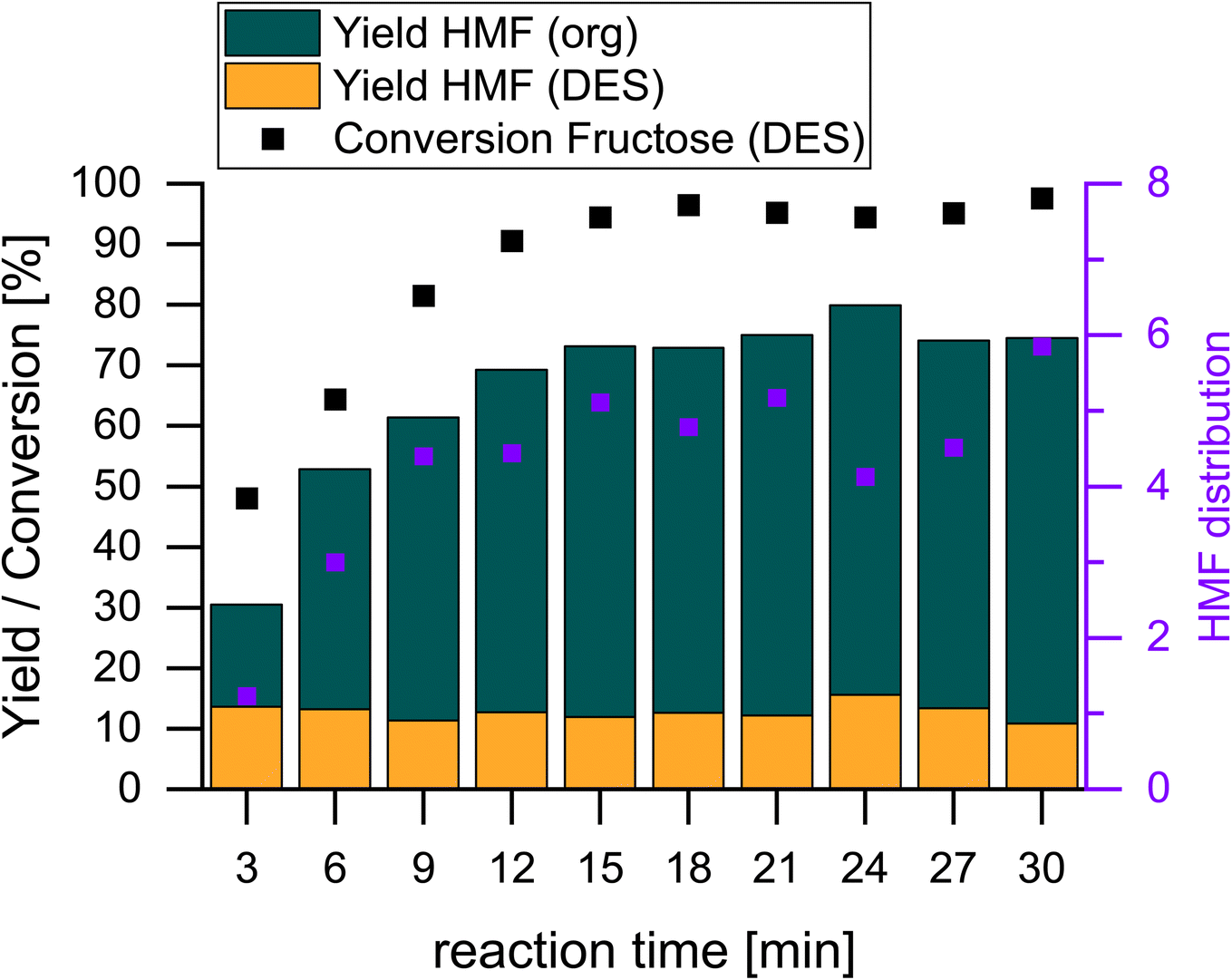 | ||
| Fig. 4 Progress of the biphasic dehydration of Fru to HMF. Reaction conditions: 18 g ChCl, 4.5 g Fru, ChCl:Fru (5:1), Vsolvent = 150 mL, T = 80 °C, t = 15 min, ω = 400 rpm, cH4SiW12O40 = 0.87 mol%Fru. | ||
As seen from the evolution of HMF presented in Fig. 4, only three samples were collected before a Fru conversion of 90% was reached at 12 minutes. A second experiment was conducted to obtain dynamic data at a higher resolution for the evolution of the amount of HMF and Fru conversion for the first 10 minutes of the reaction, as shown in Fig. 5. It can be observed that there is a linear evolution during these first moments of the reaction according to the high regression coefficients for the evolution of the concentrations of the substrate and the main product. From the linear trend, it can be inferred that the kinetics follow a zero order with respect to the concentration of the substrate and, thus, the initial reaction rates can be described by the value of an apparent reaction constant (kapp,i). Applying a simple differential method analysis, the initial reaction rates for the consumption and production of each compound (ri,0) can be approximated using the increments of the evolution of the concentrations (ΔCi) with respect to those of time (Δt), as shown in eqn (1) and (2):
 | (1) |
 | (2) |
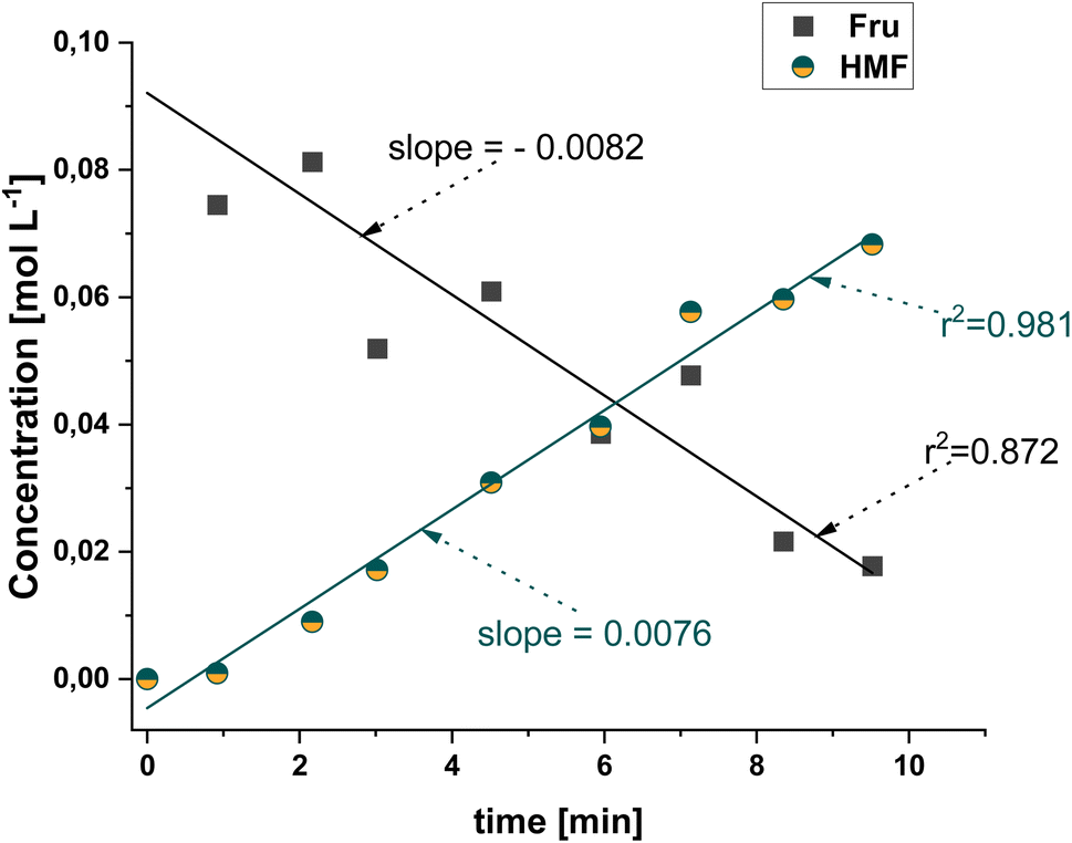 | ||
| Fig. 5 Dynamic evolution of the concentration of the substrate Fru and product HMF during the first 10 minutes of the dehydration reaction. Reaction conditions: 18 g ChCl, 4.5 g Fru, ChCl:Fru (5:1), Vsolvent = 150 mL, T = 80 °C, t = 15 min, ω = 400 rpm, cH4SiW12O40 = 0.87 mol%Fru. | ||
Analysing the values of the slope, the initial consumption rate of Fru is 0.0082 mol L−1 min−1, which is slightly higher than that of the production of HMF, at 0.0076 mol L−1 min−1. This aligns with the fact that Fru converts to HMF and another product, the humins, with a good selectivity towards the former.
3.3. Recycling of the reaction and extraction phases
To approach the circularity of the reaction and separation concept and a high overall efficiency of the process, it is crucial to recycle MeCN as the EP as well as ChCl and the H4SiW12O40 catalyst as remaining components of the RP, as depicted in Fig. 6a. For the procedure, the reaction mixture was heated to 80 °C and cooled down to room temperature after the desired reaction time. This results in the crystallization of the lower phase, which allows easy separation of the EP. After removing the EP, ChCl continued precipitating and was then fed back into the mixture to prevent any loss. After separation from the reaction medium, MeCN was then recovered from HMF via vacuum distillation and could then be recycled for the next reaction run after the addition of fresh substrate Fru to then form the self-consuming DES. Only samples from the upper phase were collected to avoid removing significant amounts of catalyst from the RP throughout the reaction, which could influence the dynamics of the system. The yield in the EP of the recycling tests is shown in Fig. 6b. A decrease in the system productivity over 5 recycling runs expressed as yield of MeCN only in the EP can be observed from 50% to 30%. Previous research demonstrated that the loss of productivity could initially mainly be attributed to water accumulation in the lower phase and potential proton leaching. However, as proven in previous work, catalyst leaching, with a maximum of 0.038% of the initial employed amount of catalyst per run, into the EP is negligible.13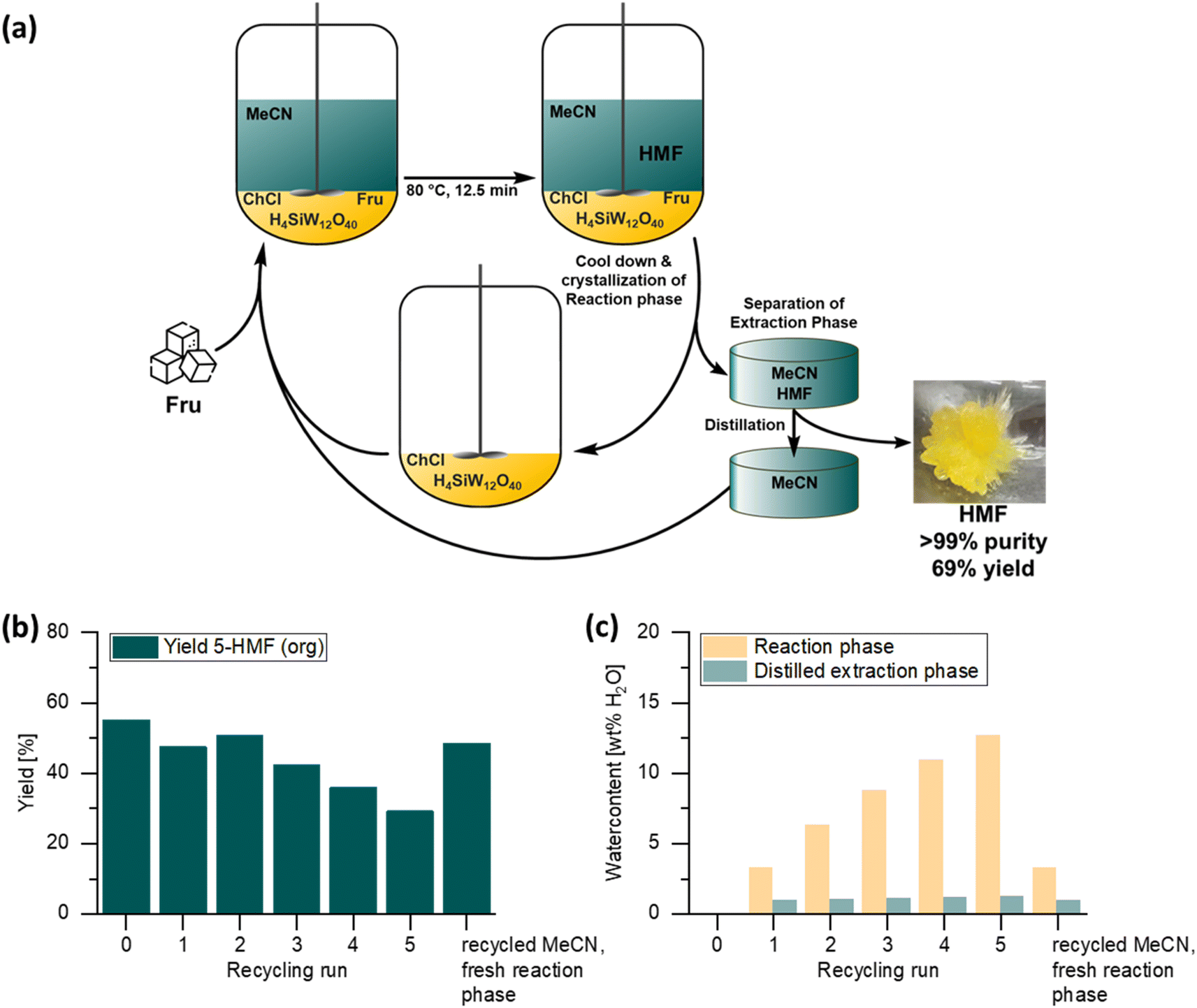 | ||
| Fig. 6 (a) Overall concept for the recyclable system for the production of HMF from Fru. (b) Yield of HMF in the EP. (c) Water content shown for both the RP and the EP reaction conditions: reaction conditions: 18 g ChCl, 4.5 g Fru, ChCl:Fru (5:1), Vsolvent = 150 mL, T = 80 °C, t = 15 min, ω = 400 rpm, cH4SiW12O40 = 0.87 mol%Fru. | ||
In addition, and quite notably, after recycling MeCN 6 times, a stable water content of about 1 wt% could be observed in this solvent, as seen in Fig. 6c. In the RP, however, the calculated water content according to the yielded HMF increased significantly over the 5 cycles, as more HMF was produced each run, but the water was not removed and thus accumulated in the RP. This also correlates with our previously identified water tolerance of this system of up to 7.5 wt% before the systems undergoes performance loss.13 Finally, to further investigate the performance of 5 times recycled MeCN, a fresh RP was prepared. This led to the restoration of the initial performance of the system, leading to the conclusion that the accumulation of water in the acetonitrile is not considered problematic for this process and the solvent can be reused repeatedly.
3.4. Product purification
The self-condensation of HMF in solution significantly accelerates the oligomerization process, particularly when acidic impurities are present.37 This instability extends even to room temperature, where HMF can exist as either a solid or a metastable liquid, depending on its melting point (30–34 °C). The liquid state, in particular, degrades more quickly due to increased molecular diffusion and residual acidity from its synthesis.36,38 This effect is more pronounced at higher concentrations of HMF and also impacts neat HMF stored in its oil form. Crystalline HMF, on the other hand, proves to be more suitable for storage and practical synthetic applications.37 To purify and obtain a more stable product, crystallization of HMF was carried out from the acetonitrile-free residue, which had been extracted with diethyl ether after distillation. After storage of the extract at −25 °C for 144 h, yellow crystals precipitated with a yellow liquid supernatant, as depicted in the photograph featured in Fig. 7. Determination by 1H NMR spectroscopy showed that the yellow crystals were HMF with a purity >99%, with the corresponding spectrum shown in the figure. A total of 409 mg of HMF crystal was recovered, which corresponds to an isolated yield of 69%. | ||
| Fig. 7 Recorded 1H-NMR spectrum of an HMF crystal dissolved in CDCl3 with mesitylene as a standard (400 MHz, * = mesitylene, # = CDCl3). | ||
3.5. Assessment of green metrics
Several key metrics exist for evaluating green chemistry and sustainability, which focus on the quantification of the waste generated, resource efficiency or solvent use, among others, in a reaction or process. These metrics provide a framework for industries such as pharmaceuticals and fine chemicals to minimize their resource use and potential environmental impact. To set out this work in perspective, a comparison with published systems of ionic liquids (ILs) and different DESs was made. For this assessment, the E-factor (environmental factor), process mass intensity (PMI), reaction mass efficiency (RME), solvent intensity (SI), and mass productivity (MP), were considered, as defined by Sheldon39 and detailed in eqn (S1)–(S5) in Table S1 in the ESI.† The E-factor and PMI offer insights into waste generation and resource use, helping to optimize processes for minimal waste and maximum material efficiency. RME refines this analysis by considering the practical performance of chemical reactions, while SI considers the mass of solvents used per unit mass of product. Mass productivity ensures that inputs are being efficiently converted into valuable products, further driving resource conservation. The results displayed in Table 2 show the results for 6 cases contemplated. The values that the calculations are based on can be found in Table S2.†| Case | RP | EP | E factor | PMI | SI | RME [%] | MP [%] | Ref. |
|---|---|---|---|---|---|---|---|---|
|
a For DESs, the ratio in brackets corresponds to the molar ratio of HBA:HBD.
b This work.
c This work with a recycled extraction phase according to Fig. 6 (only considering HMF in the extraction phase).
|
||||||||
| 1.1 | [Bmim][Cl] WCl6 | THF | 671.2 | 672.2 | 670.3 | 53.2 | 0.15 | 40 |
| 1.2 | [Bmim][Cl] WCl6 | THF | 172.1 | 173.1 | 170.2 | 38.1 | 0.58 | 40 |
| 2 | TEAC:fructose (1:0.92)a |
THF | 43.1 | 44.1 | 41.3 | 35.4 | 2.27 | 41 |
| 3 | ChCl:fructose (1:0.2)a |
MeCN | 45.6 | 46.6 | 44.9 | 59.8 | 2.15 | 15 |
| 4 | ChCl:citric acid (1:2.33)a |
EtOAc | 1708.6 | 1709.6 | 1708.1 | 64.4 | 0.06 | 42 |
| 5 | ChCl:fructose (5:1)a,b |
MeCN | 57.8 | 58.8 | 56.6 | 53.3 | 1.71 | This work |
| 6 | ChCl:fructose (5:1)a,b,c |
MeCN | 18.4 | 19.4 | 16.6 | 36.4 | 5.18 | This work |
The conversion of Fru to HMF in an ionic liquid 1-butyl-3-methylimidazolium chloride ([Bmim][Cl]) was achieved using THF as an EP with WCl6 as the catalyst. The reaction proceeded at 50 °C, the lowest temperature reported for HMF production, yielding 72%.40 The reaction, consisting of 100 mg Fru, 500 mg IL and 11 mg WCl6 catalyst, was performed in a semi batch (6 h per batch). Due to the fact that a fresh catalyst was added before run 6, only the first 5 cycles are considered for the calculation of green metrics. HMF yields that were achieved per run were 60% for the first run and around 80% for consecutive runs. Due to the high amount of THF that was used (10 mL/90 min), the E-factor, PMI and SI increased to very large numbers >600. This indicates a large production of waste/use of solvents mainly driven by the fact that no solvent recycling was performed in this work. Only the RME of 53 is in a good range, since it does not take into account the mass of solvents, which is taken into account for MP, resulting in 0.15%. According to case 1.2 this system was also investigated as a continuous reaction on a larger scale using a 2 L reaction system equipped with a solvent flow setup for simultaneous input and extraction. Initially, the system was charged with 1 L of THF, 10 g Fru, 100 grams of [Bmim][Cl], 2.2 grams of tungsten hexachloride (WCl6), and 5 grams of H–Y zeolite. Fresh THF was continuously supplied to the system at a flow rate equivalent to 4 liters every 6 hours. HMF was then recovered from THF by evaporation, allowing THF to be recycled back into the system. Due to the recycling of THF, the E-factor, PMI and SI improved to lower values between 167 and 170 and the MP from 0.15 to 0.58%. Every 6 hours, an additional 10 grams of fructose were added to the reaction mixture to sustain the reaction. After 42 hours a yield of 55% (26.7 g) was achieved. The lower overall yield led to a decrease in the RME from 53 to 38%. The ionic liquid and catalyst components of the reaction medium were reused without requiring replenishment or modification, maintaining their functionality throughout the process.
Cao et al. explored DESs as the reaction medium. The displayed example involves eutectic mixtures of tetra alkyl ammonium chloride and alkylamine hydrochloride salts, along with Fru. In these systems, the salts act as catalysts with NaHSO4 as a co-catalyst. Of the salts tested, the combination of tetraethyl ammonium chloride (TEAC) with Fru as the RP and THF as the EP produced the highest yield of 83% at 120 °C.41 They performed 14 cycles of semibatch reactions, but due to the addition of the catalyst and further modifications, only the first 8 runs are considered for the calculations of the green metrics. One batch took 30 min using 10 mL of fresh THF for the next batch. For batch 1 and 2, 1.0 g of fructose, TEAC 1.0 g, and NaHSO4·H2O 0.038 g were used. 0.50 g of fructose were added from batch runs 3 to 8. An overall yield 50% corresponding to 1.77 g HMF was achieved.
Each batch took 30 min at 120 °C, achieving HMF yields of 31% in run 1 and 50–60% for the following batches. Due to the higher Fru loading and less use of solvent, a significant improvement of the considered metrics can be observed leading to the E-factor, PMI and SI in the lower 40 range and a comparable RME to case 1 whereas the MP improved to 2.3%. If there were a recycling concept for cases 1 and 2, this would be a significant safety concern due to the fact that THF tends to form peroxides and recycling the solvent can lead to an accumulation of peroxides and therefore a risk of explosion.42 Furthermore, according to the CHEM21 solvent selection guide, THF is considered “problematic”.43
Another DES system using choline chloride (ChCl) as the hydrogen bond acceptor (HBA) and Fru as the hydrogen bond donor (HBD) in a 1:0.2 molar ratio, with acetonitrile as the EP, achieved complete Fru conversion and 90% selectivity after 4 hours at 100 °C with HCl as the catalyst.15 This system was also investigated for recyclability over 6 runs. However, it must be emphasized that only ChCl (3.6 g) was recycled, because fresh catalyst (HCl 1.2 mol% w/regard to Fru) and fresh MeCN (30 mL) were added before each run. The addition of fresh catalyst led to constant HMF yields between 87 and 92% except for the last run yielding 63%. The five-fold amount of ChCl in this case and the larger volume of EP (MeCN) have a negative impact on the green metrics, resulting in an E-factor, PMI and SI in the low 50 s. The RME is the highest with 59.8%, but the larger amount of solvent used leads to a decrease in MP to 1.9. CHEM21 has rated MeCN better than THF in terms of safety, health and environmental impact. However, after further discussion, MeCN was downgraded from “recommended” to “problematic”.43 Kobayashi et al. investigated a mixture of ChCl and citric acid as the HBD that served as both the RP and catalyst, with EtOAc forming a biphasic system. This setup showed the highest activity compared to THF, 2-BuOH, and MIBK, reaching a yield of 92%.42 Despite the high yield, the tenfold amount of solvent compared to the RP and the actual mass of HMF achieved led to inferior metrics of >1700 for the E-factor, PMI and SI. The high yields contribute to a good RME of 64.4% but due to the large amounts of solvent, the MP decreased to 0.06%. Despite the classification as “recommended” according to the CHEM21 solvent selection guide, EtOAc is an ester which, under acidic conditions, can hydrolyse to ethanol and acetic acid, both of which could act as cosolvents and disrupt the intended biphasic system.43
The system in this work considered without any recycling (case 5) already shows good green metrics as it comes out as the third best in this comparison with a slightly higher E-factor, PMI and SI and MP compared to a similar DES system in case 3. However, it should be emphasized what a significant influence our proven recycling of the EP (MeCN) has on these metrics (case 6). This leads to the best E-factor, PMI and SI between 16 and 20 for the compared systems and a second best RME of 36.4% as well as a significant increase in the MP to 5.2% making the system promising in terms of the metrics obtained thanks to its recyclability.
5 Conclusion
This work investigated the scale-up to a volume of approximately 180 mL of a biphasic reaction system for the conversion of Fru to HMF with in situ extraction catalyzed by H4SiW12O40 using ChCl:Fru (5:1) as the RP and MeCN as the EP.
First, an analysis on mixing considerations led to the selection of an impeller blade as a stirring device operating at a minimum stirring rate to ensure that no mass transfer limitations take place in the operation. From the progress of the reaction, it was observed that a remarkably low reaction time of about 12.5 min is sufficient to attain conversions of Fru greater than 90% with an overall yield of HMF of greater than 70%. During the first minutes of the reaction, a linear trend in the conversion of the substrate and the production of HMF indicate a zero-order reaction under these conditions.
An assessment of the recyclability of the biphasic system returned promising results. Concerning the RP, choline chloride could be precipitated with the catalyst, and the DES was recycled through the addition of Fru as a substrate with MeCN being recyclable with low accumulation of water after recovery by vacuum distillation. A relatively low loss of yield to HMF was observed after recycling the EP 5 times, with the initial activity of the system being recovered upon using a fresh batch of MeCN. From the separation of MeCN from HMF, the latter could then be isolated and crystallized to a purity >99%.
Finally, a comparison in terms of green metrics for this ChCl:Fru/MeCN biphasic system with 4 other cases involving DES and IL-based media reported in the literature was made. The proven recyclability of our concept stands out among the others providing the best results for the E-factor, PMI, SI, RME and MP.
In summary, the short reaction time required for the reaction to complete with high selectivity, the mild operating temperature of 80 °C, the high recyclability of the RP and EP and the results from the green metrics make this reaction concept very attractive for a techno-economic analysis for further scale-up and potential implementation.
Data availability
The data that support the findings of this study are available from the corresponding author upon reasonable request.Author contributions
Nico Thanheuser: conceptualization, methodology, validation, formal analysis, data curation, investigation, writing – original draft, visualization. Leonie Schlichter: methodology, investigation, visualization, formal analysis, Walter Leitner: conceptualization, formal analysis, resources, supervision, project administration, funding acquisition, writing – review & editing. Jesús Esteban: conceptualization, methodology, formal analysis, investigation, software, writing – original draft, writing – review & editing, supervision. Andreas J. Vorholt: conceptualization, methodology, investigation, writing – review & editing, resources, project administration, supervision, funding acquisition.Conflicts of interest
There are no conflicts to declare.Acknowledgements
The Max Planck Society (MPG) is acknowledged for funding together with the Hermann Neuhaus Foundation for awarding JE the Hermann Neuhaus Prize. JE also gratefully acknowledges grant RYC2022-035654-I funded by MICIU/AEI/10.13039/501100011033 and by ESF+ and The University of Manchester for resources.References
- Umweltbundesamt, Bioabfälle, https://www.umweltbundesamt.de/daten/ressourcen-abfall/verwertung-entsorgung-ausgewaehlter-abfallarten/bioabfaelle#bioabfalle-gute-qualitat-ist-voraussetzung-fur-eine-hochwertige-verwertung, accessed 28.09.24 Search PubMed.
- M. A. Kougioumtzis, A. Marianou, K. Atsonios, C. Michailof, N. Nikolopoulos, N. Koukouzas, K. Triantafyllidis, A. Lappas and E. Kakaras, Waste Biomass Valorization, 2018, 9, 2433–2445 CrossRef CAS.
- T. Kläusli, Green Process. Synth., 2014, 3, 235–236 CrossRef.
- W. Zhao, F. Wang, K. Zhao, X. Liu, X. Zhu, L. Yan, Y. Yin, Q. Xu and D. Yin, Carbon Resour. Convers., 2023, 6, 116–131 CrossRef CAS.
- Q. Hou, X. Qi, M. Zhen, H. Qian, Y. Nie, C. Bai, S. Zhang, X. Bai and M. Ju, Green Chem., 2021, 23, 119–231 RSC.
- R.-J. van Putten, J. C. van der Waal, E. de Jong, C. B. Rasrendra, H. J. Heeres and J. G. de Vries, Chem. Rev., 2013, 113, 1499–1597 CrossRef CAS PubMed.
- P. Anastas and N. Eghbali, Chem. Soc. Rev., 2010, 39, 301–312 RSC.
- C. Thoma, J. Konnerth, W. Sailer-Kronlachner, P. Solt, T. Rosenau and H. W. G. van Herwijnen, ChemSusChem, 2020, 13, 3544–3564 CrossRef CAS PubMed.
- A. A. Ghatta, J. D. E. T. Wilton-Ely and J. P. Hallett, ChemSusChem, 2019, 12, 4452–4460 CrossRef CAS PubMed.
- K. I. Galkin and V. P. Ananikov, ChemSusChem, 2019, 12, 185–189 CrossRef CAS PubMed.
- D. Soukup-Carne, P. López-Porfiri, F. S. Bragagnolo, C. S. Funari, X. Fan, M. González-Miquel and J. Esteban, ACS Sustainable Chem. Eng., 2024, 12, 3766–3779 CrossRef CAS PubMed.
- J. Esteban, A. J. Vorholt and W. Leitner, Green Chem., 2020, 22, 2097–2128 RSC.
- N. Thanheuser, J. T. Groteguth, W. Leitner, J. Esteban and A. J. Vorholt, ChemSusChem, 2024, e202401485 Search PubMed.
- A. Hinzmann, M. Stricker and H. Gröger, ACS Sustainable Chem. Eng., 2020, 8, 17088–17096 CrossRef CAS.
- M. Zuo, K. Le, Z. Li, Y. T. Jiang, X. H. Zeng, X. Tang, Y. Sun and L. Lin, Ind. Crops Prod., 2017, 99, 1–6 CrossRef CAS.
- C. Rosenfeld, J. Konnerth, W. Sailer-Kronlachner, P. Solt, T. Rosenau and H. W. G. van Herwijnen, ChemSusChem, 2020, 13, 3544–3564 CrossRef PubMed.
- B. Blank, A. Kindler, P. Bassler, M. Piepenbrink, O. Lang and C. Feldner, BASF SE, WO 2014199306, 2014.
- B. Blank, A. Kindler, P. Bassler, M. Piepenbrink, O. Lang and C. Feldner, BASF SE, EP 2813494A1, 2013.
- B. Blank, J. D. Hoecker, H. Werhan, J. Frank, A. Kindler, M. Piepenbrink, R. Backes and B. B. P. Staal, BASF SE, WO 2016206909A1, 2016.
- B. Blank, J. D. Hoecker, S. Son, A. Kindler, M. Piepenbrink, R. Backes and C. Feldner, BASF SE, WO 2016207365A1, 2016.
- T. R. Boussie, E. L. Dias, V. J. Murphy and J. A. W. Shoemaker, Rennovia, Archer-Daniels-Midland Company, US Pat. 10017486B2, 2018.
- J. A. Dumesic, J. M. R. Gallo and D. Alonso, Wisconsin Alumni Research Foundation, US Pat. 8772515B2, 2014.
- H. Zhao, J. Holladay and Z. C. Zhang, Batelle Memorial Institute, WO 2008019219 A1, 2008.
- Y. Zhang and L. Lai, Agency for Science, Technology and Research, US Pat. 20140357878A1, 2014.
- C. V. McNeff and D. T. Nowlan, Sartec Corporation, US Pat. 8697893B2, 2014.
- C. McNeff and D. T. Nowlan, Sartec Corporation, WO 2010075437 A2, 2010.
- C. Bastioli, L. Capuzzi, G. Carotenuto, A. D. Martino and A. Ferrari, Novamont S.P.A, US Pat. 10030001B2, 2018.
- L. Capuzzi, F. Digiola and G. Carotenuto, Novamont S.P.A, US Pat. 9409877B2, 2016.
- L. Capuzzi, F. Digioia and G. Carotenuto, Novamont S.P.A, WO 2014180979A1, 2014.
- J. S. Jensen, T. Grotkjaer, S. Pedersen and R. Ringborg, Novozymes A/S, US Pat. 20140349351A1, 2014.
- S. Pedersen, T. B. Christensen, A. Boisen, V. W. Jürgensen, T. S. Hansen, S. Kegnaes, A. Riisager, J. M. Woodley, J. S. Jensen and W. Fu, Novozymes A/S, US Pat. 8604225B2, 2013.
- S. Pedersen, T. B. Christensen, A. Boisen, V. W. Jürgensen, T. S. Hansen, S. Kegnaes, A. Riisager, J. M. Woodley, J. S. Jensen and W. Fu, Novozymes A/S, WO 2011124639 A1, 2011.
- M. Schrimpf, J. Esteban, T. Rösler, A. J. Vorholt and W. Leitner, Chem. Eng. J., 2019, 372, 917–939 CrossRef CAS.
- H. Xiang, S. Zainal, H. Jones, X. Ou, C. D'Agostino, J. Esteban, C. M. A. Parlett and X. Fan, RSC Sustainability, 2023, 1, 1530–1539 RSC.
- W. Z. Guo, Z. Zhang, J. Hacking, H. J. Heeres and J. Yue, Chem. Eng. J., 2021, 409, 128182 CrossRef CAS.
- A. Jakob, B. Likozar and M. Grilc, Green Chem., 2022, 24, 8523–8537 RSC.
- K. I. Galkin, E. A. Krivodaeva, L. V. Romashov, S. S. Zalesskiy, V. V. Kachala, J. V. Burykina and V. P. Ananikov, Angew. Chem., Int. Ed., 2016, 55, 8338–8342 CrossRef CAS PubMed.
- A. Al Ghatta, X. Zhou, G. Casarano, J. D. E. T. Wilton-Ely and J. P. Hallett, ACS Sustainable Chem. Eng., 2021, 9, 2212–2223 CrossRef CAS.
- R. A. Sheldon, ACS Sustainable Chem. Eng., 2018, 6, 32–48 CrossRef CAS.
- J. Y. G. Chan and Y. Zhang, ChemSusChem, 2009, 2, 731–734 CrossRef CAS PubMed.
- Q. Cao, X. Guo, J. Guan, X. Mu and D. Zhang, Appl. Catal., A, 2011, 403, 98–103 CrossRef CAS.
- T. Kobayashi, M. Yoshino, Y. Miyagawa and S. J. Adachi, Sep. Purif. Technol., 2015, 155, 26–31 CrossRef CAS.
- D. Prat, A. Wells, J. Hayler, H. Sneddon, C. R. McElroy, S. Abou-Shehada and P. J. Dunn, Green Chem., 2016, 18, 288–296 RSC.
Footnote |
| † Electronic supplementary information (ESI) available. See DOI: https://doi.org/10.1039/d4su00733f |
| This journal is © The Royal Society of Chemistry 2025 |