 Open Access Article
Creative Commons Attribution 3.0 Unported Licence
Reduced graphene oxide derived from the spent graphite anodes as a sulfur host in lithium–sulfur batteries†
J. Priscilla
Grace
a,
Y.
Kaliprasad
b and
Surendra K.
Martha
 *a
*a
aDepartment of Chemistry, Indian Institute of Technology Hyderabad, Kandi, Sangareddy, Telangana 502284, India. E-mail: martha@chy.iith.ac.in
bNile Limited, Lot No. 24 A/A, MLA Colony, Road No. 12, Banjara Hills, Hyderabad, India
First published on 12th November 2024
Abstract
Lithium–sulfur batteries (LSBs) offer a distinctive advantage over traditional Li-ion batteries with a higher theoretical capacity (1675 mA h g−1) and energy density (2600 W h kg−1). This study focuses on an inexpensive graphite recycled from the spent LIBs as a promising sulfur host for developing sustainable LSBs. A recycled reduced graphene oxide–sulfur (RRGO-S) composite was cast onto a 3D-carbon fiber (CF) electrode (RRGO-S@CF). The flexible and lightweight RRGO-S@CF electrodes at 500 mA g−1 delivered an initial discharge capacity of 552 mA h g−1, and there was no capacity loss in its initial five cycles, maintaining a stable capacity of 390 mA h g−1 till 300 cycles with 73% capacity retention. At a higher current density of 1.675 A g−1, it delivered an improved capacity of 417 mA h g−1. The enhanced electrochemical performance was due to the favorable interaction between the RRGO and lithium polysulfides, reducing the active material loss and polysulfide dissolution. The 3D-CF and RRGO offer a conductive network and Li-ion transport with electrolyte wettability, thereby improving the sulfur utilization and overall electrochemical performance in LSBs. This approach demonstrates the construction of recycled materials from the spent LIBs as an inexpensive source to meet the growing energy demand in the practical development of LSBs.
1. Introduction
The revolutionized lithium-ion battery technology has been commercialized in the energy market till today, although these batteries can hardly store up to 250 W h kg−1.1 Thus, it is difficult to meet today's energy demand due to their limited capacity of the cathodes (140–200 mA h g−1) and energy density. The innovative power sources are poised to redefine the future of energy storage systems.2–4 Lithium–sulfur batteries (LSBs) offer a distinctive advantage over traditional Li-ion batteries with their higher theoretical capacity (1675 mA h g−1) and energy density (2600 W h kg−1).5,6 Sulfur is the 5th most common element on earth. It is eco-friendly and inexpensive, making it an alternative energy storage electrochemical system that can reach a high energy density beyond 500 W h kg−1. Unfortunately, LSB is inherently challenging, hindering its commercialization.7 The main issue arises due to the insulating nature of sulfur, and the discharged products (Li2S) limit the utilization of sulfur. Another problem is the dissolution of polysulfides in the electrolyte that shuttle between the cathode and anode, leading to the loss of active material. Further, the volume expansion of sulfur (∼80%) causes the detachment of polysulfides from the cathode, leading to fast capacity decay during cycling and low efficiency.8–10 To overcome the shortcomings of LSBs, various carbon materials have been employed as ESI,† (host material) for sulfur cathodes to improve the electrical conductivity of sulfur by trapping the soluble polysulfides upon cycling.11,12Designing a carbon host, such as porous carbon, graphene, carbon nanotubes, and carbon nanofibers, as a conductive framework improves the electrochemical performance of LSBs. Fabrication of carbon/sulfur composite is a promising sulfur cathode design that embeds sulfur into the carbon frameworks, thus exhibiting excellent electrical conductivity and good mechanical stability.13–15 The various carbon structures exhibit excellent properties, including confining polysulfides within its matrices by avoiding the diffusion of Li2Sn in the electrolyte, reducing the loss of active materials and improving the cycle life and conductivity by providing a conductive network, and accommodating volume expansion of active materials upon cycling, which substantially benefits the electrochemical performance of LSBs.16–18
Many studies have recently focused on these materials due to the unique benefits of graphene oxide in the LSB cathode. Due to their porous network, aligned nanosheets with good electrical conductivity, high surface area, and chemical stability with oxygen-containing functional groups, the graphene oxide in the LSB cathode helps transport electrons and ions by shortening the diffusion pathways and immobilizing by suppressing the dissolution of polysulfides.19–22 Previous studies have reported that the graphene-wrapped sulfur (GWS) shows a reversible capacity of 808 mA h g−1 at 210 mA g−1 with 98% Coulombic efficiency over 100 cycles.19 Similarly, the reduced graphene oxide (RGO)-sulfur composite delivers an initial discharge capacity of 1385 mA h g−1 at 0.1C rate with 45% capacity retention for up to 100 cycles.23 A graphene-wrapped hair-derived carbon–sulfur composite delivers an initial discharge capacity of 1113 mA h g−1 at 0.2C with 89% capacity retention for up to 300 cycles.24 ESI,† Table ST1 shows a literature survey of RGO-S composite electrode electrochemical performances in terms of capacities, capacity retention, and cycle number in comparison to the present work.
The demand for graphite is continually increasing by 10–12% each year. Therefore, various carbon sources have been derived mechanistically using differing treatment strategies. Several recycling techniques have been adopted for green waste and spent LIBs electrode materials by post-treatment procedures.25 Currently, there is a progressive usage of LIBs due to the increasing energy demand. This leads to the massive disposal of LIB waste, thus resulting in environmental pollution with serious hazards.26,27 Therefore, reusing or recycling the spent LIB electrode materials is a potential approach to pave the way for better sustainable energy storage systems. A publication from our group observed that recycled graphene has a surface area of 9.12 m2 g−1 with a pore volume of 1.94 × 10⁻² cc g−1. A recycled water-washed graphite and graphene nanoflake composite had an average discharge capacity of 320 mA h g−1 over 1000 cycles with 62% capacity retention at a higher current density of 500 mA g−1.28 Recycling graphite from the inexpensive spent LIBs with cost-effective purification methods has been employed, which is expected to be successful in LIBs and the forthcoming LSBs.29
The active material sulfur content dramatically influences the enhancement of the electrochemical performance in the cathode. The low sulfur content reduces the overall energy density of LSB. The increase in the sulfur content reduces the conductivity of the electrode.30 To balance specific capacity and the cathode's stability,31,32 recycled reduced graphene oxide (RRGO) derived from LIB spent graphite anode with 3D-carbon fiber (CF) porous network architecture is employed in this work, beyond the traditional sulfur cathode, to develop RRGO-sulfur composite cathode. This electrode architecture assists in achieving stable electrochemical performance with optimal sulfur content and good capacity.33 The 3D-CF free-standing electrode is flexible and lightweight, and replaces the traditional metallic aluminum current collector.34
In this work, we report the application of a simple, effective, promising sulfur composite material on a 3D-CF as a cathode for LSB. The recycled reduced graphene oxide has been synthesized from the graphite of recycled LIBs by Hummers’ method, and the sulfur composite is obtained by melt-diffusion. The self-supported flexible RRGO-S@3D-CF electrode architecture provides fast electron and lithium ion transport, enables effective active material utilization with effective electrolyte infiltration, and accommodates volume expansion with good mechanical stability.35–37 This approach demonstrates the construction of recycled materials from the spent LIBs as an inexpensive source to meet the growing energy demand in the practical development of LSBs.
2. Experimental methods
2.1. Synthesis of recycled reduced graphene oxide (RRGO) and RRGO-sulfur composite (RRGO-S)
The commercially spent LIBs (18![[thin space (1/6-em)]](https://www.rsc.org/images/entities/char_2009.gif) 650 cells) from the laptop battery pack (supplied by our industry partner Nile Limited, Hyderabad, India) were disassembled and discharged to less than 2.0 V. The cells were dismantled manually, and the graphite from the copper foil current collector was washed with water (as water binders are used for the graphite anode), dried in a hot air oven at 100 °C for 12 h, and further heated at 750 °C in a nitrogen atmosphere to remove the organic impurities (denoted as retrieved graphite).26,28 The retrieved graphite is converted to graphene oxide by the Hummers’ method38 and thermal reduction of the retrieved graphite to reduced graphene oxide under an inert atmosphere at 500 °C for 30 min (denoted as recycled reduced graphene oxide (RRGO)).
650 cells) from the laptop battery pack (supplied by our industry partner Nile Limited, Hyderabad, India) were disassembled and discharged to less than 2.0 V. The cells were dismantled manually, and the graphite from the copper foil current collector was washed with water (as water binders are used for the graphite anode), dried in a hot air oven at 100 °C for 12 h, and further heated at 750 °C in a nitrogen atmosphere to remove the organic impurities (denoted as retrieved graphite).26,28 The retrieved graphite is converted to graphene oxide by the Hummers’ method38 and thermal reduction of the retrieved graphite to reduced graphene oxide under an inert atmosphere at 500 °C for 30 min (denoted as recycled reduced graphene oxide (RRGO)).
60% sulfur (Sigma–Aldrich) and 30% RRGO are mixed thoroughly and heated in an argon-filled Schlenk tube at 160 °C for 6 h for melt-diffusion to obtain the RRGO-S composite (ESI,† Fig. S1 and Scheme 1).
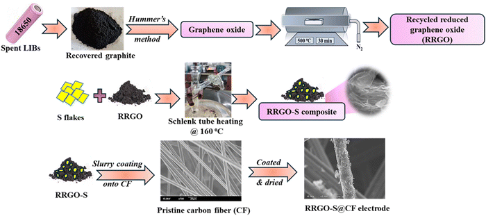 | ||
| Scheme 1 Schematic of the overall synthesis of the RRGO-S composite and the preparation of the RRGO-S@CF electrodes. | ||
2.2. Physical characterization
The physical characterization was carried out for the RRGO-S composite and RRGO-S@CF electrode. The XRD (X-ray diffraction) patterns were obtained and analyzed using a Malvern PanalyticalX'Pert3 (Netherlands) diffractometer in the 2 theta range of 10°–80°. Raman spectra were measured in a Witec Raman confocal spectrometer using a laser excitation source of 532 nm. The XPS analysis was carried out in ESCA+ (Kratos AXIS Nova, Shimadzu Japan) with the monochromic Al Kα (1486.6 eV), and it was fitted using Origin software (9.0). Morphology of the synthesized material is analyzed using a JEOL-211 (200 kV) scanning electron microscope (SEM). Thermogravimetric analysis (TGA) was conducted with a SDT Q600, Germany instrument under a nitrogen atmosphere at a heating rate of 10 °C min−1 to measure the weight loss of sulfur.2.3. Fabrication of electrodes
The slurry was prepared with 90% RRGO-S composite, 10% PVDF binder, and 1,2-N-methyl pyrrolidone (NMP) as the solvent. The slurry was coated onto CF sheets, dried, punched into 12 mm electrodes, dried further in a vacuum oven at 70 °C for 12 h, and calendered. The active material loading (sulfur) is 2 mg cm−2. Moreover, high-loading sulfur (∼4.5 mg cm−2) cells were also tested for comparison.2.4. Electrochemical characterization
As working electrodes, the RRGO-S@CF electrodes were pressed and fabricated in the CR2023 coin cell inside the glove box (O2 and H2O levels ≤ 2 ppm, mBraun). Lithium metal (10 mm diameter chip) was used as a reference and counter electrode, GF/D as a separator, and, 1 M LITFSI and DOL: DME (1![[thin space (1/6-em)]](https://www.rsc.org/images/entities/char_2009.gif) :
:![[thin space (1/6-em)]](https://www.rsc.org/images/entities/char_2009.gif) 1, V/V) with 0.1 M LiNO3 were used as the electrolyte. The galvanostatic charge–discharge cycling was carried out in a Biologic BCS-805 battery tester in the range between 1.5–2.8 V. Cyclic voltammetry (CV) and electrochemical impedance spectra (EIS) studies were conducted in the Solartron multi-channel cell test system (1470E multichannel potentiostat coupled with 1455A frequency response analyzers) at a scan rate of 0.05 mV s−1 (1.5–2.8 V) and a frequency range of 1 MHz to 0.01 Hz at a voltage perturbation of 5 mV.
1, V/V) with 0.1 M LiNO3 were used as the electrolyte. The galvanostatic charge–discharge cycling was carried out in a Biologic BCS-805 battery tester in the range between 1.5–2.8 V. Cyclic voltammetry (CV) and electrochemical impedance spectra (EIS) studies were conducted in the Solartron multi-channel cell test system (1470E multichannel potentiostat coupled with 1455A frequency response analyzers) at a scan rate of 0.05 mV s−1 (1.5–2.8 V) and a frequency range of 1 MHz to 0.01 Hz at a voltage perturbation of 5 mV.
3. Results and discussion
The XRD plot (Fig. 1a) of recycled reduced graphene shows a graphitic peak with a broad hump for the (002) plane at 24.1°. The broad hump manifests the considerable interlayer distance and the randomness of the RRGO. The RRGO-S composite synthesized by the melting-diffusion process exhibits an intense peak from 20° to 30° for the diffraction of sulfur (JCPDS no. 08-0247), confirming the orthorhombic crystal structure, which overshadowed the RRGO graphitic peaks around 24.1°. This shows that the sulfur is mainly on the surface of the amorphous layer of RRGO. The Raman spectra (Fig. 1b) of the RRGO-S composite show the D and G bands of RRGO at 1348 and 1586 cm−1, respectively, which are due to the vibration of sp2 bonded carbon atoms. However, no sulfur peaks are detected due to the masking of RRGO. The ID/IG ratio of RRGO is ∼2 (>1), depicting the disorder of the RRGO (ESI,† Fig. S3). Fig. 1c shows the Raman spectra of pure sulfur (S8) with the S–S bonds at 154, 188, 248, 439, and 474 cm−1, which matches the literature. The XRD and Raman spectra define the sulfur insertion into the RGO layers.39 The XRD pattern (ESI,† Fig. S2a) of water-washed graphite clearly shows a sharp (002) peak at 26.5° for a hexagonal crystal lattice of the graphite. The Raman spectrum (ESI,† Fig. S2b) demonstrates a flat D band at 1360 cm−1 and a G band at 1575 cm−1, and an ID/IG ratio of 0.54, thus depicting a disordered graphitic phase of the water-washed graphite.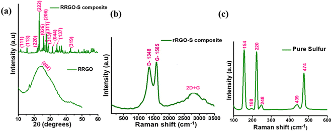 | ||
| Fig. 1 (a) XRD plots of the RRGO and RRGO-S composite. (b) and (c) Raman spectra of the RRGO-S composite and pure sulfur. | ||
The XPS analysis was carried out to understand the surface chemical compositions and elements in the RRGO-S@CF electrodes. The survey scan of RRGO-S@CF (Fig. 2a) shows the presence of the S 2p, S 2s, C 1s, and O 1s spectra. The C 1s spectra (Fig. 2b) show peaks at 284.6, 285.6, 289 and 290 eV for C–C, C–O, C![[double bond, length as m-dash]](https://www.rsc.org/images/entities/char_e001.gif) O and π–π* transition bonds in the compounds, respectively.40 The O 1s spectra (Fig. 2c) exhibit peaks at 531.9 eV and 533.6 eV for the S
O and π–π* transition bonds in the compounds, respectively.40 The O 1s spectra (Fig. 2c) exhibit peaks at 531.9 eV and 533.6 eV for the S![[double bond, length as m-dash]](https://www.rsc.org/images/entities/char_e001.gif) O and C
O and C![[double bond, length as m-dash]](https://www.rsc.org/images/entities/char_e001.gif) O bonds, respectively. The successful infusion of sulfur is manifested by the S 2p spectra, revealing peaks at 163.9, 165, 167, 168.2, and 169 eV for the S 2p3/2, S 2p1/2, S–O, and C–S bonds, respectively. The S–O bonds show sulfur oxidation with the functional groups of reduced graphene oxide. The C–S bond in O 1s and S 2p reveals the chemical bonding between the RGO and sulfur after the infusion of sulfur. The functional groups on the RRGO highly enhance the binding of sulfur in the C–C bond. The high-resolution F 1s spectra are provided in ESI,† Fig. S4. These chemical bonds show the dispersed sulfur in RRGO onto the 3D-CF electrode, thus immobilizing the dissolution of polysulfides into the electrolyte, preventing the loss of sulfur, and improving the cycling stability of the sulfur cathode (as discussed later in the electrochemistry section).
O bonds, respectively. The successful infusion of sulfur is manifested by the S 2p spectra, revealing peaks at 163.9, 165, 167, 168.2, and 169 eV for the S 2p3/2, S 2p1/2, S–O, and C–S bonds, respectively. The S–O bonds show sulfur oxidation with the functional groups of reduced graphene oxide. The C–S bond in O 1s and S 2p reveals the chemical bonding between the RGO and sulfur after the infusion of sulfur. The functional groups on the RRGO highly enhance the binding of sulfur in the C–C bond. The high-resolution F 1s spectra are provided in ESI,† Fig. S4. These chemical bonds show the dispersed sulfur in RRGO onto the 3D-CF electrode, thus immobilizing the dissolution of polysulfides into the electrolyte, preventing the loss of sulfur, and improving the cycling stability of the sulfur cathode (as discussed later in the electrochemistry section).
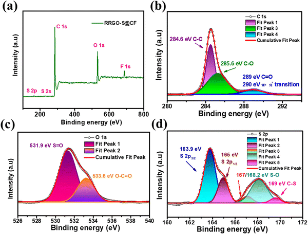 | ||
| Fig. 2 XPS of the RRGO-S@CF electrode: (a) survey scan, (b) C 1s, (c) O 1s, (d) S 2p. The binding energy was calibrated with respect to the C 1s peak of 284.6 eV. | ||
The BET surface area of CF and RRGO-S@CF is 1 m2 g−1 and 11 m2 g−1. The pore volume of CF and RRGO-S@CF is 0.008035 cm3 g−1 and 0.053174 cm3 g−1. The pore volume and adsorption–desorption curves are provided in ESI,† Fig. S5.
The SEM image of the RRGO-S composite (Fig. 3a–c) shows the graphitic layered microstructures of RRGO. Similar to the broad hump in the XRD pattern (Fig. 1a) for RRGO-S, the SEM images manifested the amorphously arranged graphene sheets along with the dispersed sulfur in the RRGO, which signifies the composite comprising both sulfur and carbon (EDAX images in ESI,† Fig. S6). The exfoliated graphene sheets not only provide a large surface area (93 m2 g−1) with more gaps, but also furnish an adsorption site for anchoring polysulfides with effective electrolyte impregnation and Li-ion transport.41 The RRGO-S slurry is coated onto the 3D-CF electrode. Fig. 3d and e shows that the composite of RRGO-S looks like a graphene sheet with sulfur adsorbed to the wall of the CF matrix, which gives a good adhesion between the active material and conductive network. As shown in Fig. 3g–i, the EDAX of RRGO-S@CF depicts the uniform dispersion of carbon and sulfur onto the CF. Therefore, the morphology result suggests that the sulfur is well dispersed in the composite and on the CF network. Fig. S6c (ESI†) shows the SEM of the water-washed graphite, displaying a smooth surface having graphite particle sizes of ∼10–20 μm (ESI,† Fig. S2d). The TGA curves of the RRGO-S (ESI,† Fig. S7) composite indicate the loss of sulfur from 160 °C to 250 °C, confirming a 60% loss of sulfur, thus manifesting a loading of sulfur (60%) in the RRGO-S composite.
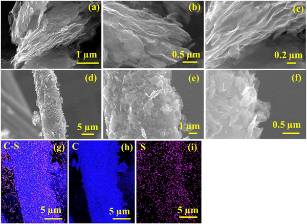 | ||
| Fig. 3 SEM image of (a)–(c) RRGO-S, (d)–(f) RRGO-S@CF, and its corresponding EDAX images: (g) C–S, (h) C and (i) S. | ||
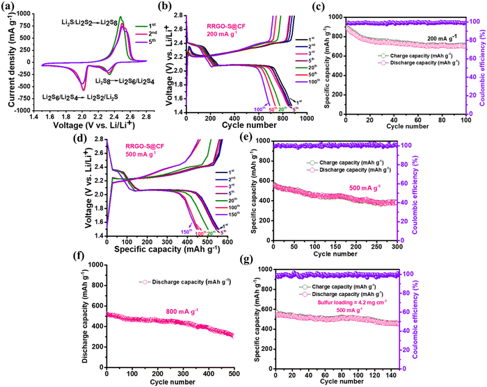
The CV plot of RRGO-S@CF (Fig. 4a) in the initial scan shows two peaks at the cathodic region around 2.34 and 2.01 V for the reduction of higher-order polysulfides (Li2S8) to soluble Li2S6/Li2S4 and the insoluble Li2S/Li2S2, and the split peak in the anodic region at 2.48 and 2.51 V is for the subsequent conversion of lithium sulfide to lithium polysulfides and to sulfur (S8). These split peaks in the anodic scan are caused by increased electrolyte viscosity due to the dissolution of polysulfides in the initial cycles. There is a slight shift in the 5th cycle due to the rearrangement of sulfur to its more stable site. The small peak shift, the high peak current under the curve, and the oxidation/reduction peaks manifest improved reversibility with improved Li-ion kinetics and the electrochemical stability of the electrode. Like the CV curves, the galvanostatic charge–discharge cycling shows two voltage plateaus in the discharge curve for the transformation of S8 to higher-order intermediate soluble polysulfides to insoluble lithium sulfides.42 The RRGO-S@CF delivers 873 mA h g−1 (Fig. 4b and c) in its 1st cycle with no negligible capacity loss in its initial five cycles, showing 774 mA h g−1 in its 20th cycle and maintaining 447 mA h g−1 for up to 100 cycles at 200 mA g−1 with 99% Coulombic efficiency. From the ESI,† in Fig. S8(a) and (b), the calculated energy densities of the 1st and the 100th cycle are 1834 and 1455 W h kg−1, respectively. Similarly, in ESI,† Fig. S8(c), the voltage hysteresis plots of the 1st and 200th cycle show that the voltage difference between the charge–discharge cycles are 0.22 and 0.18 V, respectively. The decrease in voltage in the 100th cycle (after cycling) depicts lower polarization, which suggests a smaller barrier during the efficient kinetics of the RRGO-S@CF electrodes, thus displaying a decreased resistance and an intimate contact between the RRGO and sulfur by chemical adsorption, and effectively suppressing the dissolution of polysulfides in the electrolyte during the charge–discharge cycling.43
At a current density of 500 mA g−1 (Fig. 4d and e), the initial discharge capacity is 552 mA h g−1. There is no capacity loss in their initial five cycles, showing 502 mA h g−1 in its 20th cycle. Furthermore, it maintains a stable capacity of 447 mA h g−1 for up to 150 cycles with 81% capacity retention and 73% capacity retention at the end of the 300th cycle with a Coulombic efficiency of >99%. The cyclic stability plot (Fig. 4c and e) of RRGO-S@CF (capacity vs. cycle number) also displays stable cycling for up to 100 and 300 cycles. In contrast, the RRGO-S on carbon-coated aluminum (RRGO-S@C-Al electrode) (ESI,† Fig. S9) at 500 mA g−1 delivers an initial discharge capacity of 670 mA h g−1 with 5% capacity loss in their 2nd cycle. It provides a capacity of 300 mA h g−1 (45% capacity retention) at the end of 100 cycles, which is much less compared to the stable RRGO-S@CF electrodes. Similarly, at a high current density of 800 mA g−1 (Fig. 4f), the RRGO-S@CF electrodes provide an initial discharge capacity of 535 mA h g−1 and deliver a capacity of 390 mA h g−1 even after 400 cycles with a capacity retention of 73% and 60% at the 500th cycle. Even a higher sulfur loading of ∼4.5 mg cm−2 (Fig. 4g) at 500 mA g−1 shows an initial discharge capacity of 575 mA h g−1, delivering a stable capacity of 457 mA h g−1 after 130 cycles with 99% Coulombic efficiency. Cyclic stability plots of the specific and volumetric discharge capacities at 800 mA g−1 are given in ESI,† Fig. S10. The volumetric capacities are ∼30% lower than the gravimetric capacities.
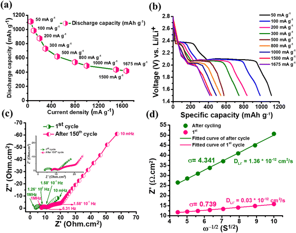
The rate capability plot of RRGO-S@CF (Fig. 5a and b) at different specific currents of 50, 100, 200, 300, 500, 800, 1000, 1500 and 1675 mA g−1 delivers excellent capacities of 1113, 985, 875, 730, 572, 540, 489, 435 and 417 mA h g−1, respectively. Even at a high specific current of 1.5 and 1.6 A g−1, the composite delivers an improved capacity of 435 and 417 mA h g−1. Upon increasing the current density, the stability of the battery also increases.44 As the specific current increases, the sulfur active material may be further activated. Thereby, the polarization effect decreases and may promote more polysulfide conversion by delivering stable capacity. The C-rate performance for the 4.5 mg cm−2 active material loading (ESI,† Fig. S11b) is demonstrated at 100, 200, 300, 500, 800, 1000 and 1500 mA g−1 specific currents, and exhibits 990, 886, 742, 580, 547, 498 and 443 mA h g−1 capacities, respectively. To understand the advantage of the RRGO-S@CF cells, a self-discharge study was performed after a fully charged condition, followed by 100 h in open circuit condition at 25 °C (ESI,† Fig. S12). The RRGO-S@CF cathode exhibits a stable OCV of ∼2.32 V during storage due to a reduction in the polysulfide shuttle effect. Before and after self-discharge, the cell maintains a capacity of 878 density and 691 mA h g−1 (20% loss of capacity), respectively (ESI,† Fig. S12b).
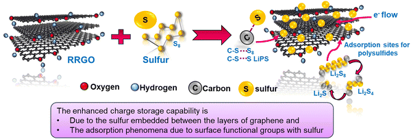
The RRGO-S@CF electrode reveals better electrochemical performance in LSBs at different current densities. The enhanced cycle performance and rate capability performance are due to the graphene network and 3D-CF, which contributes to the electronic conductivity that accelerates the ion transfer process (fast reaction kinetics), thus providing an intimate contact between the oxygen functional groups of RRGO and sulfur. Furthermore, it serves as polysulfide immobilizers by limiting the concentration of polysulfides in the electrolyte, and reduces the shuttle effect. The 3D-CF has an internal void space that offers good electrolyte infiltration, good Li-ion kinetics, and high sulfur utilization, alleviating the volume expansion. A plausible mechanism is given in the schematic shown in Scheme 2. The RGO-S composite from various literature studies, along with the capacities, capacity retention, cycle number, etc., are compared with our work (provided in ST1, ESI†).
The EIS analysis of RRGO-S@CF (Fig. 5c) for the 1st and the 150th cycle demonstrates two semicircles, which are for the high and middle-frequency regions as charge transfer resistances of sulfur intermediates, followed by the other semicircle for S8 and Li2S dissolution in the electrolyte, and the low-frequency straight line for lithium-ion diffusion (W0). The Rs and high frequency semi-circle values of the 1st cycle are 3.75 and 4 Ω cm2, respectively. For the 150th cycle, the values are 7.5 and 4 Ω cm2, respectively. The slight increase in the Rs value is due to the ohmic losses as a result of the dissolution of sulfur in the electrolyte. There is almost no change in the charge transfer resistance of the RRGO-S@CF electrode. This may be due to the better electronic conductivity of RRGO, which accelerates the electron transfer reactions during cycling. The 3D-CF effectively accommodates the volume expansion due to the Li2S formation and enhanced Li-ion kinetics by efficient electrolyte infiltration into its network, maintaining the integrity of the electrode.45 The DLi+ (lithium diffusion coefficient) can be calculated from the relationship between the Warburg impedance (W) and the inverse square root of the angular frequency (σ). The equation,  46,47 is used to calculate the value of DLi+, where R is the gas constant, T is the absolute temperature in kelvin, A is the geometrical area of the electrode in cm2, N is the number of electron transport during redox reaction, F is the Faraday's constant (96
![[thin space (1/6-em)]](https://www.rsc.org/images/entities/char_2009.gif) 500 Coulombs), C is the molar concentration of lithium ions (0.049 mol cm−3), and σ is the Warburg impedance factor. The plot of ω−1/2vs. the slope of Z′ gives the value of σ. The diffusion coefficient (Fig. 5d) value of 3 × 10⁻¹⁰ cm2 s−1 in the first cycle indicates the excellent conductivity of the RRGO-S electrode, significantly enhancing the Li-ion diffusion. The Li-ion diffusion for similar electrodes was reported in the literature to be much lower than in the current work,48 and the improved diffusion coefficient tends to enhance the electrochemical performance in terms of the cycle stability and C rate.
500 Coulombs), C is the molar concentration of lithium ions (0.049 mol cm−3), and σ is the Warburg impedance factor. The plot of ω−1/2vs. the slope of Z′ gives the value of σ. The diffusion coefficient (Fig. 5d) value of 3 × 10⁻¹⁰ cm2 s−1 in the first cycle indicates the excellent conductivity of the RRGO-S electrode, significantly enhancing the Li-ion diffusion. The Li-ion diffusion for similar electrodes was reported in the literature to be much lower than in the current work,48 and the improved diffusion coefficient tends to enhance the electrochemical performance in terms of the cycle stability and C rate.
The XPS of the post-cycled RRGO-S@CF electrode is shown in Fig. 6a. The survey scan shows the presence of Li 1s, S 2p, S 2s, C 1s, O 1s, and F 1s spectra. As indicated in Fig. 6b, the C 1s spectra show the peaks at 284.6, 283.7, 288.8, and 290.2 eV for the C–C, C–S, O–C–O, and O–C![[double bond, length as m-dash]](https://www.rsc.org/images/entities/char_e001.gif) O bonds, respectively. Fig. 6c shows the O 1s spectra, which exhibit 531, 532, and 533.4 eV peaks for the C
O bonds, respectively. Fig. 6c shows the O 1s spectra, which exhibit 531, 532, and 533.4 eV peaks for the C![[double bond, length as m-dash]](https://www.rsc.org/images/entities/char_e001.gif) O, O–S/SO42−, and O–C
O, O–S/SO42−, and O–C![[double bond, length as m-dash]](https://www.rsc.org/images/entities/char_e001.gif) O bonds, respectively. Fig. 6d shows the Li 1s spectra, where the Li–S bond at 54.6 eV is due to the chemical interaction of lithium and polysulfides and its Li2S deposition. Fig. 6e shows the S 2p spectra, which display peaks at 160.2, 161, 166.9, 167, and 168.2 eV for the Li2S, S2−, SO32−/S–O, and polythionate complex bonds, respectively. These features are attributed to the infiltration of the electrolyte during cycling.49 The S–O bonds confirm the interaction between the oxygen groups and soluble lithium polysulfides.
O bonds, respectively. Fig. 6d shows the Li 1s spectra, where the Li–S bond at 54.6 eV is due to the chemical interaction of lithium and polysulfides and its Li2S deposition. Fig. 6e shows the S 2p spectra, which display peaks at 160.2, 161, 166.9, 167, and 168.2 eV for the Li2S, S2−, SO32−/S–O, and polythionate complex bonds, respectively. These features are attributed to the infiltration of the electrolyte during cycling.49 The S–O bonds confirm the interaction between the oxygen groups and soluble lithium polysulfides.
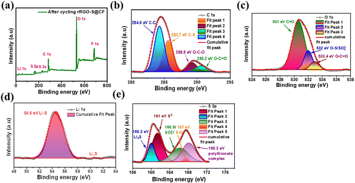 | ||
| Fig. 6 XPS of the post-cycled (after 150 cycles) RRGO-S@CF: (a) survey scan, (b) C 1s, (c) O 1s, (d) Li 1s, and (e) S 2p. | ||
The postmortem SEM images of the cycle rRGO-S@CF (Fig. 7a–c) depict the formation of lithium sulfide particles in the 3D-CF network, which is different from the before-cycling SEM of RRGO-S@CF (shown in Fig. 3a). Therefore, it manifests the integrity of the 3D-CF electrode. Furthermore, the RRGO provides a better network that prevents the polysulfides from collapsing even after cycling, which effectively accommodates the polysulfide and better Li-ion kinetics by providing sufficient electrolyte into its 3D-CF network. The formation of Li2S on the CF electrodes is depicted in the EIS after cycling (Fig. 5c), resulting in a slight increase in RCT. The EDAX (Fig. 7d–f) shows the uniform distribution of C–S, C, and S on the 3D-CF network even after cycling. Therefore, RRGO-S@CF maintains its structural integrity during the charge–discharge cycling.
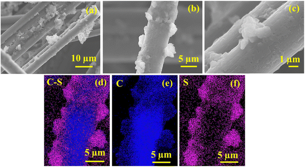 | ||
| Fig. 7 Post-cycled SEM images of the (a)–(c) cycled RRGO-S@CF electrodes and their EDAX images of (d) C–S, (e) C, and (f) S. | ||
Overall, the recycled reduced graphene oxide (RRGO) provides good conductivity that engages the electron transfer reaction and gives good accessibility for both electron and ion transfer. The oxygen functional groups contribute toward the excellent interaction with sulfur, thereby limiting the dissolution of polysulfides. The 3D-CF and RRGO offer a porous conductive network and Li-ion transport with electrolyte wettability, thereby improving the sulfur utilization and overall electrochemical performance in LSBs. This is further demonstrated in the EIS, postmortem SEM, and XPS analyses. This study describes an inexpensive graphite material recycled from the spent LIBs, which shows promise as a cathode host material for developing sustainable LSBs.
5. Conclusions
This study describes an inexpensive graphite material recycled from the spent LIBs, which will be a promising cathode host material for developing sustainable LSBs. The RRGO-S composite is synthesized by a melt-diffusion process and cast onto the 3D-CF electrode (RRGO-S@CF). At a current density of 500 mA g−1, the initial discharge capacity is 552 mA h g−1. There is no capacity loss in their initial five cycles. The material displays 502 mA h g−1 in its 20th cycle and maintains a stable capacity of 447 mA h g−1 for up to 150 cycles with 81% capacity retention and 73% capacity retention at the end of the 300th cycle. Even at a high current density of 1.675 A g−1, RRGO-S@CF delivers an improved capacity of 417 mA h g−1. Similarly, at a high current density of 800 mA g−1, the RRGO-S@CF electrodes provide an initial discharge capacity of 535 mA h g−1 and deliver a capacity of 390 mA h g−1 even after 400 cycles with a capacity retention of 73% and 60% at the 500th cycle. The enhanced electrochemical performance is due to the graphene network and 3D-CF, which contributes to the electronic conductivity that accelerates the ion transfer process (fast reaction kinetics). The material provides a favorable interaction between the RRGO and lithium polysulfides, thus reducing the active material loss and polysulfide dissolution. The 3D-CF has an internal void space that offers good electrolyte infiltration, good Li-ion kinetics, and high sulfur utilization, alleviating the volume expansion. This approach demonstrates the construction of recycled materials from the spent LIBs as an inexpensive source to meet the growing energy demand in the practical development of LSBs.Data availability
The primary research works were carried out by us without using any public data. Some of the data supporting this article have been included as part of the ESI,† and are available upon reasonable request from the authors.Conflicts of interest
There are no conflicts to declare.Acknowledgements
Dr J. Priscilla Grace acknowledges DST-INSPIRE (code: IF 190016), Govt. of India, for the fellowship. Professor Surendra K. Martha acknowledges Greenco School of Sustainability, IIT Hyderabad, for the project Reference # GSS/IITH/02/2024-25/03 “Development and Realization of High Energy Lithium-based Rechargeable Batteries for Electric Vehicles” for financial support of the work. The authors thank Dr Madhushri Bhar for the valuable help with RRGO synthesis and Khamrul Islam Nadaf for help throughout the experiments.References
- K. Zhu, C. Wang, Z. Chi, F. Ke, Y. Yang, A. Wang, W. Wang and L. Miao, Front. Energy Res., 2019, 7, 123 CrossRef
.
- Z. Yang, J. Zhang, M. C. W. Kintner-Meyer, X. Lu, D. Choi, J. P. Lemmon and J. Liu, Chem. Rev., 2011, 111, 3577–3613 CrossRef CAS PubMed
.
- E. M. Erickson, F. Schipper, T. R. Penki, J.-Y. Shin, C. Erk, F.-F. Chesneau, B. Markovsky and D. Aurbach, J. Electrochem. Soc., 2017, 164, A6341 CrossRef CAS
.
- P. Slater and E. Kendrick, J. Power Sources, 2023, 588, 233710 CrossRef
.
- A. Manthiram, S.-H. Chung and C. Zu, Adv. Mater., 2015, 27, 1980–2006 CrossRef CAS
.
- L. Carbone, S. G. Greenbaum and J. Hassoun, Sustainable Energy Fuels, 2017, 1, 228–247 RSC
.
- D. Aurbach, J. Electrochem. Soc., 2018, 165, Y1 CrossRef CAS
.
- M. Zhao, B.-Q. Li, X.-Q. Zhang, J.-Q. Huang and Q. Zhang, ACS Cent. Sci., 2020, 6, 1095–1104 CrossRef CAS
.
- A. Manthiram, Y. Fu and Y.-S. Su, Acc. Chem. Res., 2013, 46, 1125–1134 CrossRef CAS
.
- D. Moy, A. Manivannan and S. R. Narayanan, J. Electrochem. Soc., 2014, 162, A1 CrossRef
.
- F. Li, Q. Liu, J. Hu, Y. Feng, P. He and J. Ma, Nanoscale, 2019, 11, 15418–15439 RSC
.
- Y. Wang, R. Zhang, J. Chen, H. Wu, S. Lu, K. Wang, H. Li, C. J. Harris, K. Xi, R. V. Kumar and S. Ding, Adv. Energy Mater., 2019, 9, 1900953 CrossRef
.
- Z. Ma, F. Jing, Y. Fan, J. Li, Y. Zhao and G. Shao, J. Alloys Compd., 2019, 789, 71–79 CrossRef CAS
.
- W. Jan, A. D. Khan, F. J. Iftikhar and G. Ali, J. Energy Storage, 2023, 108559 CrossRef
.
- X. Ji, K. T. Lee and L. F. Nazar, Nat. Mater., 2009, 8, 500–506 CrossRef CAS PubMed
.
- Y. Wang, B. Liu, W. Zhang, C. Shao, D. Lan, X. Qu, R. Chen, W. Zhang, W. Zhao, J. Liu, Y. Zhang and Z. Shi, SN Appl. Sci., 2020, 2, 1276 CrossRef CAS
.
- Z. Li, Y. Huang, L. Yuan, Z. Hao and Y. Huang, Carbon, 2015, 92, 41–63 CrossRef CAS
.
- S. Evers and L. F. Nazar, Acc. Chem. Res., 2013, 46, 1135–1143 CrossRef CAS PubMed
.
- X. Gao, J. Li, D. Guan and C. Yuan, ACS Appl. Mater. Interfaces, 2014, 6, 4154–4159 CrossRef CAS
.
- T. Yang, J. Xia, Z. Piao, L. Yang, S. Zhang, Y. Xing and G. Zhou, ACS Nano, 2021, 15, 13901–13923 CrossRef CAS
.
- T. Long, F. Meng, B. Xu, Y. Zhao, W. Liu, X. Wei, L. Zheng and J. Liu, Sustainable Energy Fuels, 2020, 4, 3926–3933 RSC
.
- Z. Zhu, Y. Zeng, Z. Pei, D. Luan, X. Wang and X. W. (David) Lou, Angew. Chem., Int. Ed., 2023, 62, e202305828 CrossRef PubMed
.
- W. Ahn, D. U. Lee, H. S. Song, S.-H. Yeon, K.-B. Kim and Z. Chen, RSC Adv., 2015, 5, 29370–29374 RSC
.
- M. Yu, R. Li, Y. Tong, Y. Li, C. Li, J.-D. Hong and G. Shi, J. Mater. Chem. A, 2015, 3, 9609–9615 RSC
.
- M. Bhar, S. Ghosh, S. Krishnamurthy, Y. Kaliprasad and S. K. Martha, RSC Sustainability, 2023, 1, 1150–1167 RSC
.
- U. Bhattacharjee, M. Bhar, S. Bhowmik and S. K. Martha, Sustainable Energy Fuels, 2023, 7, 2104–2116 RSC
.
- S. Ghosh, M. Bhar, U. Bhattacharjee, K. Prasad Yalamanchili, S. Krishnamurthy and S. K. Martha, J. Mater. Chem. A, 2024, 12, 11362–11377 RSC
.
- M. Bhar, U. Bhattacharjee, D. Sarma, S. Krishnamurthy, K. Yalamanchili, A. Mahata and S. K. Martha, ACS Appl. Mater. Interfaces, 2023, 15, 26606–26618 CrossRef CAS
.
- Y. Luo, F. Xu, L. Sun, Y. Xia, Y. Yao, Y. Guan, S. Fang, H. Hu, C. Zhang and R. Cheng, J. Energy Storage, 2024, 85, 111067 CrossRef
.
- J. Wang, G. Yang, J. Chen, Y. Liu, Y. Wang, C. Lao, K. Xi, D. Yang, C. J. Harris, W. Yan, S. Ding and R. V. Kumar, Adv. Energy Mater., 2019, 9, 1902001 CrossRef CAS
.
- Y. Zhao, Y. Zhang, Z. Bakenova and Z. Bakenov, Front. Energy Res., 2015, 3, 1–6 Search PubMed
.
- Y. Hu, W. Chen, T. Lei, Y. Jiao, J. Huang, A. Hu, C. Gong, C. Yan, X. Wang and J. Xiong, Adv. Energy Mater., 2020, 10, 2000082 CrossRef CAS
.
- K. Balakumar and N. Kalaiselvi, RSC Adv., 2015, 5, 34008–34018 RSC
.
- N. He, L. Zhong, M. Xiao, S. Wang, D. Han and Y. Meng, Sci. Rep., 2016, 6, 33871 CrossRef CAS
.
- J. P. Grace, M. Bhar, S. Ghosh and S. K. Martha, J. Alloys Compd., 2023, 969, 172341 CrossRef CAS
.
- J. P. Grace, S. Ghosh, M. Bhar and S. K. Martha, J. Electrochem. Soc., 2024, 171, 010509–010519 CrossRef CAS
.
- S. Zhao, R. Fang, Z. Sun, S. Wang, J. Veder, M. Saunders, H. Cheng, C. Liu, S. P. Jiang and F. Li, Small Methods, 2018, 2, 1800067 CrossRef
.
- W. S. Hummers and R. E. Offeman, J. Am. Chem. Soc., 1958, 80, 1339 CrossRef CAS
.
- L. Qiang Lu, L. Jie Lu and Y. Wang, J. Mater. Chem. A, 2013, 1, 9173–9181 RSC
.
- X. Yang, R. Li, J. Yang, H. Liu, T. Luo, X. Wang and L. Yang, Carbon, 2022, 199, 215–223 CrossRef CAS
.
- Q. Xu, Y. Wang, X. Shi, Y. Zhong, Z. Wu, Y. Song, G. Wang, Y. Liu, B. Zhong and X. Guo, Green Chem., 2021, 23, 942–950 RSC
.
- Z. Deng, L. Sun, Y. Sun, C. Luo, Q. Zhao and K. Yan, RSC Adv., 2019, 9, 32826–32832 RSC
.
- Y. Liu, M. Yao, L. Zhang and Z. Niu, J. Energy Chem., 2019, 38, 199–206 CrossRef
.
- S. Choudhury, M. Zeiger, P. Massuti-Ballester, S. Fleischmann, P. Formanek, L. Borchardt and V. Presser, Sustainable Energy Fuels, 2017, 1, 84–94 RSC
.
- X. Liu, Z. Xiao, C. Lai, S. Zou, M. Zhang, K. Liu, Y. Yin, T. Liang and Z. Wu, J. Mater. Sci. Technol., 2020, 48, 84–91 CrossRef CAS
.
- F. Xie, C. Xu, Y. Liang, Z. Tian, C. Ma, S. Xu, Z. Li, Z. U. Rehman and S. Yao, J. Energy Storage, 2023, 72, 108712 CrossRef
.
- S. Ghosh, V. K. Kumar, S. K. Kumar, S. Biswas and S. K. Martha, Electrochim. Acta, 2019, 316, 69–78 CrossRef CAS
.
- H. Yu, M. Bi, C. Zhang, T. Zhang, X. Zhang, H. Liu, J. Mi, X. Shen and S. Yao, Electrochim. Acta, 2022, 428, 140908 CrossRef CAS
.
- L. Ji, M. Rao, H. Zheng, L. Zhang, Y. Li, W. Duan, J. Guo, E. J. Cairns and Y. Zhang, J. Am. Chem. Soc., 2011, 133, 18522–18525 CrossRef CAS PubMed
.
Footnote |
| † Electronic supplementary information (ESI) available. See DOI: https://doi.org/10.1039/d4ya00480a |
| This journal is © The Royal Society of Chemistry 2025 |

