Multiple excitation nano-spot generation and confocal detection for far-field microscopy
Partha Pratim
Mondal
*a
aBiological Engineering, Massachusetts Institute of Technology, Cambridge, MA 02139, USA. E-mail: partham@mit.edu
bDepartment of Instrumentation, Indian Institute of Science, Bangalore 560012, India. E-mail: partha@isu.iisc.ernet.in
First published on 9th February 2010
Abstract
An imaging technique is developed for the controlled generation of multiple excitation nano-spots for far-field microscopy. The system point spread function (PSF) is obtained by interfering two counter-propagating extended depth-of-focus PSF (DoF-PSF), resulting in highly localized multiple excitation spots along the optical axis. The technique permits (1) simultaneous excitation of multiple planes in the specimen; (2) control of the number of spots by confocal detection; and (3) overcoming the point-by-point based excitation. Fluorescence detection from the excitation spots can be efficiently achieved by Z-scanning the detector/pinhole assembly. The technique complements most of the bioimaging techniques and may find potential application in high resolution fluorescence microscopy and nanoscale imaging.
The system point spread function (PSF) of an imaging system fundamentally determines the resolution and plays a key role in qualitative imaging. However, most of the imaging components behave in an approximate manner and thus are prone to aberrations, the most critical of which is the non-spherical wavefront produced by a high numerical aperture objective lens. In widefield microscopy, the whole sample is exposed to radiation field resulting in an ‘X’-shaped excitation PSF,1 whereas in a confocal system, the detection is performed by placing a pin-hole in front of the detector to eliminate light from the top and bottom layers of the focal plane.1,2 The optical sectioning property is automatically achieved in multi-photon microscopy due to non-linear intensity dependence. For example, two-photon microscopy shows an intensity-squared dependence,3,4,5 resulting in a highly-localized excitation PSF. Recently developed 4PI-microscopy has an excitation PSF shaped like an interference pattern demonstrating resolution beyond Abbe's diffraction limit provided the sidelobes are taken care of.6,7 Similarly, lateral resolution improvement can also be obtained by aperture engineering techniques.8,9 A high resolution stereoscopic image pair was successfully obtained by employing depth-of-focus PSF.10,11 Most of the PSF employed in single- and multi-photon microscopy can produce single excitation spots suitable for point-by-point scanning, making the imaging process time-consuming and prone to photobleaching.12,13,14
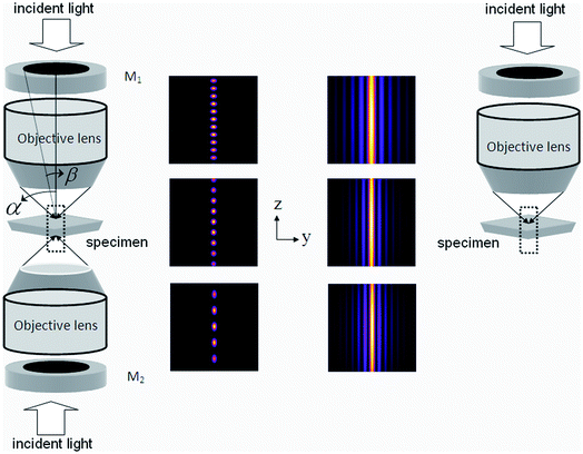
In this report, we propose an excitation technique for generating multi-spot excitation PSFs. The excitation multi-spot PSF is generated by the interference of two counter-propagating depth-of-focus PSFs as shown in Fig. 1. Each DoF-PSF is obtained by truncating the field in the central pupil plane of the objective lens.11 The incident light beam is appropriately expanded by a beam expander (not shown in Fig. 1) so as to cover fully the optical mask and back-aperture of the objective lens. The mask acts as a spatial filter in the Fourier domain enabling fine tuning of the axial profile of the illumination PSF and thus we achieve a near constant image intensity throughout the depth of field. We maintain a zero phase difference between the counter-propagating beams so as to generate interference pattern centered at the common geometrical focus. The resulting PSF has the capability for simultaneous multi-plane excitation for fast scanning in biological imaging. The detection is achieved by scanning the detector/pinhole assembly to selectively obtain fluorescent light from individual excitation spots. One way to perform z-discrimination on the fluorescent signal from multiple excitation spots is to split the signal into multiple confocal pinholes located at different z positions. Additionally, it must be noted that the splitting may cause a loss of fluorescent signal which needs to be taken care of for better signal-to-noise ratio (SNR).
 | ||
| Fig. 1 Left: schematic diagram of the optical setup for generating multi-spot PSF. The corresponding system PSF demonstrating multi-spot characteristic at α − β = 5° and varying aperture angle α = 45°, 60°, 72° is also shown. Right: single apodized lens based technique for generating Bessel-like extended depth-of-focus PSF. | ||
The schematic diagram illustrating the proposed imaging technique is shown in Fig. 1. A plane wave illuminates the optical mask (defined by amplitude transmission function) placed in the back focal plane of the objective lens (see Fig. 1). The Fourier transform of the transmitted amplitude appears in the Fourier plane of the lens. For low numerical aperture (NA), the field in the focal region of the objective lens is given by the Fourier transform of the apodized plane wave. But at large NA the vectorial nature of light becomes important because substantial portions of the wavefront are refracted through large angles. Calculations based on the vectorial nature of light for the determination of the x-, y-, and z-components of an electric field in a simple system such as an objective lens (NA = n sinα) are well established in ref. 15 and 16. The proposed system is a complex system which consists of two oppositely faced objective lens and a couple of optical masks. Vectorial calculations show that the resulting electric field components at the geometrical focus of such a complex system are [Ex, Ey, Ez] = [−iC(I′0 + I′2 cos 2ϕ), −iC I′2 sin 2ϕ, 2CI′1 cos ϕ] where the modified diffraction integrals over the aperture angle ‘α’ are given by,
In the proposed optical setup (Fig. 1), the excitation PSF (hexc) produced by phase-matched linearly-polarized light illumination (from both the sides) is: hexc(u,v,α − β) = |Ē(u,v,α − β) + Ē(−u,v,α − β)|2 = |Re I′0|2 + 4|Re I′1|2 cos2ϕ + |Re I′2|2 + 2cos(2ϕ)Re I′0 Re I′2, where (α − β) represents the outermost annulus through which light transmits. Since fluorescence emission is randomly polarized, the detection PSF at an aperture angle α is given by: hdet(u,v,α) = |I′0|2 + 2|I′1|2 + |I′2|2. The system PSFs for single- and two-photon excitations are, h1PEsys = hexc(u,v,α − β) × hdet(u,v,α), and h2PEsys = |hexc(u,v,α − β)|2 × hdet(u,v,α). It is worthwhile to note that the proposed optical system generates a 4PI-A-type PSF7 for plane wave illumination i.e., when the amplitude transmission function H[θ − β] = 1.
Computational studies were carried out to characterize the system PSF. The optical mask generates an apodized wavefront, and it is characterized by the transmission angle (α − β). A transmission angle of (α − β) = 5° is chosen for the proposed study. The β-values are 40°, 55° and 67° respectively for aperture angles 45°, 60° and 72°. The excitation wavelengths for single- and multi-photon excitation were chosen as 488 nm and 780 nm respectively. The sampling is 30 nm along both the axial and lateral axis. The integration over the diffraction integrals I0, I1 and I2 was carried out over the transmission angle (α − β). In the proposed technique, multiple axial locations are simultaneously excited by the multi-spot PSF. The detection scheme consists of scanning the detector/pinhole assembly in the Z-axis to successively collect light from different excitation spots. To facilitate Z-scanning, we have introduced and characterized multi-spot excitation with confocal detection rather than wide-field detection. It should be noted that the optical mask is not in the detection path and this is taken care of by the detection PSF hdet(u,v,α). The signal is collected from a single objective lens similar to a 4PI type A system. Additionally, alternate methods need to be employed to boost the SNR of the output fluorescence signal. The proposed technique does not improve the lateral resolution of the optical system.
We proceed by characterizing the excitation PSF. The excitation PSF is the result of the interference pattern produced by phase-matched counter-propagating depth-of-focus beams. The PSF is uniformly spread throughout the optical axis. The effect of aperture engineering for a single lens based system producing an extended DoF-PSF is shown in Fig. 1 (right). The situation dramatically changes with a setup of two opposing apodized lenses as shown in Fig. 1 (left). The resultant field splits into highly localized isolated excitation spots due to the interference effect. The aperture angle determines the number of excitation spots produced along the optical axis, as is evident from the system PSF (see Fig. 1, left).
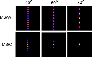
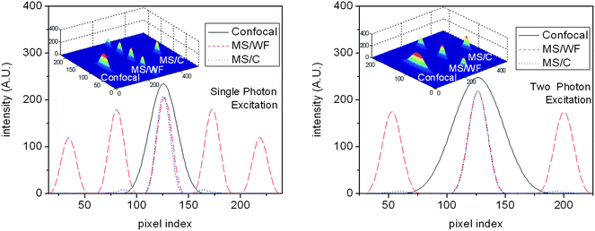
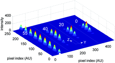
We employed a confocal detection scheme along with efficient Z-scanning. The corresponding system PSF (multi-spot excitation with confocal detection (MS/C)) is shown in Fig. 2. At a low aperture angle, the spot density increases because of large detection PSF. With increasing aperture angle, the confocal detection PSF shrinks, resulting in the controlled and selective detection of fluorescence light from individual spots. Confocal detection along with Z-scanning is required for selectively gathering photons from individual excitation spot. At aperture angles α = 60° and 72°, the fluorescence emission is essentially from 3 and 1 excitation spots, thereby giving a handle for quantizing photons from different planes of the specimen. This shows that the technique is better suited for applications based on large NA. On the other hand, multi-spot excitation with widefield detection (MS/WF) scheme does not allow selectivity and control. Confocal detection gives the user the ultimate control of nano-scale excitation spot (size ≈ 180 nm for α = 60°) and the number of spots can be varied by simply changing the aperture angle which scales detection PSF. Adaptability to multi-photon microscopy is carefully evaluated. Fig. 2 shows that multi-photon excitation has the added advantage of generating highly localized PSF (size ≈240 nm for α = 60°. A preliminary report related to multi-photon imaging is reported in ref. 17. Intensity plots were used to characterize the PSF for both single- and multi-photon microscopy. Line plots shown in Fig. 3 reveal that, the excitation spots in the proposed PSF is evenly spaced and are significantly well-localized as compared to the confocal PSF. Both MS/C and MS/WF imaging schemes are shown and compared with confocal PSF demonstrating 3-fold improvement in axial resolution. The PSF is assessed in terms of FWHM values. Additionally, the side-lobes are substantially suppressed for the two-photon PSF as compared to the single-photon case. Next we characterize the excitation PSF for a varying stop angle (β) which manipulates the excitation PSF. Fig. 4 shows the resulting excitation PSF for β = 55°, 40°, 20°, 0° respectively for an aperture angle α = 60°. The apodized wavefront gets modified to plane wavefront for β→0, thereby localizing the interference pattern centered at the common geometrical focus of the objective lens system. At β = 0°, the proposed PSF resembles 4PI-A type PSF.6
 | ||
| Fig. 2 The system PSF for both MS/WF and MS/C operational modes at α − β = 5° and aperture angle α = 45°, 60°, 72°. The selectivity property of the MS/C scheme is clearly evident especially at high numerical aperture (60°and 72°). | ||
 | ||
| Fig. 3 Intensity plots along with the 3D PSF for proposed multi-spot excitation for both MS/WF and MS/C scheme for an aperture angle α = 75° and α − β = 5°. Adaptability of the proposed technique for multi-photon imaging (excitation wavelength: 780nm) is clearly evident. Corresponding confocal PSF is also shown for comparison. | ||
 | ||
| Fig. 4 The PSF at varying stop angles, β = 55°, 40°, 20° and 0° for an aperture angle α = 60°. The intensity uniformity of the excitation spot is clearly manifested at 55°. At the other extreme (β = 0°), the system resembles the 4PI-A-type PSF. | ||
To conclude, a bioimaging technique is proposed to produce a tailor-made multi-spot system PSF for both single- and multi-photon microscopy. The proposed technique introduces the concept of simultaneous multi-plane excitation and its (spot density) control by confocal detection. The system PSF can be manoeuvred by scaling the detection PSF and by efficient Z-scanning. Easy integration of the proposed techniques with other bioimaging modalities makes it a versatile tool for achieving simultaneous multi-plane excitation in nanoscale imaging and simultaneous 3D study of molecular dynamics in the biological specimens. A multi-focal excitation technique may find potential applications in optical tweezers for trapping and manipulation of molecules. Additionally, fluorescence correlation spectroscopy can benefit from such an excitation technique. In particular, diffusion studies can be performed simultaneously on multiple sample layers and for determining molecular interactions of multiple species.
Acknowledgements
This work was partly done at Department of Instrumentation, Indian Institute of Science, Bangalore 560012, IndiaReferences
- T. Wilson and C. J. R. Sheppard, Theory and Practice of Scanning Optical Microscopy, Academic, London, 1984 Search PubMed.
- C. C. J. R. Sheppard and A. Choudhury, Opt. Acta, 1977, 24, 1051 Search PubMed.
- W. Denk, J. H. Strickler and W. W. Webb, Science, 1990, 248, 73 CrossRef CAS.
- A. Esposito, F. Federici, C. Usai, F. Cannone, G. Chirico, M. Collini and A. Diaspro, Microsc. Res. Tech., 2004, 63, 12 CrossRef CAS.
- P. P. Mondal, G. Vicidomini and A. Diaspro, Appl. Phys. Lett., 2008, 92, 103902 CrossRef.
- S. W. Hell, Science, 2007, 316, 1153 CrossRef CAS.
- S. W. Hell and Stelzer, Opt. Commun., 1992, 93, 277 CrossRef.
- G. Toraldo di Francia, Nuovo Cimento, 1952, 9(Suppl. 9), 426 Search PubMed.
- P. P. Mondal and A. Diaspro, Opt. Commun., 2008, 281, 1855 CrossRef CAS.
- M. A. A. Neil, R. Juskaitis, T. Wilson and Z. J. Laczik, Opt. Lett., 2000, 25, 245 Search PubMed.
- E. E. J. Botcherby, R. Juskaitis and T. Wilson, Opt. Commun., 2006, 268, 253 CrossRef CAS.
- G. H. Patterson and D. W. Piston, Biophys. J., 2000, 78, 2159 CrossRef CAS.
- P. P. Mondal and A. Diaspro, Phys. Rev. E: Stat., Nonlinear, Soft Matter Phys., 2007, 75, 061904 CrossRef.
- P. P. Mondal, R. J. Gilbert and P. T. C. So, Appl. Phys. Lett., 2008, 93, 093901 CrossRef.
- B. Richards and E. Wolf, Proc. R. Soc. London, Ser. A, 1959, 253, 358 CrossRef.
- A. Boivin and E. Wolf, Phys. Rev., 1965, 138, B1561 CrossRef.
- P. P. Mondal, Rev. Sci. Instrum., 2009, 80, 096104 CrossRef.
| This journal is © The Royal Society of Chemistry 2010 |

