 Open Access Article
Study on the growth kinetics of methane hydrate in pure water system containing ZIF-8
Xiaofang Lv *ab,
Boyu Bai
 a,
Shangbin Liangb,
Wenguang Zengb,
Yang Liu
 *a,
Qianli Maa,
Haifeng Zhangc,
Chuanshuo Wanga and
Shidong Zhou
 a
a
aJiangsu Key Laboratory of Oil and Gas Storage & Transportation Technology, Changzhou University, Changzhou 213016, China. E-mail: lvxiaofang5@cczu.edu.cn; liu.y@cczu.edu.cn; Tel: +86 0519-8633-0860
bChina Petroleum & Chemical Corporation Northwest Oilfield Branch, Petroleum Engineering Technology Research Institute, Urumqi 830011, China
cResearch Institute of Tsinghua, Pearl River Delta, Guangzhou 510700, China
First published on 1st August 2022
Abstract
The hydrate formation rate is the key to the implementation of solid gas storage and transportation technology by the hydrate method. As a MOF material with strong hydrothermal stability, ZIF-8 has been proved to play a significant role in promoting the nucleation and growth of hydrate. However, the growth kinetics promotion mechanism and growth law of methane hydrate in the ZIF-8 promoter system have not been clarified at present. Therefore, the growth kinetics experiment of methane hydrate in the ZIF-8 promoter system was carried out in a high-pressure visualization reactor to systematically study the effects of the ZIF-8 concentration, undercooling degree, and pressure on the growth law of methane hydrate. The experimental results showed that: (1) the concentration of ZIF-8 had a significant shortening effect on the induction period of methane hydrate. With the increase in the ZIF-8 concentration, the induction time of methane hydrate was shortened from 5.85 h to 0.85 h. The methane gas consumption showed a gradually increasing trend at first, and then with the reaction going on, a dense hydrate film was formed at the gas–liquid interface, which increased the mass transfer resistance, resulting in the increase in the methane gas consumption gradually becoming stable. There were four stages in the growth process of hydrate, namely rapid formation, slow formation, secondary formation, and end formation and the optimal dosage of ZIF-8 promoter exists, and the optimal critical specific content was 0.02 mg mL−1. (2) With the increase of undercooling, the induction time of methane hydrate decreased significantly, and the increase in the methane consumption also showed an increasing trend at first and then decreased. (3) With the increase of the system pressure to 7 MPa, the induction time of methane hydrate decreased from 1.02 h at 6 MPa to 0.2 h at 7 MPa, and the decrease rate was 80.8%, which was mainly due to the presence of “OPEN GATE” in the ZIF-8 accelerator. With the increase of the system pressure, the pore opening of the ZIF-8 material increased, the adsorption of methane increased, and the nucleation and growth of methane hydrate were promoted.
1. Introduction
With the gradual increase of carbon emissions from human activities and the increasing global warming, it is urgent to reduce the atmospheric greenhouse gas concentration in two aspects, reducing greenhouse gas emissions and sealing greenhouse gas.1 As an envelope compound,2 methane hydrate has a high energy density and strong gas storage capacity. The gas storage density under standard conditions can reach 180 v/v,3 which is undoubtedly an optional way to reduce greenhouse gas emissions and achieve carbon neutralization. At the same time, the hydrate also has a self-protection effect under non-thermodynamic equilibrium conditions, that is, when the temperature is reduced to below the freezing point, a layer of ice will form around the hydrate particles, which hinders the decomposition of the hydrate.4,5 At this time, the preservation pressure of the hydrate can be reduced to atmospheric pressure.6 Therefore, the storage and transportation of natural gas with methane as the main component is safer than liquefied natural gas or pipeline transportation by using the storage characteristics of methane in hydrates. However, the difficulty in the formation of natural gas hydrate is one of the reasons why it is difficult to carry out commercial applications. Exploration of hydrate kinetic promoters is a major direction to achieve the rapid and efficient formation of natural gas hydrates.5In recent years, MOFs have attracted widespread attention due to their microporous, high surface area, diversity, and designable topology.7 ZIF-8 is the most studied material for the thermochemical stability of MOF materials, which have excellent thermal stability (550 °C) and stable chemical properties (energy storage stability in organic solvents and other solutions).8,9 ZIF-8 has a sodalite structure with a cubic lattice and pore size of 1.16 nm.10–12 Different from other zeolites with a rigid framework, the crystal structure of ZIF-8 has good elasticity. Gas molecules (N2, CH4, C2H6, and C3H8) with a kinetic diameter larger than the ZIF-8 pore size can diffuse freely through ZIF-8.13–15 In addition, 2-methylimidazole with high hydrophobicity exists in the ZIF-8 material, which promotes the growth of hydrate and improves the conversion rate of methane hydrate.16 Other studies have shown that hydrophobic surfaces do not negatively affect the ordering of water molecules necessary for hydrate nucleation,17,18 which further supports the positive role of hydrophobicity in the hydrate growth. Zhang et al.19 revealed the adsorption mechanism of water in the ZIF-8 cavity. They found that H2O molecules filled ZIF-8 holes one by one and formed stable clusters through hydrogen bonds. Ma et al.20 investigated the dry and wet storage properties of ZIF-8 for methane through methane adsorption experiments. CH4 adsorption capacity of dry ZIF-8 was 163 v/v at 274.15 K and 10 MPa. The methane adsorption capacity of wet ZIF-8 without pre-adsorption water increased with the increase in pressure, and hydrate was formed on the surface of wet ZIF-8.
Mu et al.21 studied the adsorption and hydrate formation behavior of methane in five kinds of wet ZIF-8 molecular sieves with different water contents (0.0%, 16.3%, 27.7%, 30.6% and 35.1%, mass fraction), and determined the gas storage capacity of the ZIF-8 skeleton and ZIF-8 particle bed. The experimental results showed that hydrate can be formed in the wet pore of the ZIF-8 molecular sieve, which greatly improved the methane storage capacity of the ZIF-8 skeleton and ZIF-8 particle bed. At 269.15 K and 2.85 MPa, the net gas storage of the wet ZIF-8 skeleton with a moisture content of 35.13% was 56% higher than that of the dry ZIF-8 skeleton, which was consistent with the experimental results of Liu et al.22 The ideal volume storage capacity of the wet ZIF-8 skeleton can reach more than 190 v/v at about 3.0 MPa, 7% higher than the US Department of Energy target for methane storage (180 v/v). The optimum moisture content of the wet ZIF-8 granular bed was 30.6%, and the actual volume storage capacity can reach 150 v/v at 6.5 MPa.
Denning et al.23 studied the promotion effect of a ZIF-8 microporous zeolite imidazolyl alcohol skeleton as a promoter for methane hydrate formation. The results showed that ZIF-8 increases the hydrate conversion rate of the water–methane system from 4.5% without water to 85.6%, with the highest mass ratio of water to ZIF-8 of 0.38, and the gas storage capacity increased by 14.4 times. At the same time, isothermal experiments showed that ZIF-8 reduced the nucleation induction time of methane hydrate by 51.6%. In addition, during the experiment, ZIF-8 maintained the integrity of the structure and showed consistent reusability, indicating that the material could be recycled as a promoter and had a long service life.
Different researchers have studied ZIF-8 as a promoter of methane hydrate formation and obtained important experimental rules, but the research on its promotion mechanism still needs further exploration. Therefore, this experiment mainly carried out the methane hydrate formation experiment under the ZIF-8 system through a large-capacity and high-pressure visual reactor to explore the influence of ZIF-8 on the formation kinetics of methane hydrate, providing support for the exploration of the promotion mechanism of ZIF-8 and finding the critical optimal content of ZIF-8 in the liquid phase.
2 Experimental apparatus and procedure
2.1 High-pressure hydrate reactor and related equipment
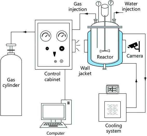
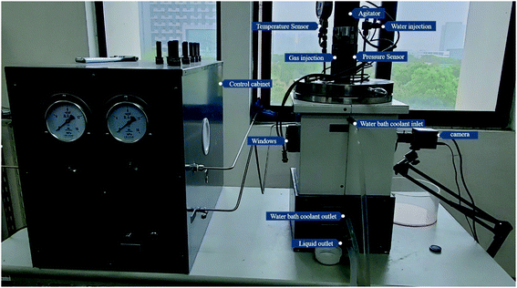
The high-pressure reactor equipment includes a hydrate reaction system, a gas supply system, a temperature control system, and a data acquisition system. The core of the system is the reactor body made of 316 L stainless steel with a net volume of 4 L, which is equipped with a sapphire window, and the volume of the reactor is controlled by supporting iron blocks (316 L, 0.8 L). The temperature control system includes the reactor water bath jacket and the DC-3010 low temperature constant temperature water bath tank manufactured by Suzhou Kesiluo Industrial Equipment Co., Ltd. The temperature control range is −20 °C to 80 °C with an accuracy of 0.1 K. The data acquisition system includes a temperature sensor, a pressure sensor, and a data acquisition card. The temperature detection adopts a T-type thermocouple (precision 0.1 K), and the pressure monitoring adopts a PTX5072 type pressure sensor (precision 0.01 MPa) of General Electric Sensing and Inspection (Changzhou) Co., Ltd The information acquisition card is Altai acquisition card-DAM3058R/Altai acquisition card-DAM3134. The schematic of the experimental system is shown in Fig. 1.2.2 Experimental materials
Methane (99.99%) was supplied by Changzhou Jinghua Industrial Gas Co., Ltd Deionized water was self-made in the laboratory. ZIF-8 was obtained from Nanjing Xianfeng Nanotech Materials Technology Co., Ltd, which was prepared by the hydrothermal method. Detailed information is shown in Table 1.| Component | Suppliers | CAS reg. no. | Mass fraction | Structural information | Analysis method |
|---|---|---|---|---|---|
| a Gas chromatograph. | |||||
| Methane | Changzhou Jinghua Industrial Gas Co., Ltd | 74-82-8 | 0.9999 | GCa | |
| Deionized water | Self-made | 7732-18-5 | |||
| ZIF-8 | Nanjing Xianfeng Nanotech Materials Technology Co., Ltd | 59061-53-9 | The average particle size = 1 μm. BET surface area = 1345 m2 g−1. The pore size = 1.16 nm | ||
2.3 Experiment procedures
(1) The experimental conditions for each group are shown in Table 1. To clean the reactor with deionized water and carbon dioxide before the start of each experiment, an appropriate amount of deionized water is added while cooling through a water bath in the end.(2) When the temperature of deionized water in the reactor reaches the predetermined temperature, an appropriate amount of ZIF-8 is added to open the exhaust valve and allow the methane gas at the same time. After discharging the air in the reactor, the exhaust valve is closed (Fig. 2).
(3) Methane is allowed to pass through continuously and about 3 min is required to reach the predetermined pressure to close the inlet, followed by magnetic stirring with the speed set to 200 rpm. (when the speed is set higher, the nucleation and formation rate of the hydrate is too fast, and in order to better control the initial conditions of the experiment, 200 rpm is selected for the experiment);
(4) The temperature and pressure changes over time are recorded by the reactor temperature sensor and pressure sensor, and the experimental process in the reactor is recorded by the camera at the sapphire window;
(5) When the pressure in the reactor remains unchanged for 1 h and the temperature does not show a significant upward trend, it is considered that the hydrate reaction is basically completed. The experiment is completed and repeated three times in each group to verify the reliability of the data;
(6) The ZIF-8 used in each experiment was dried in a 120 °C air dryer for 12 h, and the dried ZIF-8 had strong hydrophobicity, which could not be uniformly distributed in the liquid phase through ultrasonic oscillation. Due to the presence of van der Waals forces, ZIF-8 was concentrated on the surface of the liquid phase, so the liquid phase was directly added to the kettle, and magnetic stirring was carried out to make it more dispersed in the liquid phase (Table 2).
| Case | ZIF-8 content, mg mL−1 | Water bath temperature, °C | Initial pressure, MPa | Gas–liquid ratio | Magnetic stirring speed, rpm |
|---|---|---|---|---|---|
| 1 | 0 | 2 | 6 | 5![[thin space (1/6-em)]](https://www.rsc.org/images/entities/char_2009.gif) : :![[thin space (1/6-em)]](https://www.rsc.org/images/entities/char_2009.gif) 1 1 |
200 |
| 2 | 0.01 | 2 | 6 | 5![[thin space (1/6-em)]](https://www.rsc.org/images/entities/char_2009.gif) : :![[thin space (1/6-em)]](https://www.rsc.org/images/entities/char_2009.gif) 1 1 |
200 |
| 3 | 0.02 | 2 | 6 | 5![[thin space (1/6-em)]](https://www.rsc.org/images/entities/char_2009.gif) : :![[thin space (1/6-em)]](https://www.rsc.org/images/entities/char_2009.gif) 1 1 |
200 |
| 4 | 0.03 | 2 | 6 | 5![[thin space (1/6-em)]](https://www.rsc.org/images/entities/char_2009.gif) : :![[thin space (1/6-em)]](https://www.rsc.org/images/entities/char_2009.gif) 1 1 |
200 |
| 5 | 0.05 | 2 | 6 | 5![[thin space (1/6-em)]](https://www.rsc.org/images/entities/char_2009.gif) : :![[thin space (1/6-em)]](https://www.rsc.org/images/entities/char_2009.gif) 1 1 |
200 |
| 6 | 0.02 | 4 | 6 | 5![[thin space (1/6-em)]](https://www.rsc.org/images/entities/char_2009.gif) : :![[thin space (1/6-em)]](https://www.rsc.org/images/entities/char_2009.gif) 1 1 |
200 |
| 7 | 0.02 | 3 | 6 | 5![[thin space (1/6-em)]](https://www.rsc.org/images/entities/char_2009.gif) : :![[thin space (1/6-em)]](https://www.rsc.org/images/entities/char_2009.gif) 1 1 |
200 |
| 8 | 0.02 | 2 | 6 | 5![[thin space (1/6-em)]](https://www.rsc.org/images/entities/char_2009.gif) : :![[thin space (1/6-em)]](https://www.rsc.org/images/entities/char_2009.gif) 1 1 |
200 |
| 9 | 0.02 | 1 | 6 | 5![[thin space (1/6-em)]](https://www.rsc.org/images/entities/char_2009.gif) : :![[thin space (1/6-em)]](https://www.rsc.org/images/entities/char_2009.gif) 1 1 |
200 |
| 10 | 0.02 | 0 | 6 | 5![[thin space (1/6-em)]](https://www.rsc.org/images/entities/char_2009.gif) : :![[thin space (1/6-em)]](https://www.rsc.org/images/entities/char_2009.gif) 1 1 |
200 |
| 11 | 0.02 | 6 | 8 | 5![[thin space (1/6-em)]](https://www.rsc.org/images/entities/char_2009.gif) : :![[thin space (1/6-em)]](https://www.rsc.org/images/entities/char_2009.gif) 1 1 |
200 |
| 12 | 0.02 | 4.5 | 7 | 5![[thin space (1/6-em)]](https://www.rsc.org/images/entities/char_2009.gif) : :![[thin space (1/6-em)]](https://www.rsc.org/images/entities/char_2009.gif) 1 1 |
200 |
| 13 | 0.02 | 3 | 6 | 5![[thin space (1/6-em)]](https://www.rsc.org/images/entities/char_2009.gif) : :![[thin space (1/6-em)]](https://www.rsc.org/images/entities/char_2009.gif) 1 1 |
200 |
| 14 | 0.02 | 1 | 5 | 5![[thin space (1/6-em)]](https://www.rsc.org/images/entities/char_2009.gif) : :![[thin space (1/6-em)]](https://www.rsc.org/images/entities/char_2009.gif) 1 1 |
200 |
| 15 | 0.02 | −1 | 4 | 5![[thin space (1/6-em)]](https://www.rsc.org/images/entities/char_2009.gif) : :![[thin space (1/6-em)]](https://www.rsc.org/images/entities/char_2009.gif) 1 1 |
200 |
3 Results and analysis
3.1 Influence of the content of ZIF-8 set on formation kinetic
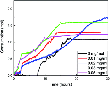
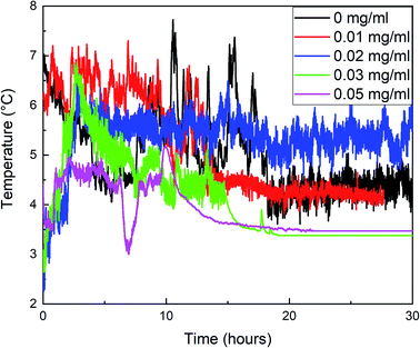
In this section, the effects of ZIF-8 content (0.01 mg mL−1, 0.02 mg mL−1, 0.03 mg mL−1, and 0.05 mg mL−1) on the growth kinetics of methane hydrate are investigated under the conditions of cases 1 to 5. The specific results are shown in Fig. 3–6. It can be seen from Table 3 that compared with the control group without ZIF-8, even if the content of ZIF-8 is only 0.01 mg mL−1, the induction time (macroscopic induction time) of methane hydrate in the reactor is also shortened from 5.85 to 1.7 h, with a decrease of 70.1%. The addition of ZIF-8 in the liquid phase provides the nucleation site of methane hydrate, which significantly promotes the nucleation process of the hydrate. With the increase in the ZIF-8 content, the induction time continues to decline, 0.85 h at 0.05 mg mL−1.| Case | ZIF-8 content, mg mL−1 | The methane hydrate nucleation induction time, h |
|---|---|---|
| 1 | 0 | 5.85 |
| 2 | 0.01 | 1.70 |
| 3 | 0.02 | 1.33 |
| 4 | 0.03 | 1.00 |
| 5 | 0.05 | 0.85 |
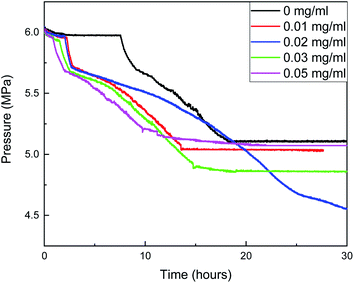
The changes of gas consumption, pressure, and temperature with time during the formation of methane hydrate in the reactor are shown in Fig. 3, 4, and 5. Fig. 3 illustrates that the formation process of methane hydrate in the ZIF-8 system is divided into four stages: rapid formation, slow formation, secondary formation, and end formation. The rapid formation stage mainly occurs at the gas–liquid interface, but the hydrate will form a hydrate film, covering the gas–liquid interface, hindering the mass transfer process of methane and water. Only relying on the capillary of the hydrate film for the diffusion of methane and water can the hydrate formation slow down. With the continuous slow formation of hydrate in the hydrate film, the concentration of methane in the liquid phase decreases continuously. The heat release during hydrate formation decreases due to the slow formation rate, and the temperature in the system also gradually decreases. Meanwhile, the driving force increases, resulting in the rupture of the hydrate film. The contact area between methane and liquid phase increases suddenly, and the hydrate begins to generate again. Then, with the decrease of the driving force, the hydrate formation gradually ends.
As shown in Fig. 4, the gas consumption in the process of hydrate formation increases with the increase in the ZIF-8 content in the range of 0–0.02 mg mL−1, but decreases when the content is greater than 0.02 mg mL−1. Therefore, it was considered that the optimal critical content of ZIF-8 was 0.02 mg mL−1 under the experimental conditions. When the content of ZIF-8 is 0.02 mg mL−1, gas consumption is the largest, and gas consumption fluctuates around 0.075 mol within 0–2.01 h after the beginning of the reaction, which is the amount of dissolved methane in the liquid phase. Hydrate was rapidly formed within 2.01–2.64 h, and the gas consumption increased from 0.075 mol to 0.3 mol. Then, the gas consumption rate decreased first and then increased. At the end of the reaction, gas consumption was 1.99 mol, which was 1.875 times that of the blank group.
The reaction does not stop until about 40 h when the ZIF-8 content was 0.02 mg, and the time from the reaction to equilibrium was more than twice that of the four groups. It was considered that the number of methane molecules adsorbed by ZIF-8 was moderate, the amount of hydrate formation was moderate during the rapid formation of hydrate, the structure of the hydrate membrane was loose, and the pores were rich. The effective diffusion coefficients of water and methane in the hydrate membrane were large, and the boundary between the slow formation and the secondary formation of hydrate was not obvious, so the hydrate could be further generated at a faster rate. When the content of ZIF-8 was lower than 0.02 mg mL−1, the effect of hydrate film on mass transfer was smaller, and the growth rate in the secondary formation stage of hydrate was faster than that when the content of ZIF-8 was 0.02 mg mL−1. However, the adsorption amount of methane in the liquid phase was also reduced due to the low content of ZIF-8. Although it did not hinder the nucleation of hydrate, the total production of hydrate was reduced.
When the content of ZIF-8 was greater than 0.03 mg mL−1, although the formation rate of hydrate in the rapid formation period was not significantly different from that when the content of ZIF-8 was low, the adsorption amount of methane increased when the content of ZIF-8 was high, resulting in a large number of methane hydrates at the gas–liquid interface. In combination with Fig. 5, when the content of ZIF-8 was 0.03 mg mL−1 and 0.05 mg mL−1, the temperature was flat at the end of the reaction without evident fluctuation, and the actual formation of hydrate in the system after the end of the reaction when the content of ZIF-8 was 0.03 mg mL−1, as shown in Fig. 6. It is judged that the formation of a dense hydrate shell in the reactor can restrict the rotation of blades, which hinders the mass transfer process of water and methane and hinders the further formation of hydrate.
3.2 Influence of the degree of undercooling set on formation kinetic
In this section, under the conditions of cases 6 to 10, the effect of undercooling on the growth kinetics of methane hydrate is investigated. The water bath temperatures are set to 0 °C, 1 °C, 2 °C, 3 °C, and 4 °C, and the corresponding degree of undercooling are about 6 °C, 5 °C, 4 °C, 3 °C, and 2 °C. Table 4 shows the data on water bath temperature and hydrate induction time. The induction time is the average value of three experiments. It can be noticed that with the decrease in the water bath temperature, the induction time decreases clearly. The induction time is 1.33 h at 4 °C and 0.33 h at 5 °C, which decreases by 75.2%.| Case | Water bath temperature, °C | The methane hydrate nucleation induction time, h |
|---|---|---|
| 6 | 4 | 1.16 |
| 7 | 3 | 1.04 |
| 8 | 2 | 1.33 |
| 9 | 1 | 0.35 |
| 10 | 0 | 0.45 |
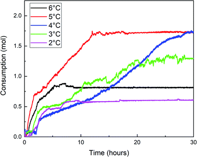
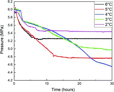
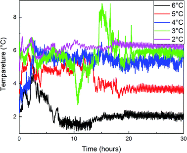
Fig. 7, 8, and 9 are the gas consumption, pressure, and temperature changes of methane hydrate formation reaction under different water bath temperatures.
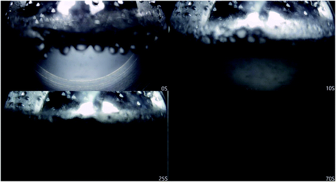
Fig. 7 shows that methane consumption increases first and then decreases with the increase of water bath temperature, and the maximum gas consumption is at 4 °C. When the undercooling degree is greater than 4 °C, the driving force of hydrate formation is large. The hydrate formation rate is faster than when the water bath temperature is high, and a dense hydrate shell will be formed on the gas–liquid interface in the reactor, which hinders the mass transfer of methane. This makes the methane consumption decrease during the secondary formation of hydrate, and the final hydrate is dense and hard (Fig. 10A), and the lower the temperature is, the more obvious it is. With the increase of water bath temperature, the driving force of hydrate formation decreased, the nano-convection rate of methane and water decreased, the adsorption and hydrate formation rate decreased, the gas consumption of methane also decreased, and the generated hydrate was relatively loose and soft (Fig. 10B). From the window observation, it can be seen that when the undercooling degree is 2 °C, the hydrate is rapidly formed after nucleation, and the generated hydrate slurry is blocked by light at the window after about 70 s, which cannot be further observed (Fig. 11). When the undercooling was 6 °C, the process lasted only 25 s (Fig. 12).
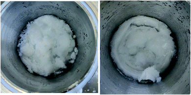 | ||
| Fig. 10 (A) photos of hydrate formation (degree of under cooling = 4 °C), (B) photos of hydrate formation (degree of under cooling = 2 °C). | ||
The temperature variation trend of the hydrate formation process under different water bath temperatures in Fig. 9 showed that the temperature rises most when the undercooling degrees are 5 °C, 4 °C, and 3 °C, and the temperature rises with multi-terminal fluctuations under different water bath temperatures and maintains for a long time at a higher temperature. Combined with Fig. 7 and 8, it can be seen that the hydrate formation process is divided into multiple sections, and the gas consumption and pressure drop were large under these three conditions, resulting in a large number of hydrate formation.
3.3 Influence of pressure set on formation kinetic
The effects of pressure (4 MPa, 5 MPa, 6 MPa, 7 MPa, 8 MPa) on the growth kinetics of methane hydrate are studied under the conditions of cases 11 to 15. Table 5 shows the induction time of hydrate formation under different pressures. It can be seen that the induction time is 0.23 h when the pressure rises to 7 MPa, and 1.04 h when the pressure is 6 MPa, which is decreased by 77.9%. This is related to the “OPEN GATE” phenomenon of ZIF-8. With the increase in pressure, the pore opening of the ZIF-8 material increases, the adsorption and diffusion rate of methane in the pore is fast, the contact area between the gas and liquid phase is improved, and the nucleation and growth of methane hydrate are promoted.| Case | Initial pressure, MPa | The methane hydrate nucleation induction time, h |
|---|---|---|
| 11 | 8 | 0.20 |
| 12 | 7 | 0.23 |
| 13 | 6 | 1.04 |
| 14 | 5 | 1.01 |
| 15 | 4 | 0.97 |
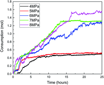
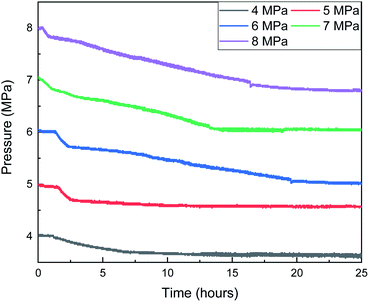
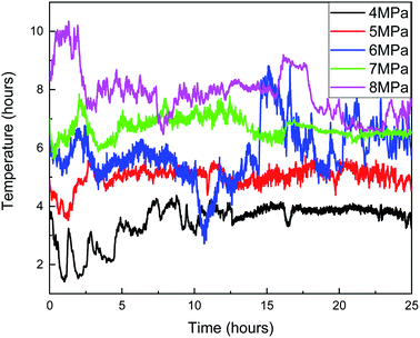
Fig. 13, 14, and 15 are the gas consumption, pressure, and temperature changes of the methane hydrate formation reaction under different pressures, respectively.
Fig. 13 shows that the gas consumption increases with the increase in the gas pressure. When the gas pressure is 8 MPa, the gas consumption is 1.56 mol, and when the gas pressure is 4 MPa, the gas consumption is only 0.46 mol. In addition, combined with the curves of gas consumption and pressure with time in Fig. 13 and 14, with the increase in the gas pressure, the variation trend of gas consumption is different, indicating that the formation process of the hydrate is different. When the gas pressure is above 6 MPa, after the hydrate formation induction period, there are a clear hydrate rapid formation period and hydrate secondary formation process, and then the hydrate slowly generates and finally terminates. When the gas pressure is 5 MPa, the hydrate formation rate decreases obviously after the rapid hydrate formation period, indicating that the hydrate film hinders the mass transfer process of water and methane, but there is no obvious secondary hydrate formation process, indicating that when the initial gas pressure is 5 MPa, the hydrate formation driving force is small and cannot destroy the hydrate film. When the gas pressure is 4 MPa, after the induction period of hydrate formation, there is no clear boundary between the rapid hydrate formation period and the secondary hydrate formation process. The hydrate formation rate is similar to that of the secondary hydrate formation process under a high gas pressure, indicating that under this experimental condition, not only is the driving force of hydrate formation small but also the hydrate film that can effectively hinder the mass transfer process cannot be formed.
In Fig. 13, when the pressure was 8 MPa, after the induction period of hydrate formation, the hydrate formation rate reached the maximum before 2.5 h. Combined with Fig. 15, with the formation of hydrate, the temperature rise of the reactor was more indigenous than that at other pressures. When the maximum temperature reached 10.3 °C, the subcooling degree in the system was only 0.5 °C, and the heat could not be taken away by the cooling medium in time. Therefore, the local temperature in the system was higher than the maximum temperature of hydrate formation under this pressure, leading to the decomposition of hydrate and a decrease in gas consumption. The same is true at 14.5 h when the pressure is 6 MPa.
4 Conclusions
The effects of ZIF-8 addition, pressure, and undercooling in the reaction system on the formation process of methane hydrate were studied under the condition that ZIF-8 was used as the promoter of methane hydrate in a pure water system. The following important conclusions were obtained:(1) With the increase in the ZIF-8 content from 0 to 0.05 mg mL−1, the induction period of hydrate was shortened from 5.85 h to 0.85 h, and the methane consumption rate was accelerated. Subsequently, the hydrate formation process can be clearly divided into four stages: rapid formation, slow formation, secondary formation, and the end of the formation. When the content of ZIF-8 was lower than 0.02 mg mL−1, the hydrate film was loose, and it was difficult to distinguish the growth slowdown stage from the secondary formation stage. However, due to the low adsorption amount of methane in the liquid phase, it was not conducive to the growth of hydrate. When the content of ZIF-8 was higher than 0.03 mg mL−1, the hydrate formation was too fast, forming a dense hydrate film, which hindered the further formation of hydrate. Therefore, the critical optimal content of ZIF-8 was 0.02 mg mL−1 under the experimental conditions.
(2) With the increase in the undercooling degree, the induction time of hydrate decreased from the highest 1.33 h to the lowest 0.33 h. The hydrate formation rate increased and the gas consumption increased first and then decreased. The hydrate morphology gradually changed from loose and soft to dense and hard, and the dense hydrate shell played a crucial role in hindering the growth of hydrate. Therefore, the nucleation of hydrate can be promoted under the condition of large undercooling, and then the undercooling can be appropriately reduced to promote the further formation of hydrate and improve the conversion rate.
(3) The results of the experimental pressure group showed that the induction period of the hydrate decreased significantly with the increase in pressure. The induction period of the hydrate was 0.2 h at 7 MPa in the system and 1.02 h at 6 MPa, which was shortened by 80.8%. It was considered that the induction period was related to the OPENGATE phenomenon of ZIF-8. Under a high pressure, the pore opening of the ZIF-8 material increased, and the adsorption of methane increased, which promoted the contact area between the gas phase and the liquid phase and promoted the nucleation and growth of methane hydrate. Therefore, the hydrate induction period can be effectively shortened when the test pressure is above 7 MPa. However, when the pressure is too high, the gas–liquid interface will generate a dense hydrate film, and when the pressure is too low, the driving force of hydrate formation is insufficient, which affects the further formation of hydrate after the induction period.
Conflicts of interest
There are no conflicts to declare.Acknowledgements
This work was supported by the National Natural Science Foundation of China (Grant No. 51804046 & 52004039 & 51974037), China Postdoctoral Science Foundation (Grant No. 2021M693908), and the major project of universities affiliated to Jiangsu Province basic science (natural science) research (Grant No. 21KJA440001), Jiangsu Qinglan Project.References
- F. Wang, J. D. Harindintwali and Z. Yuan, et al., Technologies and perspectives for achieving carbon neutrality, The Innovation, 2021, 2(4), 100180 CrossRef PubMed.
- G. J. Chen, Gas hydrate science and technology, Chemical Industry Press, Bei Jing, 2019 Search PubMed.
- X. M. Lang, S. S. Fan and Y. H. Wang, Intensification of methane and hydrogen storage in clathrate hydrate and future prospect, J. Nat. Gas Chem., 2010, 19, 203–209 CrossRef CAS.
- D. S. Bai, D. W. Zhang and X. R. Zhang, et al., Origin of Self-preservation Effect for Hydrate Decomposition: Coupling of Mass and Heat Transfer Resistances, Sci. Rep., 2015, 5, 14599, DOI:10.1038/srep14599.
- Me Shurraya Denning, A. A. A. Majid and J. M. Lucero, et al., Methane Hydrate Growth Promoted by Microporous Zeolitic Imidazolate Frameworks ZIF-8 and ZIF-67 for Enhanced Methane Storage, Chem. Eng., 2021, 9, 9001–9010 Search PubMed.
- H. P. Veluswamy, A. Kumar, Y. Seo, J. D. Lee and P. A. Linga, Review of Solidified Natural Gas (SNG) Technology for Gas Storage via Clathrate Hydrates, Appl. Energy, 2018, 216, 262–285 CrossRef CAS.
- C. Z. Jia, H. Li and B. Liu, et al., Sorption Performance and Reproducibility of ZIF-8 Slurry for CO2/CH4 Separation with the Presence of Water in Solvent, Chem Eng. Res, 2018, 57, 12494–12501 CrossRef CAS.
- K. S. Park, Z. Ni and A. P. Côté, et al., Exceptional chemical and thermal stability of zeolitic imidazolate frameworks, Proc. Natl. Acad. Sci. U. S. A., 2006, 103(27), 10186–10191 CrossRef CAS PubMed.
- P. Kusgens, M. Rose and I. Senkovska, et al., Characterization of metal–organic frameworks by water adsorption, Microporous Mesoporous Mater., 2009, 120(3), 325–330 CrossRef.
- H. Liu, P. Guo and T. Regueira, et al., Irreversible Change of the Pore Structure of ZIF-8 in Carbon Dioxide Capture with Water Coexistence, J. Phys. Chem. C, 2016, 120, 13287–13294 CrossRef CAS.
- A. A. García Blanco, A. F. Vallone and S. A. Korili, A comparative study of several microporous materials to store methane by adsorption, Microporous Mesoporous Mater., 2016, 224, 323–331 CrossRef.
- Q. Shi, Z. Chen and Z. Song, et al., Synthesis of ZIF-8 and ZIF-67 by Steam-Assisted Conversion and an Investigation of Their Tribological Behaviors, Angew. Chem., Int. Ed., 2011, 50(3), 672–675 CrossRef CAS PubMed.
- H. Bux, F. Liang and Y. Li, et al., Zeolitic imidazolate framework membrane with molecular sieving properties by microwave-assisted solvothermal synthesis, J. Am. Chem. Soc., 2009, 131, 16000–16001 CrossRef CAS PubMed.
- H. Bux, C. Chmelik and J. M. van Baten, et al., Novel MOF-membrane for molecular sieving predicted by IR-diffusion studies and molecular modeling, Adv. Mater., 2010, 22, 4741–4743 CrossRef CAS PubMed.
- H. Bux, C. Chmelik and R. Krishna, et al., Ethene/ethane separation by the MOF membrane ZIF-8: Molecular correlation of permeation, adsorption, diffusion, J. Membr. Sci., 2011, 369, 284–289 CrossRef CAS.
- M. E. Casco, F. Rey and J. L. Jordá, et al., Paving the Way for Methane Hydrate Formation on Metal–Organic Frameworks (MOFs), Chem. Sci., 2016, 7(6), 3658–3666 RSC.
- C. A. Koh, R. P. Wisbey and X. Wu, et al., Water Ordering around Methane during Hydrate Formation, J. Chem. Phys., 2000, 113(15), 6390–6397 CrossRef CAS.
- D. Bai, G. Chen and X. Zhang, et al., How Properties of Solid Surfaces Modulate the Nucleation of Gas Hydrate, Sci. Rep., 2015, 5(1), 1–12 CAS.
- H. Zhang and R. Q. Snurr, Computational study of water adsorption in the hydrophobic metal–organic framework ZIF-8: adsorption mechanism and acceleration of the simulations, J. Phys. Chem. C, 2017, 121, 24000–24010 CrossRef CAS.
- R. Y. Ma, H. Y. Wang and L. Zhao, et al., Preparation of adsorption material ZIF-8 and its methane storage performance, Petrochem. Technol., 2015, 44(06), 719–723 CAS.
- L. Mu, B. Liu and H. Liu, et al., A novel method to improve the gas storage capacity of ZIF-8, J. Mater. Chem., 2012, 22, 12246–12252 RSC.
- L. Jia, Y. Zhou and Y. Sun, et al., Methane storage in wet carbon of tailored pore sizes, Carbon, 2011, 49(12), 3731–3736 CrossRef.
- Me Shurraya Denning, A. A. A. Majid and J. M. Lucero, et al., Methane Hydrate Growth Promoted by Microporous Zeolitic Imidazolate Frameworks ZIF-8 and ZIF-67 for Enhanced Methane Storage, Chem. Eng., 2021, 9, 9001–9010 Search PubMed.
| This journal is © The Royal Society of Chemistry 2022 |

