 Open Access Article
Creative Commons Attribution 3.0 Unported Licence
MoS2 quantum dot-modified MXene nanoflowers for efficient electrocatalytic hydrogen evolution reaction†
Savan K.
Raj‡
a,
Vartika
Sharma‡
 ab,
Shubham
Mishra
ab and
Vaibhav
Kulshrestha
 *ab
*ab
aCSIR-Central Salt and Marine Chemicals Research Institute, Gijubhai Badheka Marg, Bhavnagar 364002, India. E-mail: vaibhavk@csmcri.res.in; vaibhavphy@gmail.com
bAcademy of Scientific and Innovative Research (AcSIR), Ghaziabad-201002, India
First published on 23rd May 2024
Abstract
Electrochemical water splitting clutches abundant capacity as it produces molecular hydrogen as an efficient energy carrier. An effective hydrogen evolution reaction (HER) catalyst with decreased overpotentials and long-term stability is a necessity for electrochemical water splitting to fulfil the needs of the hydrogen economy. Slack anchoring of an active electrocatalyst on the substrate can significantly lead to a decline in its performance in any system. This study focuses on the synthesis of molybdenum sulphide (MoS2) quantum dot-modified MXene nanoflowers (MQD@NFs) by hydrothermal treatment. Further analysis shows that MQDs have been successfully embedded inside the nanoflowers, which facilitate electron transfer and provide a stable structure. MQD@NFs exhibited excellent catalytic activity towards HER in an acidic environment and achieved HER performance at a current density of 10 mA cm−2, with an overpotential of 307 mV and a Tafel slope of 68.5 mV dec−1 in 0.5 M H2SO4. Additional catalytic sites on synthesized MQD@NFs enhance ceaseless efforts toward the facile synthesis of economically viable electrocatalysts for hydrogen generation. A graphite rod of 3 mm diameter was employed as the counter electrode with the synthesized working electrode and reference electrode to evaluate the HER performance.
Introduction
Environmental conflicts from exhaustible fossil fuel combustion and escalating global energy demand have increased the attention toward alternative clean and renewable energy sources.1–3 Hydrogen, as a type of low-carbon, with high calorific value, clean and sustainable energy carrier, is recognized as a substitute for fossil fuels.4 Water splitting is a potent way to generate hydrogen because of limitless reactant availability and high product purity. Many strategies and practices have been employed to develop an efficient and feasible system for water electrolysis.5,6 Electrocatalyst plays a pivotal role as it increases hydrogen generation efficiency during electrolysis. Platinum (Pt) is considered as a remarkable HER catalyst as it possesses almost zero overpotential; however, the high cost limits its commercial application.7 Numerous nanostructured electrocatalysts have been investigated as substitutes for platinum in the context of HER. Nanostructures of transition metal dichalcogenides such as MoS2 and WS2 have been explored for effectual HER.8,9 MoS2 is often demonstrated to be a versatile material for various applications.10 Research findings indicate that MoS2 possesses a layered sheet-like structure, with sulfur situated at the edges and molybdenum components forming the basal planes. The activity for HER is attributed to these sulfur edges.11 Therefore, the morphology of MoS2 is modified so that a more significant number of active sulfur sites are exposed. For instance, vertical alignment of the MoS2 layers and amorphous MoS2 films resulted in more exposed active sites for catalysis. Nanostructures of MoS2, like nanowires, nanosheets, and defect-rich nanosheets, also enhance the HER performance.12 Conductivity of these structures also has a crucial effect on the catalysis activity as MoS2 has two structural phases, namely 2H and 1T, among which 1T is the conducting and metallic phase. Hence, the transfiguration of 2H MoS2 to conducting 1T phase facilitates more active sites.13 Compared to the layered MoS2 structures, quantum dots (QDs) have a diameter of around 10 nm, providing a higher specific surface area and more disordered structures due to which surface atoms lack coordination and more unsaturated bonds are formed. Literature has reported doping of these QDs over conducting materials like graphene oxide, Au, and carbon nanostructures.14–16 This type of composite material demonstrates excellent electrical conductivity, high effective area, and excellent chemical, environmental, and mechanical stability for various energy applications. 2D MXenes, identified as carbides/nitrides derived from early transition metals, have obtained significant importance in recent years owing to their distinctive accordion-like structures. The conventional composition of MXene is represented as Mn+1XnTx (n = 1–3), wherein M signifies a transition metal (e.g., W, Cr, Mo, Nb, Ta, Ti, V, Hf, Zr, or Sc), X denotes C/N, and T denotes surface attached groups such as F, O, Cl, and OH. The variable x indicates the quantity of functional groups present at the surface. MXenes are produced through the selective removal of element ‘A’ from the MAX phase, which is generally an element from group 13 or 14. Notably, harsh acids like HF play a pivotal role in etching the layers of “A” element from the MAX phase. MXenes are also used as a base material for electrocatalytically active moieties as they possess a favorable hydrophilic nature and conductivity. The MXene matrix plays a crucial role in uniformly distributing active components. Consequently, these loaded active materials serve to impede the re-stacking of MXene's laminar sheets, leading to a notable improvement in both surface area and the electrocatalytic performance of MXene-derived nanocomposites.18After thorough investigation, MXenes have a go as promising candidates for diverse applications, including hydrogen storage, electromagnetic interference shielding (EMI),17 catalysis, batteries, sensors, and supercapacitors.19,20 MXenes based on titanium (Ti3C2Tx) are extensively investigated and pre-owned for water purification.21 Majorly, two methods have been used to synthesize QDs from MoS2 sheets. First is the bottom-up approach, in which the diameter of the QDs is controlled by optimizing the chemical reaction parameters. Generally, a hydrothermal method is employed, utilizing sodium molybdate and diphenyl sulfides as precursors for Mo and S, respectively. Second is the top-down approach in which the diameter of the QDs is altered by employing physiochemical exfoliation techniques.22 Recently, Chen and their team reported anchoring QDs on Ti3C2Tx and successfully obtained a lowered HER overpotential of 220 mV at a current density of 10 mA cm−2.23 This indicates that further modification in the structure of MXene and coupling with QDs may result in decreased overpotential. The use of an active substrate as a working electrode also demands much research. Ni foam has been extensively investigated for HER and OER applications in alkaline media. However, its use as a substrate in acidic solutions is still a debatable topic. Previously reported experiments and theories suggest that Ni shows remarkable catalytic and electrochemically stable results in alkaline media due to Sp-d orbital charge transfer between Ni species and nearby carbon atoms. In acid conditions, Ni undergoes the following reactions
| 2Ni + H2SO4 ↔ Ni2SO4 + H2↑ | (1) |
| Ni2+ + 2e− ↔ Niεθ −0.246 V | (2) |
| 2H+ + 2e − catalyst = 2 catalyst + H2↑ | (3) |
The present work reports the incorporation of synthesized QDs into titanium-based MXene nanoflowers (NFs). The nanoflower-like structure of MXene prevents the agglomeration of intercalated QDs, distinguishing it from MXene nanosheets. MoS2 is evenly attached to the surface of Ti MXene NFs, which were used to enhance the electrode surface's specific area and expedite charge transfer reaction kinetics. MXene nanostructures act as the supportive substrate, providing high electrical conductivity and rapid reaction kinetics. Additionally, MoS2 acts as a network substrate and prevents MXene sheets from clumping together. It is well known that bare Ni foam also shows HER activity in acidic media, and to avoid this dispute, we have performed most of the analysis on bare Ni foam as well as catalyst-loaded Ni foam separately. All the results show that bare Ni foam has lower HER values as compared to the one with the catalyst. So, using Ni foam as a working electrode enhances the catalytic activity of MQD@NFs. The synthesized material experiences a significant enhancement in surface area due to the sonication of the layered structure of MoS2 into defect-rich quantum dots (QDs) and the transformation of laminar MXene into nanoflowers. This alteration in MoS2 and MXene maximizes effective functional sites and enhances the combined conductivity.
Experimental section
Materials
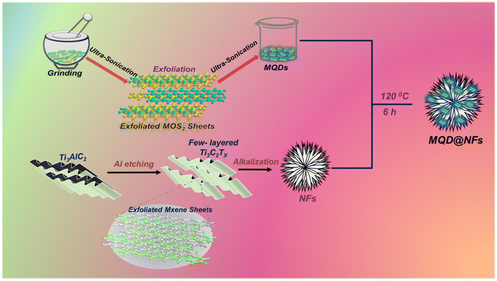
The following chemicals were sourced from Sigma Aldrich: hydrofluoric acid (HF), molybdenum sulfide (MoS2) (<2 μm), Nafion solution (used as a binder) and lithium fluoride (LiF). Ti3AlC2 (precursor MAX phase) was acquired from Nano Research Elements, Haryana, India. Hydrochloric acid (HCl), ethanol (C2H5OH), sulfuric acid (H2SO4), potassium hydroxide (KOH), isopropyl alcohol (IPA), and N-methylpyrrolidone (NMP) were procured from the Research lab. Nickel foam was obtained from Research Supporters India (RSI).MoS2 quantum dots (MQDs) were prepared similarly to the previously reported method with minor modifications.26 0.5 g of MoS2 nanosheets were dispersed in 10 mL of NMP to form a solution of 50 mg mL−1. The above solution was poured into a mortar and ground for 1 h. Then, the obtained mixture was ultra-sonicated for 5 h in a 50 mL serum tube. The mixture obtained was further grinded using a mortar pestle for 30 min, followed by ultrasonic exfoliation treatment for 5 h. Additionally, the mixture was centrifuged to separate the supernatant with a mixture of NMP, hexane, and chloroform (1![[thin space (1/6-em)]](https://www.rsc.org/images/entities/char_2009.gif) :
:![[thin space (1/6-em)]](https://www.rsc.org/images/entities/char_2009.gif) 1
1![[thin space (1/6-em)]](https://www.rsc.org/images/entities/char_2009.gif) :
:![[thin space (1/6-em)]](https://www.rsc.org/images/entities/char_2009.gif) 1) at 7000 rpm for 20 min to obtain the supernatant containing MQDs. The obtained black MQDs were stored at room temperature for further experiments.
1) at 7000 rpm for 20 min to obtain the supernatant containing MQDs. The obtained black MQDs were stored at room temperature for further experiments.
Characterizations of the prepared materials
The prepared specimen underwent compression to produce thin films for powder X-ray diffraction (PXRD) analysis under a scan rate of 10° min−1, within the 2θ range of 50° to 900°. Surface imaging of the prepared materials to assess the size, shape, and homogeneity of the catalyst was performed using FE-SEM at 200 kV. High-resolution transmission electron microscopy (HR-TEM) was utilized to verify the morphology and structure of MQD@NFs. XPS was performed to analyze the elemental contributions of the sample through a Thermo Scientific Nexsa G2 Surface Analysis System. FT-IR data were collected using the Perkin-Elmer Spectra GX 2000 FT-IR spectrometer with KBr pellets. Electrochemical analysis, including HER, linear sweep voltammetry (LSV), cyclic voltammetry (CV), and impedance measurements, were conducted by employing the Metrohm Autolab PGSTAT204 at ambient temperature. Nickel foam (1 × 1 cm2 effective area), graphite rod (3 mm diameter), and Ag/AgCl served as the working, counter, and reference electrodes, respectively.Results and discussions
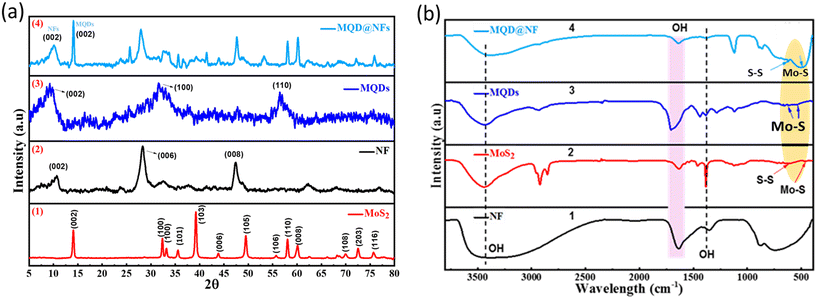
The structure of the as-synthesized nanomaterials was systematically characterized by XRD. The absence of the characteristic band at 2θ = 39° (Fig. S1†), belonging to the (104) plane of MAX phase (Ti3AlC2), confirms the complete elimination of Al layers from Ti3AlC2 and conversion into MXenes.23 Further, in NFs, the XRD patterns followed the same fashion as that of Ti3C2 MXene. These NFs were synthesized through the HF etching methodology and its further modification with alkali (Fig. 2a_2). The crest at 2θ = 10.6° and 28.3°, 32.4°, 41.4°, 47.4°, 62.2°, 68.1°, and 76.9° reveal the successful formation of NFs.24 In the synthesized electrocatalyst MQDs@NFs (Fig. 2a_4), peaks shift from 10.8° to 10.1° due to the introduction of MQDs onto the NFs. Also, the peaks observed at 28.1°, 39.3°, 47.7°, 69.01°, and 75.8° correspond to NFs. Additionally, peaks obtained at 25.7°, 32.5°, 33.8°, 41.5°, 43.9°, 53.4°, and 62.5° belong to MQDs.27,28 As shown in Fig. 2a_1, the pristine MoS2 in bulk form had an evidently dominating diffraction crest at 2θ = 14.1°, which accords with the (002) phase, specifying that the original precursor has a multilayer structure. Additionally, several other peaks located at 2θ = 32.4°, 33.2°, 39.2°, 43.8°, 49.5°, 55.7°, 58.1°, 60.1°, 69.9°, 72.6°, and 75.7° can be observed, which are assigned to the (100), (101), (103), (006), (105), (106), (110), (008), (108), (203), and (116) planes, respectively (JCPDS (37-1492)).25 XRD patterns do not give strong signals or peaks if the materials have a thin or monolayer structure.29 From Fig. 2a_3, it is seen that the spectra contain some very wide and weak diffraction peaks at 2θ values of 9.2°, 25.6°, 32.2°, 37.6°, 41.7°, 44.5°, 55.1°, 56.6°, and 63.7°, which reveals the growth of amorphous molybdenum sulphide nanostructures.30The presence of surface functional moieties in NFs, MoS2, and nanocomposites was confirmed by FT-IR spectroscopy, and the resulting graph is presented in Fig. 2b. The stretching vibrations exhibited an absorption crest at 3481 cm−1, corresponding to the surface hydroxyl groups. Simultaneously, additional peaks of the OH group were observed at 1637 cm−1 and 1374 cm−1, respectively.31 These OH groups originated from water adsorbed on the electrocatalyst's surface, indicating rapid water molecule adsorption by the samples and a promoted OH production via the reaction of photoinduced holes with water molecules. In MoS2, the vibration absorption peaks at 612 cm−1 and 490 cm−1 were assigned to S–S and Mo–S bonds, respectively (Fig. 2b_2), while in MQD@NFs (Fig. 2b_4), these peaks shifted to 618 cm−1 and 498 cm−1 due to the interaction of MQDs with NFs.32–34 The UV-visible range of the synthesized MQDs exhibited a single signal in the UV region at 320 nm (Fig. S2†). The MQDs displayed blue fluorescence upon illumination with a 365 nm UV light (inset of Fig. S2†), with excitation at 320 nm reaching the highest peak intensity at 425 nm.25
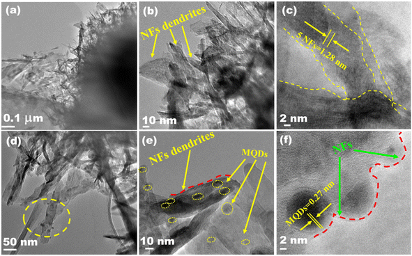
SEM and TEM (Fig. 3 and 4) investigated the morphology of NFs, MQD, and MQD@NFs. KOH-modified MXene (NFs) and MQD@NFs show a marigold flower-like structure of the sub-micron level, containing nano-leaves (Fig. 3a–c and g–i). To be specific, the MQD@NFs possess more rough and irregular morphology than NFs, however. Elemental mapping of NFs is presented in Fig. 3d–f, which confirms the presence of Ti and C. Fig. 3j–n shows the elemental mapping of the as-synthesized MQD@NFs, representing the existence of titanium, molybdenum, carbon, and sulphur. Also, the elemental composition of both NFs and MQD@NFs is shown in Fig. S3.† The development of these nano-dimensional MoS2 quantum dots can be perceived by the sonication-prompted exfoliation of the bulk MoS2 sheets in NMP. The standing waves generated during the ultrasonication process are accepted to trim the lamellar particles, and continuous vibration brings the development of quantum dots, as seen in the given TEM images (Fig. S4†). The HR-TEM images plainly show the size of MoS2 quantum dots between 3 and 11 nm with an average diameter of 7 nm (Fig. S4b†). Under closer examination in TEM images (Fig. 4), the NFs were viewed as consistently decorated with numerous nano-sized MQDs with a typical diameter of around 5.5 nm. The HR-TEM images (depicted in Fig. 4c and f) reveal distinctive lattice fringes with interplanar spacings of 0.27 nm and 0.26 nm, corresponding to the (100) plane of MQDs and (100) plane of NFs, respectively.35,36 Notably, the existing functionalities of NFs provide abundant loading/binding sites for the immobilization of MQDs. Additionally, direct electronic communication enhances the stability of MQDs within the NFs framework.
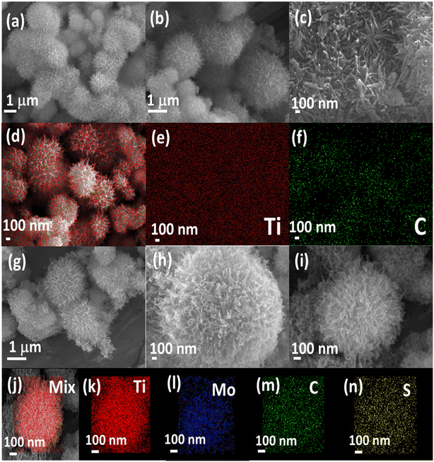 | ||
| Fig. 3 SEM results for (a–c) NFs, (g–i) MQD@NFs, elemental mapping graphs for NFs of mix (d), Ti (e) and C (f), and for MQD@NFs of mix (j), Ti (k), Mo (l), C (m), and S (n). | ||
XPS estimations were performed to procure the elemental composition of the as-synthesized MQD@NFs. As expected, the survey contains a review range of MQD@NFs demonstrating the presence of C, Ti, O, Mo, and S elements (Fig. 5a), which matches properly with previously mentioned maps of different elements of EDX results. Small concentrations of K, F, and Cl components can likewise be observed in NFs in the spectra, predominantly because of the utilization of HCl and LiF etchants during the synthesis process. For Ti 2p spectra, peaks occur at 458.52 eV and 464.25 eV belonging to the 2p3/2 of TiO2 and 2p1/2 of TiO2 in synthesized NFs. It confirms the existence of some chemical bonding between MQDs with –O– carrying groups on NFs and carbon overlays. Apart from having a weak physical connection, the robust interplay among MQDs, NFs, and the carbon layer could remarkably enhance the morphological stability and ion diffusion capability of the material. This enhancement is crucial for elevating the catalytic activity of the synthesized MQD@NFs nanocomposites (Fig. 5b). Also, these peaks shift to 458.30 eV and 464.07 in as-synthesized MQD@NFs.23,36 Furthermore, peak fitting of the Mo 3d range produces two sets of doublet peaks, focused at 227.09 eV, 229.8 eV, and 232.98 eV due to S 2s, Mo 3d5/2 of MoS2, and Mo3d3/2 of MoS2, while the peak at 236.4 eV occurs due to Mo6+ (MoO3) due to surface oxidation of MQDs (Fig. 5c),37,38 convincingly exhibiting the direct electronic interaction between MQDs and NFs. Also, the deconvoluted S 2p peaks displayed four primary peaks at 161.2 eV, 161.9 eV, 163.1 eV, and 164.1 eV, confirming the presence of the divalent S ions in the synthesized MQD@NFs (Fig. 5d).39 The core-level C 1s spectrum of MQD@NFs is split into tri-peaks of energy at 284.6 eV, 286.5 eV, and 288.5 eV, having a place with the C–C, CHx/C–O, and C![[double bond, length as m-dash]](https://www.rsc.org/images/entities/char_e001.gif) O, respectively (Fig. 5e).36 The XPS spectra of the O 1s spectrum consist of bi-components i.e., C–OH/C–O–C (531.9 eV), and C
O, respectively (Fig. 5e).36 The XPS spectra of the O 1s spectrum consist of bi-components i.e., C–OH/C–O–C (531.9 eV), and C![[double bond, length as m-dash]](https://www.rsc.org/images/entities/char_e001.gif) O (530.1 eV) (Fig. 5f).40
O (530.1 eV) (Fig. 5f).40
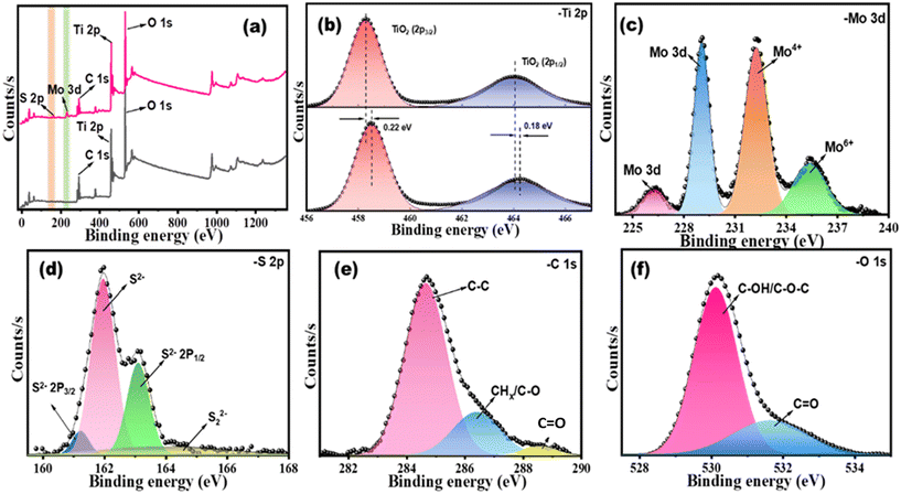 | ||
| Fig. 5 XPS spectra of (a) full survey for MQD@NFs, (b) Ti and (c) Mo comparison before and after doping and (d) S, (e) C and (f) O for MQD@NFs. | ||
Electrochemical experiments
The electrocatalytic activity of as-synthesized MQD@NFs was examined utilizing the three-electrode system. Nickel foam, Ag/AgCl, and graphite rod of 3 mm diameter were employed as working, reference, and counter electrodes. The synthesis of the MQD@NFs working electrode is as follows: (1) 5 mg of MQD@NFs and 1 mL of isopropyl alcohol were taken, and the solution was ultra-sonicated for 10 min. Then, 10 μL of Nafion solution (5%) was added to form the electrocatalyst ink, followed by sonication. The as-prepared electrocatalyst ink was cast drop by drop over nickel foam (1 × 1 cm2) through a pipette and dried overnight at 25 °C (Fig. 6). These measurements were performed in 0.5 M H2SO4 solution. The linear sweep voltammetry technique (LSV) was used to obtain HER activity employing a working electrode at a sweep rate of 5 mV s−1 in a potential window of 0.1 V to −1.5 V vs. RHE. The following equation was used to determine the overpotential ( ) and Tafel slope:41
| η (V) = ERHE − 1.23 V vs. RHE, |
η = b![[thin space (1/6-em)]](https://www.rsc.org/images/entities/char_2009.gif) log(i/i0) + a, log(i/i0) + a, |
 for 12 hours. Electrochemical impedance spectroscopy (EIS) was employed to appraise the charge transfer resistance of working electrodes. This evaluation was conducted with a consistent overpotential covering a frequency spectrum from 10 kHz to 100 mHz, employing an AC bias voltage of 10 mV. The determination of the electrochemical active surface area (ECSA) relied on the double-layer capacitance (Cdl). Moreover, cyclic voltammetry (CV) was performed in a non-faradic region to assess the Cdl value.
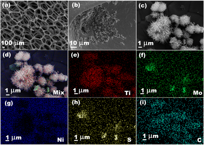 | ||
| Fig. 6 (a–c) SEM images of the MQD@NFs drop-casted on the Ni foam before HER, elemental mapping for (d) mix (e) Ti, (f) Mo, (g) Ni, (h) S and (i) C. | ||
The carbonaceous framework of MXene facilitates a homogenous distribution of MQDs that contributes to enhanced ion diffusion and conductive properties, which may be a reason for excellent electrocatalytic performance. HER activity of the electrocatalysts was performed using cyclic and linear voltammetry techniques. A graphite rod and Ag/AgCl were taken as counter and reference electrodes, respectively, while nickel foam was loaded with MQD@NFs catalyst and used as the working electrode. The CV was first stabilized by an electrocatalyst-modified working electrode at a sweep rate of 100 mV s−1 until it got a steady curve. To minimize the effect of capacitive current, the test was executed at a low sweep rate of 5 mV s−1 in 0.5 M H2SO4. Overpotential is a vital parameter for investigating electrocatalytic activity. It imitates 10% effective photocatalytic water splitting, and the corresponding electrocatalytic H2 evolution activity of the Ni foam, NFs, MQDs, MoS2, and MQD@NFs were examined using the LSV technique shown in Fig. 7a. As depicted, MQD@NFs possess a η10 of 307 mV at 10 mA cm−2 in comparison with bare Ni foam (389 mV), MQDs (354 mV), MoS2 (362 mV), and NFs (349 mV). The high HER activity for MQD@NFs is due to the homogeneous scattering of the active metal sites and synergistic interaction between MQDs and NFs. The inset graph in Fig. 7a shows the performance of the commercially used Pt/C catalyst loaded over Ni foam for comparison with the synthesized catalyst.42 Moreover, the related Tafel curves of the synthesized electrocatalyst were optimized, as represented in Fig. 7b. The Tafel slope of the MQD@NFs is 68.5 mV dec−1, significantly lower in comparison with Ni foam (103.5 mV dec−1), MQDs (84.1 mV dec−1), MoS2 (95.7 mV dec−1), and NFs (89.3 mV dec−1). The smaller Tafel slope is attributed to low power consumption at a high current.43 In other words, a lower applied voltage is needed with a faster reaction rate to reach a given current. Furthermore, the electrocatalytic activity of the synthesized electrocatalyst was also examined using the LSV technique shown at a maximum current density achieved by electrocatalyst (40 mA cm−2), defining the excellent electrocatalyst activity of the MQDS@NFs over other materials (Fig. 7c). The Nyquist plot (depicted in Fig. 7d) illustrates the associated equivalent circuit, where Rs represents the solution resistance, C denotes capacitance, and Rct signifies the charge transfer resistance at the electrochemical interface. A low charge transfer resistance value (18.2 Ω) affirms a brisk reaction rate in the MQD@NFs catalyst. To assess the stability of the MQD@NFs catalyst, a series of 1000 cyclic CV cycles at a sweep rate of 100 mV s−1 was conducted, as shown in Fig. 7e. Minimal changes were observed from the 1st to the 1000th cycle, indicating favorable long-term durability. Apart from electrocatalytic activity, the longevity of the electrocatalyst is one more key to expanding the practical apparatus for H2 production (Fig. 7f). The durability of the synthesized electrocatalyst was determined by chronoamperometry (at cathodic overpotential) through time dependence of the current density for the catalyst at a constant overpotential of 307 mV vs. RHE for 12 h and using a glassy carbon electrode as working electrode (GCE). The anodic current density for MQD@NFs was found to be unaffected, contributing to the stability in the acidic electrolyte after HER. Further, the continuous H2 bubble accumulation and release process on the electrode is shown in Fig. 7f inset.44
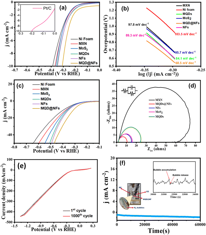 | ||
| Fig. 7 (a) LSV, (b) Tafel plot, (c) LSV at high current density, (d) impedance, (e) 1000 CV cycles, and (f) stability of MQD@NFs. | ||
CV was executed to demonstrate the ECSA of the synthesized electrocatalyst. Cdl values for the electrocatalyst were observed in non-faradic regions at different sweep rates varying from 5 mV to 200 mV (Fig. 8a). The Cdl value achieved for MQD@NFs was 89 μF (Fig. 8b), which is greater in comparison with NFs and MQDs. The high double-layer capacitance (Cdl) value for MQD@NFs reveals the high electrochemical active area for enhanced activity in HER (Fig. 8b). The ECSA serves to illustrate the reactive surface area of the electrode, allowing for comparisons with the intrinsic catalytic performances of other materials and evaluated using the following:
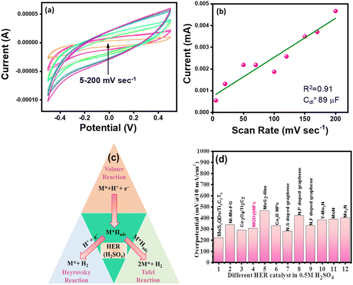 | ||
| Fig. 8 (a) ECSA and (b) linear plot of the MQD@NFs, (c) plausible mechanism, and (d) comparison with other electrocatalysts. | ||
Durability and recyclability of MQD@NFs
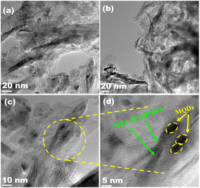
The practical application of electrocatalysts in HER relies not only on their electrochemical activity but also on their stability. To assess the stability of MQD@NFs electrocatalysts, comprehensive characterizations were conducted after the completion of all electrochemical tests. Morphological alterations in the MQD@NFs nanostructure electrocatalyst were analyzed through SEM and HR-TEM imaging after the HER experiments. Surface morphology and elemental composition were observed through SEM analysis of Ni foam loaded with electrocatalyst after (Fig. S5†) HER experiments. Furthermore, elemental mapping and EDX analysis confirmed that the electrocatalyst morphology remained unchanged following HER. After the experiments, the electrocatalyst still has the same morphology and no deterioration. Fig. 9 illustrates the uniform dispersion and orderly arrangement of MQD@NFs, which aligns well with the previously captured TEM results. This examination highlights commendable structural robustness concerning the performance in the context of HER.Conclusion
Interestingly, we have developed an effective method to synthesize MQD@NFs using a simple hydrothermal process followed by calcination. The formation of MQDs@NFs was confirmed by XRD analysis, while SEM and TEM surveys confirmed the uniform deposition of MQDs on NFs and their morphological analysis. MQD@NFs display prevalent HER activity with a small overpotential of 307 mV at 10 mA cm−2 and a Tafel slope of 68.5 mV dec−1. The alkalized NFs not only provide the oxygen-containing functional groups for MQDs but also maintain the size due to the space confinement effect among the NFs. The electrocatalyst represents excellent activity and stability in 0.5 M H2SO4. No morphological changes have been observed in the electrocatalyst after HER, which defines its stability. This non-noble metal-based, environment-friendly composite nanostructure has great potential for water splitting in low pH solutions. The work conveys a facile, robust, and promising methodology for synthesizing homogeneously arranged electrocatalysts for HER activity.Conflicts of interest
Authors declare no conflicts of interest.Acknowledgements
This manuscript corresponds to communication number 82/2024 from CSIR-CSMCRI. The authors would like to thank AESD & CIF, CSIR-CSMCRI, Bhavnagar, for assistance with the instrumentation facilities.References
- S. Xu, H. Zhao, T. Li, J. Liang, S. Lu, G. Chen, S. Gao, A. M. Asiri, Q. Wu and X. Sun, Iron-Based Phosphides as Electrocatalysts for the Hydrogen Evolution Reaction: Recent Advances and Future Prospects, J. Mater. Chem. A, 2020, 8(38), 19729–19745 RSC.
- B. Jiang, T. Yang, T. Wang, C. Chen, M. Yang, X. Yang, J. Zhang and Z. Kou, Edge Stimulated Hydrogen Evolution Reaction on Monodispersed MXene Quantum Dots, Chem. Eng. J., 2022, 442, 136119 CrossRef CAS.
- X. Chen, X. Zhai, J. Hou, H. Cao, X. Yue, M. Li, L. Chen, Z. Liu, G. Ge and X. Guo, Tunable Nitrogen-Doped Delaminated 2D MXene Obtained by NH3/Ar Plasma Treatment as Highly Efficient Hydrogen and Oxygen Evolution Reaction Electrocatalyst, Chem. Eng. J., 2021, 420, 129832 CrossRef CAS.
- S. Anantharaj, S. R. Ede, K. Sakthikumar, K. Karthick, S. Mishra and S. Kundu, Recent Trends and Perspectives in Electrochemical Water Splitting with an Emphasis on Sulfide, Selenide, and Phosphide Catalysts of Fe, Co, and Ni: A Review, ACS Catal., 2016, 6(12), 8069–8097 CrossRef CAS.
- T. J. Meyer, The Art of Splitting Water, Nature, 2008, 451(7180), 778–779 CrossRef CAS PubMed.
- A. Gasparotto, C. Maccato, C. Sada, G. Carraro, D. I. Kondarides, S. Bebelis, A. Petala, A. la Porta, T. Altantzis and D. Barreca, Controlled Surface Modification of ZnO Nanostructures with Amorphous TiO 2 for Photoelectrochemical Water Splitting, Adv. Sustainable Syst., 2019, 3(9), 1900046 CrossRef CAS.
- J. Zhang, Y. Zhao, X. Guo, C. Chen, C.-L. Dong, R.-S. Liu, C.-P. Han, Y. Li, Y. Gogotsi and G. Wang, Single Platinum Atoms Immobilized on an MXene as an Efficient Catalyst for the Hydrogen Evolution Reaction, Nat. Catal., 2018, 1(12), 985–992 CrossRef CAS.
- T. F. Jaramillo, K. P. Jørgensen, J. Bonde, J. H. Nielsen, S. Horch and I. Chorkendorff, Identification of Active Edge Sites for Electrochemical H 2 Evolution from MoS 2 Nanocatalysts, Science, 2007, 317(5834), 100–102 CrossRef CAS PubMed.
- S. Kamila, B. Mohanty, A. K. Samantara, P. Guha, A. Ghosh, B. Jena, P. V. Satyam, B. K. Mishra and B. K. Jena, Highly active 2D layered MoS 2-rGO hybrids for energy conversion and storage applications, Sci. Rep., 2017, 7(1), 1–3 CrossRef CAS PubMed.
- S. A. Ali, S. Majumdar, P. K. Chowdhury, N. Alhokbany and T. Ahmad, Photoinduced Hole Trapping in MoSe2–MoS2 Nanoflowers/ZnO Nanosheets S-Scheme Conduit for Ultrafast Charge Transfer during Hydrogen Evolution, ACS Appl. Energy Mater., 2024, 7(7), 2881–2895 CrossRef CAS.
- N. Xue and P. Diao, Composite of Few-Layered MoS 2 Grown on Carbon Black: Tuning the Ratio of Terminal to Total Sulfur in MoS 2 for Hydrogen Evolution Reaction, J. Phys. Chem. C, 2017, 121(27), 14413–14425 CrossRef CAS.
- S. Niu, J. Cai and G. Wang, Two-Dimensional MOS2 for Hydrogen Evolution Reaction Catalysis: The Electronic Structure Regulation, Nano Res., 2021, 14(6), 1985–2002 CrossRef CAS.
- A. Mehtab, S. A. Ali, P. P. Ingole, Y. Mao, S. M. Alshehri and T. Ahmad, MoS2 nanoflower-deposited g-C3N4 nanosheet 2D/2D heterojunction for efficient photo/electrocatalytic hydrogen evolution, ACS Appl. Energy Mater., 2023, 6(23), 12003–12012 CrossRef CAS.
- X. Hao, Z. Jin, H. Yang, G. Lu and Y. Bi, Peculiar Synergetic Effect of MoS 2 Quantum Dots and Graphene on Metal-Organic Frameworks for Photocatalytic Hydrogen Evolution, Appl. Catal., B, 2017, 210, 45–56 CrossRef CAS.
- J. Verma and S. Goel, Cost-effective electrocatalysts for hydrogen evolution reactions (HER): challenges and prospects, Int. J. Hydrogen Energy, 2022, 47(92), 38964–38982 CrossRef CAS.
- Z. Liang, Y. Guo, Y. Xue, H. Cui and J. Tian, 1T-Phase MoS 2 Quantum Dots as a Superior Co-Catalyst to Pt Decorated on Carbon Nitride Nanorods for Photocatalytic Hydrogen Evolution from Water, Mater. Chem. Front., 2019, 3(10), 2032–2040 RSC.
- S. K. Raj, V. Sharma, D. N. Srivastava and V. Kulshrestha, In-situ evolution of bimetallic Fe/Ni/Co nanohybrids on MXene for improved electrocatalytic oxygen evolution reaction, Int. J. Hydrogen Energy, 2023, 48(96), 37732–37745 CrossRef CAS.
- S. A. Ali and T. Ahmad, Enhanced hydrogen generation via overall water splitting using novel MoS2-BN nanoflowers assembled TiO2 ternary heterostructures, Int. J. Hydrogen Energy, 2022, 48(58), 22044–22059 CrossRef.
- S. G. Peera, R. Koutavarapu, L. Chao, L. Singh, G. Murugadoss and G. Rajeshkhanna, 2D MXene nanomaterials as electrocatalysts for hydrogen evolution reaction (HER): A review, Micromachines, 2022, 13(9), 1499 CrossRef PubMed.
- J. Liu, Y. Liu, D. Xu, Y. Zhu, W. Peng, Y. Li, F. Zhang and X. Fan, Hierarchical “nanoroll” like MoS2/Ti3C2Tx hybrid with high electrocatalytic hydrogen evolution activity, Appl. Catal., B, 2019, 241, 89–94 CrossRef CAS.
- B. Mohanty, L. Giri and B. K. Jena, MXene-derived quantum dots for energy conversion and storage applications, Energy Fuels, 2021, 35(18), 14304–14324 CrossRef CAS.
- S. K. Raj and V. Kulshrestha, Progress in 2D Nanomaterial Composites Membranes for Water Purification and Desalination, in 2D nanomaterials for energy and environmental sustainability, Springer Nature Singapore, Singapore, 2022, pp. 125–148 Search PubMed.
- L. Chen, J. Liang, Q. Zhang, X. Hu, W. Peng, Y. Li, F. Zhang and X. Fan, Quasi Zero-Dimensional MoS2 Quantum Dots Decorated 2D Ti3C2Tx MXene as Advanced Electrocatalysts for Hydrogen Evolution Reaction, Int. J. Hydrogen Energy, 2022, 47(19), 10583–10593 CrossRef CAS.
- Y. Guo and J. Li, MoS2 Quantum Dots: Synthesis, Properties and Biological Applications, Mater. Sci. Eng., C, 2020, 109, 110511 CrossRef CAS PubMed.
- S. K. Raj, G. R. Bhadu, P. Upadhyay and V. Kulshrestha, Three-Dimensional Ni/Fe Doped Graphene Oxide @ MXene Architecture as an Efficient Water Splitting Electrocatalyst, Int. J. Hydrogen Energy, 2022, 47(99), 41772–41782 CrossRef CAS.
- Y. Dong, Z.-S. Wu, S. Zheng, X. Wang, J. Qin, S. Wang, X. Shi and X. Bao, Ti 3 C 2 MXene-Derived Sodium/Potassium Titanate Nanoribbons for High-Performance Sodium/Potassium Ion Batteries with Enhanced Capacities, ACS Nano, 2017, 11(5), 4792–4800 CrossRef CAS PubMed.
- D. Gopalakrishnan, D. Damien and M. M. Shaijumon, MoS 2 Quantum Dot-Interspersed Exfoliated MoS 2 Nanosheets, ACS Nano, 2014, 8(5), 5297–5303 CrossRef CAS PubMed.
- X. Wang, H. Li, H. Li, S. Lin, W. Ding, X. Zhu, Z. Sheng, H. Wang, X. Zhu and Y. Sun, 2D/2D 1T-MoS2/Ti3C2 MXene heterostructure with excellent supercapacitor performance, Adv. Funct. Mater., 2020,(15), 0190302 CrossRef CAS.
- P. Lian, Y. Dong, Z.-S. Wu, S. Zheng, X. Wang, S. Wang, C. Sun, J. Qin, X. Shi and X. Bao, Alkalized Ti3C2 MXene Nanoribbons with Expanded Interlayer Spacing for High-Capacity Sodium and Potassium Ion Batteries, Nano Energy, 2017, 40, 1–8 CrossRef CAS.
- J. Guo, R. Peng, H. Du, Y. Shen, Y. Li, J. Li and G. Dong, The Application of Nano-MoS2 Quantum Dots as Liquid Lubricant Additive for Tribological Behavior Improvement, Nanomaterials, 2020, 10(2), 200 CrossRef CAS PubMed.
- D. Dinda, Md. E. Ahmed, S. Mandal, B. Mondal and S. K. Saha, Amorphous Molybdenum Sulfide Quantum Dots: An Efficient Hydrogen Evolution Electrocatalyst in Neutral Medium, J. Mater. Chem. A, 2016, 4(40), 15486–15493 RSC.
- Y. Jiang, T. Sun, X. Xie, W. Jiang, J. Li, B. Tian and C. Su, Oxygen-functionalized ultrathin Ti3C2Tx MXene for enhanced electrocatalytic hydrogen evolution, ChemSusChem, 2019,(7), 1368–1373 CrossRef CAS PubMed.
- Y. Li, X. Wang, M. Liu, H. Luo, L. Deng, L. Huang, S. Wei, C. Zhou and Y. Xu, Molybdenum Disulfide Quantum Dots Prepared by Bipolar-Electrode Electrochemical Scissoring, Nanomaterials, 2019, 9(6), 906 CrossRef CAS PubMed.
- F. Maugé, J. Lamotte, N. S. Nesterenko, O. Manoilova and A. A. Tsyganenko, FT-IR study of surface properties of unsupported MoS2, Catal. Today, 2001, 70(1–3), 271–284 CrossRef.
- J. Yang, Q. Zhu, Z. Xie, Y. Wang, J. Wang, Y. Peng, Y. Fang, L. Deng, T. Xie and L. Xu, Enhancement Mechanism of Photocatalytic Activity for MoS2/Ti3C2 Schottky Junction: Experiment and DFT Calculation, J. Alloys Compd., 2021, 887, 161411 CrossRef CAS.
- Q. Liu, C. Hu and X. Wang, A Facile One-Step Method to Produce MoS 2 Quantum Dots as Promising Bio-Imaging Materials, RSC Adv., 2016, 6(30), 25605–25610 RSC.
- H. Huang, Y. Xue, Y. Xie, Y. Yang, L. Yang, H. He, Q. Jiang and G. Ying, MoS 2 Quantum Dot-Decorated MXene Nanosheets as Efficient Hydrogen Evolution Electrocatalysts, Inorg. Chem. Front., 2022, 9(6), 1171–1178 RSC.
- K. Ojha, S. Saha, S. Banerjee and A. K. Ganguli, Efficient Electrocatalytic Hydrogen Evolution from MoS 2-Functionalized Mo 2 N Nanostructures, ACS Appl. Mater. Interfaces, 2017, 9(23), 19455–19461 CrossRef CAS PubMed.
- B. Mohanty, A. Mitra, B. Jena and B. K. Jena, MoS 2 Quantum Dots as Efficient Electrocatalyst for Hydrogen Evolution Reaction over a Wide PH Range, Energy Fuels, 2020, 34(8), 10268–10275 CrossRef CAS.
- S. Zhang, H. Yang, H. Gao, R. Cao, J. Huang and X. Xu, One-Pot Synthesis of CdS Irregular Nanospheres Hybridized with Oxygen-Incorporated Defect-Rich MoS 2 Ultrathin Nanosheets for Efficient Photocatalytic Hydrogen Evolution, ACS Appl. Mater. Interfaces, 2017, 9(28), 23635–23646 CrossRef CAS PubMed.
- S. K. Raj, B. Choudhary, A. Yadav, R. Patidar, A. Mishra and V. Kulshrestha, Green-Synthesized, PH-Stable and Biocompatible Carbon Nanosensor for Fe3+: An Experimental and Computational Study, Heliyon, 2022, 8(4), e09259 CrossRef CAS PubMed.
- S. K. Raj, Kirti, V. Sharma, D. N. Srivastava and V. Kulshrestha, Single-Step Synthesis of Well-Ordered Hierarchical Nickel Nanostructures for Boosting the Oxygen Evolution Reaction, Energy Fuels, 2022, 36(22), 13786–13795 CrossRef CAS.
- G. R. Bhadu, B. Parmar, P. Patel, J. C. Chaudhari and E. Suresh, Controlled Assembly of Cobalt Embedded N-Doped Graphene Nanosheets (Co@NGr) by Pyrolysis of a Mixed Ligand Co(II) MOF as a Sacrificial Template for High-Performance Electrocatalysts, RSC Adv., 2021, 11(34), 21179–21188 RSC.
- A. Han, S. Jin, H. Chen, H. Ji, Z. Sun and P. Du, A robust hydrogen evolution catalyst based on crystalline nickel phosphide nanoflakes on three-dimensional graphene/nickel foam: high performance for electrocatalytic hydrogen production from pH 0–14, J. Mater. Chem., 2015, 3(5), 1941–1946 RSC.
- H. Dong, C. Liu, H. Ye, L. Hu, B. Fugetsu, W. Dai, Y. Cao, X. Qi, H. Lu and X. Zhang, Three-dimensional nitrogen-doped graphene supported molybdenum disulfide nanoparticles as an advanced catalyst for hydrogen evolution reaction, Sci. Rep., 2015, 5(1), 1 Search PubMed.
- J. Xie, J. Zhang, S. Li, F. Grote, X. Zhang, H. Zhang, R. Wang, Y. Lei, B. Pan and Y. Xie, Controllable disorder engineering in oxygen-incorporated MoS2 ultrathin nanosheets for efficient hydrogen evolution, J. Am. Chem. Soc., 2013, 135(47), 17881–17888 CrossRef CAS PubMed.
- J. Xie, H. Zhang, S. Li, R. Wang, X. Sun, M. Zhou, J. Zhou, X. W. Lou and Y. Xie, Defect-rich MoS2 ultrathin nanosheets with additional active edge sites for enhanced electrocatalytic hydrogen evolution, Adv. Mater., 2013, 25(40), 5807–5813 CrossRef CAS PubMed.
- S. Muralikrishna, K. Manjunath, D. Samrat, V. Reddy, T. Ramakrishnappa and D. H. Nagaraju, Hydrothermal synthesis of 2D MoS2 nanosheets for electrocatalytic hydrogen evolution reaction, RSC Adv., 2015, 5(109), 89389–89396 RSC.
- A. Irshad and N. Munichandraiah, Electrodeposited Nickel–Cobalt–Sulfide Catalyst for the Hydrogen Evolution Reaction, ACS Appl. Mater. Interfaces, 2017, 9(23), 19746–19755 CrossRef CAS PubMed.
- Y. Shi, Y. Zhou, D. R. Yang, W. X. Xu, C. Wang, F. B. Wang, J. J. Xu, X. H. Xia and H. Y. Chen, Energy level engineering of MoS2 by transition-metal doping for accelerating hydrogen evolution reaction, J. Am. Chem. Soc., 2017, 139(43), 15479–15485 CrossRef CAS PubMed.
- Y. Kang, Y. Gong, Z. Hu, Z. Li, Z. Qiu, X. Zhu, P. M. Ajayan and Z. Fang, Plasmonic hot electron enhanced MoS 2 photocatalysis in hydrogen evolution, Nanoscale, 2015, 7(10), 4482–4488 RSC.
Footnotes |
| † Electronic supplementary information (ESI) available. See DOI: https://doi.org/10.1039/d4lf00106k |
| ‡ Contributed equally. |
| This journal is © The Royal Society of Chemistry 2024 |

