
 Open Access Article
 This Open Access Article is licensed under a Creative Commons Attribution-Non Commercial 3.0 Unported Licence
Synthesis of an imine-type nickel complex and investigation of its electrocatalytic activity for H2 evolution†
Lan H. Le ,
Ngoc H. Pham,
Phong D. Tran and
Tung H. To*
,
Ngoc H. Pham,
Phong D. Tran and
Tung H. To*
University of Science and Technology of Hanoi, Vietnam Academy of Science and Technology, 18 Hoang Quoc Viet, Hanoi, Vietnam. E-mail: to-hai.tung@usth.edu.vn
First published on 24th January 2025
Abstract
We report on the synthesis and characterization of an imine-type nickel complex produced via the complexation of an in situ generated 2-(iminomethyl)phenol ligand with NiII ion. The use of this complex as an electrocatalyst for H2 evolution in a DMF solution, with acetic acid as the proton source, was investigated in detail, employing both experimental analyses (electrochemical analysis, spectroscopy analysis) and theoretical analysis (plateau current analysis). The overpotential required for H2 evolution is about 590 mV with a faradaic efficiency of 49% after 3 hours bulk electrolysis, competing with the two-electron reduction of free-imine groups in the ligand. The maximal TOF was estimated to be about 12![[thin space (1/6-em)]](https://www.rsc.org/images/entities/char_2009.gif) 860 s−1 on the basis of a CECE mechanism.
860 s−1 on the basis of a CECE mechanism.
Introduction
In the 21st century, the search for alternative energies to replace traditional fossil fuels is gaining great attention from scientists, energy companies, and countries around the world. Among the potential candidates, hydrogen (H2) is identified as a clean, renewable energy source and could become a key energy carrier in the future economy.1,2 However, the production of hydrogen on a large scale still faces significant challenges.2,3 From a technical point of view, the production of green H2 from water electrolysis faces difficulties because of slow kinetics; thus, the identification of viable catalysts is highly demanded.4 Catalysts made of noble metals such as Pt and IrO2 are excellent in terms of catalytic performance, but their rarity likely limits their use in industrial H2 production. Hence, an ongoing active research direction has focused on identifying alternative catalysts that can be produced using earth-abundant elements.5–11 Inspired by the natural hydrogenases,12 which efficiently catalyses the reduction of protons into hydrogen, numerous studies have focused on designing molecular catalysts using first-row transition metals (Fe, Co, and Ni) for catalytic H2 evolution.13–16 Among the nickel-based molecular catalysts that have been reported, we can mention several promising candidates such as nickel–polyaza macrocyclic complexes;17 nickel–polypyridine complexes,16,17 nickel–phosphine complexes17 or nickel–thiolate complexes.17 Although the salen compound, N,N′-ethylenebis(salicylimine), is one of the well-known ligands in the coordination chemistry, nickel–salen complexes have not been studied intensively as catalysts for the H2 evolution reaction.18–23 One reason for the lack of interest in salen-type ligands may be the difficulty in tuning their structure. For instance, it is possible to (i) add functional groups (electron withdrawing or electron donating groups); (ii) use phosphorus or sulfur as the donating groups instead of oxygen in the traditional salen ligands (N2O2), or (iii) change the length of the conventional 2-carbon bridging linkage in the salen structure. In 2016, Zhan et al. reported on the synthesis of a nickel–diiminodiphosphine complex that catalysed H2 evolution with moderate turnover frequencies (TOF) of 204 and 1327 per hour in acetonitrile and in an aqueous electrolyte of pH 7, respectively.22 Robert et al. reported on a nickel complex with an N2P salen ligand showing a faradaic efficiency (FE) of 85%, calculated based on 4 hours bulk electrolysis in the presence of HClO4 acid.18 Regarding the ligand with sulfur donors, to the best of our knowledge, no report about this modification is available, perhaps due to the difficulties in the synthesis of these ligands. Sulfur groups are considered as the soft nucleophilic reagents in the condensation reaction generating salen compounds, and they always tend to conduct the cyclization instead of remaining as free donors such as oxygen or phosphorus groups.24,25Regarding the linkage alteration, the length of the bridging ligand has been mainly kept with the traditional 2-carbon linkage. An alternation of this bridging ligand length was not popular. In 2020, Liu et al. described a nickel complex with a five-coordinate N3O2 salen ligand containing a 3-carbon linkage.21 However, the amended ligand did not offer an impressive H2 evolution catalytic activity. Actually, an FE value of 67% was achieved after 5 hours bulk electrolysis at −1.60 V vs. Fc+/0 (with an overpotential of 340 mV).
Recently, we reported the synthesis of cobalt dinuclear complexes using a “short” salen ligand containing a 1-carbon linkage. These complexes showed attractive H2 evolution activity in DMF solution employing acetic acid as the proton resource; an overpotential of 470 mV was required and FE of 85–95% was obtained after 5 hours bulk electrolysis.26 Herein, we report the synthesis, structural characterization and investigation of the catalytic H2 evolution activity of a nickel complex with a “short” salen ligand.
Experimental
All reagents and solvents were purchased from commercial sources and used without any additional purification. All reactions were performed in oven-dried glassware. 1H and 13C-NMR spectra were recorded in a deuterated solvent (dimethyl sulfoxide DMSO-d6) on Bruker Avance Neo 600 spectrometers (600 and 150 MHz, respectively). Chemical shifts are reported in parts per million (ppm) from tetramethylsilane (TMS) with the solvent resonance as an internal standard. Splitting patterns are designated as “s, d, t, q, and m” to indicate “singlet, doublet, triplet and multiplet”, respectively. UV-vis spectra were recorded on an Agilent Cary 3500 compact instrument using a 1 cm quartz cuvette. Samples were prepared in the DMF solution. Raman spectra were recorded on a HORIBA LabRAM HR Evolution Raman Microscope in the region from 100 to 3000 cm−1, using a 532 nm diode laser with a 0.1% filter. Fourier-transform infrared spectroscopy measurements were conducted on a Thermo Scientific Nicolet iS50 spectrometer in the region from 525 to 4000 cm−1 using the Attenuated Total Reflection (ATR) mode. Powder samples were used for the Raman and IR measurements. Elemental analysis was carried out using the Flash 2000 (ThermoFisher) equipment. ICP-MS was measured using the Thermo Scientific iCAP RQ, and calibration curves were established for the concentration range relevant to the samples.The pre-ligand N,N′-bis(salicylidene)-phenylmethanediamine (M) was prepared following the procedure described in our previous study.26
Synthesis of [NiL]
10 mL ethanolic solution of NiCl2·6H2O (1.44 g; 6.06 mmol; 1.0 eq. mol) was added dropwise into 15 mL of suspension in ethanol containing the pre-ligand M (2.0 g; 6.06 mmol; 1.0 eq. mol) and triethylamine (6 mL). The orange precipitate appeared after 30 minutes and the reaction mixture was stirred continuously at the ambient temperature for 7 hours. The product was filtered and washed with ethanol, diethyl ether and acetone:dichloromethane mixture (1:1/v/v), and then dried in vacuo to obtain the orange powder (1.44 g; 77%).
1H-NMR (600 MHz, DMSO-d6) δ 8.56 (s, 2H, –NH); 7.76 (d, J = 11.7 Hz, 2H, –CH![[double bond, length as m-dash]](https://www.rsc.org/images/entities/char_e001.gif) NH); 7.32 (dd, J = 7.8, 1.9 Hz, 2H, Har); 7.14 (ddd, J = 8.6, 6.9, 1.8 Hz, 2H, Har); 6.66 (d, J = 8.5 Hz, 2H, Har); 6.54–6.48 (m, 2H, Har).
NH); 7.32 (dd, J = 7.8, 1.9 Hz, 2H, Har); 7.14 (ddd, J = 8.6, 6.9, 1.8 Hz, 2H, Har); 6.66 (d, J = 8.5 Hz, 2H, Har); 6.54–6.48 (m, 2H, Har).
13C-NMR (151 MHz, DMSO-d6) δ 164.53; 162.86; 133.39; 133.27; 120.59; 120.20; 114.41.
Controlled-potential electrolysis (CPE) in organic media was conducted using an air-tight glass double compartment cell wherein two compartments were separated by a frit. The working compartment was fitted with a graphite electrode (working surface area = 2.0 cm2) and an Ag/AgCl reference electrode. The auxiliary compartment was fitted with a Pt counter electrode. Bulk electrolysis solutions were purged with N2 gas for 1 hour to eliminate the dissolved O2.
H2 production was quantified by gas chromatography. The gaseous product was manually sampled and analysed using a PerkinElmer Clarus 690 gas chromatographer. The analysis setup represented a 5 min method with 100 °C injection, nitrogen gas flow was 12 mL min−1, Restek ShinCarbon ST Micropacked GC Column and Thermal Conductivity Detector (TCD) was set at 200 °C and −40 mA current.
Results and discussion
Synthesis and characterization of NiL complex
The nickel complex (NiL) was prepared via a one-step reaction consisting of equimolar amounts of nickel(II) chloride and pre-ligand (M) in the presence of triethylamine. The reaction was kept overnight, the reaction completion was monitored by TLC. The crude compound was obtained in the form of an orange powder, which was then collected by filtration, washed intensively with ethanol, diethyl ether and an acetone–dichloromethane mixture to obtain the pure orange complex (NiL) (Scheme 1). The formation of the product was confirmed by physical spectroscopic analyses. In the 1H-NMR spectrum, the decomposition of pre-ligand (M) could be observed obviously throughout the lack of aromatic proton signals when the –CHC6H5 group at the salen-ligand bridge was removed (Fig. S1a†). The –NH protons of the imine group showed broad singlet peaks at 8.56 ppm whereas –CH– protons showed peaks at 7.77 ppm appearing in the doublet multiplicity. With the coupling constant J = 12.0 Hz, we could also determine the configuration of the –CHNH group, which is in the cis form. In the 13C-NMR spectrum, the resonance signals of imine carbon atoms were still at 164.5 ppm. However, there was a slight shift from 160.0 ppm to nearly 162.8 ppm for the carbon atoms in the aromatic ring, which were bonded to the oxygen atoms. This change was attributed to the influence of the Ni metal center, which reduced the electron density around the carbon atom, causing the resonance signal shift to the downfield region. Besides that, the signal of N–C–N bridging carbon initially found at 89.5 ppm in the free pre-ligand, disappeared in the NiL complex together with the absence of 6 other aromatic carbon signals. These observations further confirmed the decomposition of the salen ligand to imine compound during the reaction with NiII ion (Fig. S1b†). The formation of this imine complex was indicated more clearly on the basis of infrared spectrum analysis. The appearance of the vibration at 3303 cm−1 characterized the stretching vibration of the –NH group. The vibration of the CNH imine group was indicated at 1614 cm−1 having no difference in comparison to that on the ligand (1615 cm−1) (Fig. S2†). The full Raman spectra of the ligand and the (NiL) complex showed several similarities. Especially, two bands found at 448 cm−1 and 482 cm−1 were attributed to the Ni–O stretching vibration (Fig. S3†). This evidence reinforced the formation of the Ni–O bond in the complex structure.
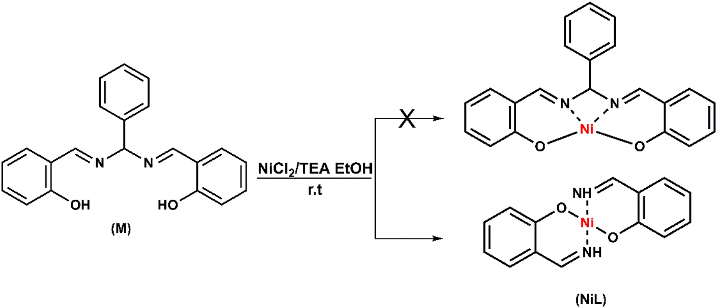 | ||
| Scheme 1 Synthesis of complex NiL. | ||
NiL complex was also investigated by the molecular absorption spectroscopy (Fig. 1). The π to π* intra-ligand transitions of the aromatic system and the imine group –CHN in the complex were observed at 266 nm and 323 nm, respectively.27 There was a shoulder at 337 nm with a molar absorptivity of 9028 L mol−1 cm−1, which was assigned to the charge–transfer transition in the nickel(II) Schiff-base complex.27 In the NiCl2 precursor spectrum, the d–d transition of nickel could be observed at 408 nm with a low molar absorptivity of 14 L mol−1 cm−1. However, this d–d transition changed to metal-to-ligand charge transfer in the NiL complex as a significantly greater molar absorptivity (5245 L mol−1 cm−1) was determined (Fig. 1, zone 2).27 In our previous study, we indicated that when the imine groups participated in the complexation with cobalt ions, the absorption peak of the ligand at 321 nm (π to π* transition of imine groups) experienced a red-shift to a higher wavelength (e.g. 378 and 400 nm).26 However, in the case of the nickel complex, when compared with previous nickel Schiff-base complexes, this transition still remained at the same wavelength.27
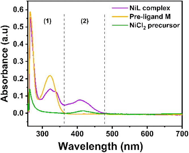 | ||
| Fig. 1 UV-vis spectra recorded for NiL complex, Ni-precursor and the free ligand dissolved in DMF solution. | ||
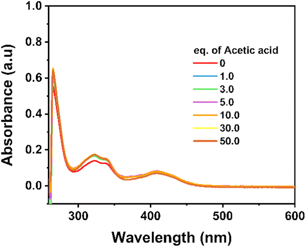
The eventual chemical decomposition of the NiL complex was investigated in the presence of two acidic environments: acetic acid AA (pKa of 13.5 in DMF) and trifluoroacetic acid TFA (pKa of 6.0 in DMF) (Fig. 2). In the case of a weaker acid, the absorption peak was intact when increasing the amount of acid up to 70 equivalent moles suggesting that the complex was stable in this acidic environment (Fig. 2a and b).
 | ||
| Fig. 2 UV-vis spectra recorded for NiL complex dissolved in DMF in the presence of acetic acid (a and b) and trifluoroacetic acid (c and d). | ||
In the shape contrast, when the TFA proton source was added, the complex solution gradually lost its colour (Fig. 2c and S4a†). When 1 or 2 molars equivalent of TFA was added, the NiL compound could be protonated, but this protonation did not decompose the complex. Indeed, unchanged UV-vis spectra were recorded (Fig. 2d). However, adding up to 4 equivalent molars of TFA caused the complete degradation of the NiL complex, releasing the free ligand and nickel trifluoroacetate salt (Fig. 2d). As a result, the MLCT band completely disappeared and the absorption spectrum of the initial ligand re-appeared (Fig. S4b†). Finally, the elemental analysis and ICP-MS analysis showed the similarity between the calculated and actually found elemental composition, thereby further confirming the complex structure.
Electrochemical properties and electrocatalytic H2 evolution activity
The electrochemical properties of the NiL complex were first investigated in an organic electrolyte, namely the DMF solvent containing 0.1 M TBATFB as the electrolyte support. Molar concentration of this compound was prepared at 1 mM. Cyclic voltammograms were recorded on a glassy carbon electrode with the potential scan rate of 50 mV s−1 (Fig. 3).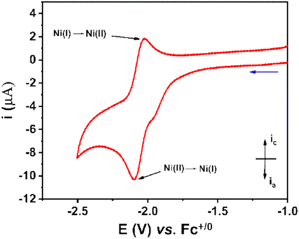 | ||
| Fig. 3 Cyclic voltammograms recorded on a stationary glassy carbon electrode for the 1 mM NiL in DMF solution. The potential scan rate was 50 mV s−1. | ||
A quasi-reversible redox event at E1/2 of −2.06 V vs. Fc+/0 with peak-to-peak separation ΔE of 62 mV was observed, which was assigned to the NiII/NiI redox couple. In comparison to the NiCl2 precursor, the NiL complex displayed the NiII/NiI redox couple at more cathodic potential (−2.10 V versus −1.73 V vs. Fc+/0) (Fig. S5†). This change could be explained by the fact that the electron donation of L ligand enriched the electron density in the NiII center within the NiL complex, hence the reduction of NiL required a more cathodic potential. Additionally, there is a small reduction shoulder at −1.96 V vs. Fc+/0, which was attributed to the reduction of free-imine groups within the NiL compound.28–30
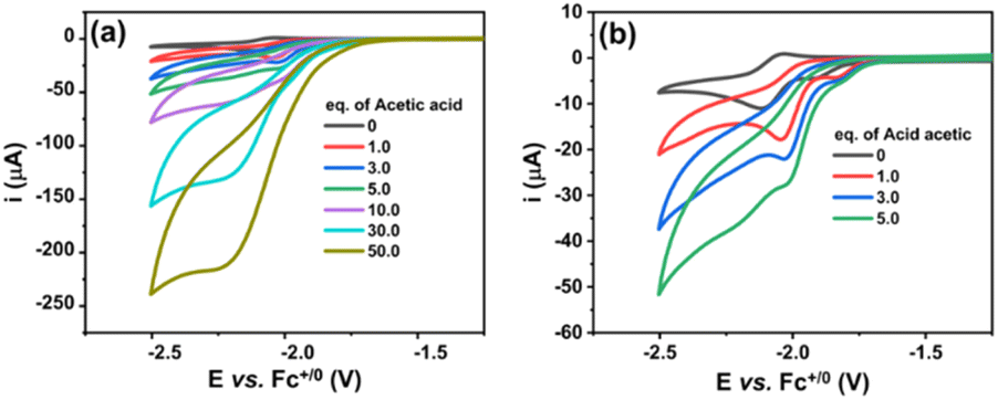
We then investigated the electrocatalytic H2 evolution activities of the NiL complex in the same DMF electrolyte solution in the presence of acetic acid (AA) as the proton source. It can be seen that with the sequent increase of AA concentration (from 0.0 to 50.0 mM), a catalytic wave emerged at a mid-wave potential 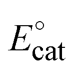 of −2.05 V vs. Fc+/0 (Fig. 4a). This potential is close to that found for the NiII/NiI redox couple in the absence of proton source (Fig. 3). It suggests that the reduced NiI intermediate could involve in the catalysis of H2 evolution. We note that this intermediate was usually found for nickel complexes such as nickel–salen;31 nickel–thiosemicarbazone;32 nickel–pyridylthiolate33 or nickel–thioether.34 It is noted that when adding 1 equivalence of acetic acid into the complex solution, the reduction peak shifted toward the less cathodic potential (Fig. 4b). This phenomenon implies that the reduction of NiII center within the NiL complex required lower reducing energy in the presence of a proton.
 | ||
| Fig. 4 Cyclic voltammograms recorded on a glassy carbon electrode for a 1 mM solution of NiL in DMF with the increasing amount of acetic acid added (a) and (b) shows the cyclic voltammograms recorded when adding a low concentration of acetic acid. The potential scan rate was 50 mV s−1. | ||
It can be explained that the protonation first occurred at the imine groups leading to the delocalization of electrons in the conjugated system, which decreased the electron density in the NiII center and therefore shifted its reduction to lower reducing potential (Scheme 2). In other words, the H2 evolution occurred on the NiL catalyst via a CE mechanism wherein C implied the chemical step and E implied the electron-transfer step. We note that the CE mechanism has been evoked for other nickel complexes, such as nickel–pyridylthiolate complex33 or nickel–pyridino diquinoline complex35
 | ||
| Scheme 2 Electron delocalization in the NiL complex induced by the protonation. | ||
To ensure that the proton reduction producing H2 occurred by catalytic activities of homogeneous NiL complex dissolved in solution but not its eventual decomposition products, the “rinse test” being the control experiment was carried out. The glassy carbon electrode, used for recording cyclic voltammograms of a solution containing 1 mM catalyst NiL and 50 mM AA, was taken out and washed intensively with DMF solvent. The electrode was then immersed in a new DMF solution containing 50 mM AA without catalyst NiL. A negligible cathodic current was recorded. This result demonstrated the non-catalytic character of the glassy carbon electrode after being used for the catalysis assay of the NiL complex. In other words, no catalytically active deposit was produced from the NiL solution during the H2 evolution catalytic assay (Fig. S6†). Hence, the catalytic H2 evolution activity was solely generated by the NiL homogeneous catalyst but not its decomposition product. This result is quite consistent with most previous studies reporting on the stability of nickel complexes under electrochemical reduction conditions. It is noted that under the electrochemical oxidation conditions, the electro-decomposition of nickel complexes such as the Ni–marcoaza complex could occur to produce NiOx.36,37
To further evidence the stability of the NiL complex during the catalytic H2 evolution, its solution with acetic acid added after each potential polarization, namely after recording each cyclic voltammogram, was sampled and analyzed by UV-vis absorption spectroscopy. No noticeable change was observed which clearly evidenced the remaining NiL structure during the H2 evolution catalysis (Fig. 5).
 | ||
| Fig. 5 UV-vis spectra recorded for the solution containing NiL complex and acetic acid after being conditioned under the catalytic H2 evolution conditions. | ||
Bulk electrolysis was then conducted at a constant potential of −2.05 V vs. Fc+/0 using a DMF electrolyte solution containing 1 mM catalyst NiL, 50 mM acetic acid and 0.1 M TBATFB electrolyte support. The working electrode was a graphite electrode with a working area of 2 cm2. H2 gas produced was quantified employing a gas chromatography analysis. After a 3 hours electrolysis experiment, faradaic efficiency was deduced to be 49% for the catalyst NiL. (Fig. S7†). This result could be explained by the competitive 2-electron reduction of the free-imine moiety in the presence of a proton source. This phenomenon has been reported in previous studies when the reduction of imine functional groups was investigated and developed by using electrochemical methods.28–30 Additionally, under longer catalysis operation time, the catalyst tended to be decomposed and deposited on the surface of the working electrode. The deposit of nickel was evidenced by the ICP-MS analysis. However, the amount of Ni metal deposited on the electrode's surface only accounted for about 9% of the total amount of NiL catalyst used. This decomposition could be understandable because the structure of NiL lacks the coordination bonds of the imine group, which were usually found in the conventional salen complexes. Such a lack of coordination bond caused the degradation of the NiL catalyst when it was operated under harsh conditions.
To appreciate an H2-evolution catalyst and compare its performance with other catalysts, the overpotential (η) is a key parameter, which is defined as the difference between the equilibrium potential (or thermodynamic potential) of the HA/H2 couple and the catalytic potential required to generate a specific catalytic current. In the case of molecular catalysts, the catalytic potential is usually determined from the half-catalytic-wave potential, and therefore defined as Ecat/2.38 Herein, the overpotential required for H2 evolution when using NiL catalysts in DMF solution was determined at the half-way potential in the presence of 50 mM of acetic acid. Under such a working condition, the thermodynamic reduction potential of the acetic acid in DMF E°(HA;H2) can be estimated by the equation proposed by Artero and colleagues,39 presenting the E°(HA; H2) value of −1.46 V vs. Fc+/0 (see ESI†). Thus, the overpotential required for the H2 evolution using NiL catalyst was 590 mV (Fig. S8†). In comparison with the nickel–salen-modified complex containing 3-carbon linkage, which was reported by Liu et al.,21 the current NiL complex required a higher overpotential (of around 190 mV) when employing the same acetic acid as the proton source. However, we note that these two complexes were investigated in two different solvents, namely the acetonitrile for nickel–salen-modified complex and the DMF for NiL complex. Compared with other nickel Schiff-base complexes (without the 2-carbon linkage in the structure),40 the current NiL complex showed similar catalytic activity when the difference between the two overpotential values was just 30 mV (560 mV vs. 590 mV) in the presence of acetic acid.
Kinetic analysis and determination of rate constant
We then studied the kinetics of H2 evolution using the NiL catalyst. Firstly, the order of catalyst concentration was examined by varying the catalyst concentration from 1.0 to 3.0 mM while using the same solution of 70 mM acetic acid. The catalytic rates were recorded by cyclic voltammetry, with potential scan rates varying from 50 mV s−1 to 1000 mV s−1.In this case, the concentration of acetic acid was largely in excess to ensure that there was no substrate depletion at the electrode when the catalytic operation was carried out. Fig. 6a shows the evolution of maximum catalytic current at different potential scan rates as a function of the catalyst concentration. From the observation of linear dependence could deduce the first order of the NiL catalyst. Besides that, the ratio of the catalytic current to the peak current displayed the same linear dependence on the acid concentration up to 150 mM, indicating a second-order dependence of the catalytic rate on the acid substrate (Fig. 6b).31,41 The performance of catalyst could be greatly influenced by the diffusion rate to the electrode surface at a given potential scan rate. By using the Randle–Sevcik equation, the cathodic peak current was plotted against the square root of the scan rates. From the slope of the linear plotting, the diffusion coefficient (D) value of the NiL complex was deduced to be 1.14 × 10⁻⁵ cm2 s−1 (see ESI Fig. S9†).
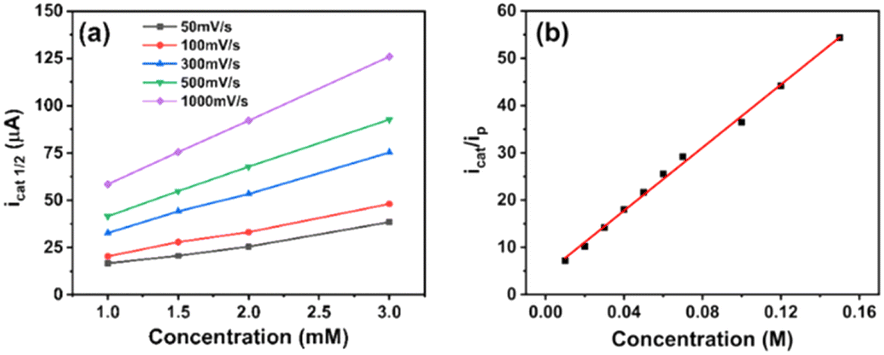 | ||
| Fig. 6 Plot of icat1/2 (half-way catalytic current) in the function of the concentration of NiL complex at different potential scan rates in the presence of 7 0 mM acetic acid as the proton source (a). A plot of icat/ip as a function of acetic acid concentration while using 1 mM NiL, the potential scan rate of 50 mV s−1 (b). | ||
To determine the kinetic parameters, the mechanistic pathway for HER needs to be proposed first. As aforementioned in the potential polarization curve analysis, the first step of H2 evolution catalysis was assigned for the protonation of NiL complex (denoted hereafter as C for the chemical step) and this intermediate underwent one-electron reduction to obtain the NiI species (denoted hereafter as E for the electron-transfer step).
This NiI complex experienced the second CE process resulting in the evolution of the H2 molecule.42–46 In other words, the H2 evolution occurred on the NiL catalyst via a CECE mechanism (Scheme 3). Although the CECE mechanism is not as popular as the ECEC one, CECE was evoked for some nickel molecular catalysts.31,33,35 Based on the above catalytic pathway, there are two approaches commonly used for the estimation of catalytic rate constant and maximal turnover frequency (TOFmax), foot-of-the-wave analysis (FOWA) and plateau current analysis (PCA). Despite benefits when investigating electrocatalysts under the non-pure kinetic condition47 (or S-shaped catalytic wave), Grapperhaus indicated that FOWA was not suitable for the complexes involving the initial protonation step in the HER mechanism (CECE or CCEE).41 PCA was suggested as an alternative method when studying the kinetics of the catalytic operation. One drawback of this calculation is the absence of a perfect S-shaped catalytic wave, however, it is still useful for the preliminary assignment of the catalytic performance.
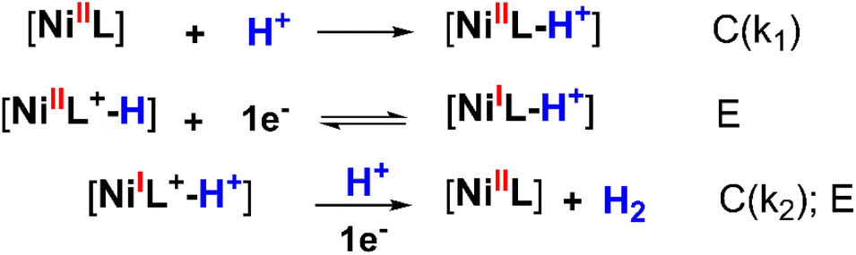 | ||
| Scheme 3 CECE mechanism proposed for the H2 evolution on NiL catalyst (wherein [NiI] and [NiII] represented the active sites). | ||
For such a CECE mechanism, the relationship between the rate constant and the ratio of the catalytic current over the peak current is described by eqn (1) (ref. 41) wherein icat is the catalytic current (mA), ip is the cathodic peak current (mA), R = 8.314 J mol−1 K, T = 299 K, F = 96485 C mol−1, ν is scan rate (V s−1), and kobs = kcat[H+]2 (s−1).
 | (1) |
To decrease the restriction of substrate consumption (acetic acid), we expanded the quantity of the acid concentration to 150 mM to ensure that icat was not limited by substrate diffusion. It means that the catalytic wave could achieve zone KD.47,48 The calculation of kobs values and corresponding kcat values are shown in Table S1.† The changing trend of catalytic rate constants can be observed clearly in Fig. 7.
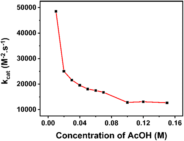 | ||
| Fig. 7 kcat extracted from PCA in various concentrations of acetic acid. | ||
At lower concentrations of the H+ substrate, there is a competition between the consumption of the H+ substrate by the rate-determining step and the diffusion of new H+ substrate to the electrode. The depletion of the acid led to a high rate of catalysis. With the concentration of acetic acid over 100 mM, the rate constant values attained the plateau, implying that the catalyst operates under the condition of no substrate consumption (reached zone KD). In other words, the catalyst has gradually approached the “pure kinetic” zone, so the reaction rate has slowed down and reached an average catalytic rate constant of about 12860 M2− s−1. Therefore, the TOFmax value approximates kcat[AA]2 and could be extrapolated to be 12860 s−1 for 1 M acetic acid concentration.
Conclusions
To conclude, an unusual imine-type nickel complex (NiL) was prepared. The product was generated by the complexation of nickel salt with the in situ formed L ligand (L is 2-(iminomethyl)phenol). The structure of the NiL complex was determined by physical methods (NMR; IR; Raman; UV-vis and elemental analysis). In a DMF electrolyte solution, using this NiL complex as an electrocatalyst and in the presence acetic acid as a proton source, the catalytic H2 evolution emerged at potential close to that of NiII/NiI reduction. Bulk electrolysis at −2.05 V vs. Fc+/0 produced H2 gas with a faradaic yield of 49%. Non-unity faradaic yield was due to the competition between the catalytic H+ reduction generating H2 and the 2-electron reduction of the free-imine group in the L ligand. Based on the proposed CECE mechanism for the H2 evolution, theoretical PCA analysis allowed quantifying the rate constants and maximal turnover frequency of NiL catalyst; with 1 M acetic acid, TOFmax was estimated to be about 12860 s−1.
Data availability
The data supporting this article have been included as part of the ESI.†Author contributions
All authors have given approval to the final version of the manuscript.Conflicts of interest
There are no conflicts to declare.Acknowledgements
This research was funded by University of Science and Technology of Hanoi under the grant number USTH.FAS.01/23-24References
- J. O. Abe, A. P. I. Popoola, E. Ajenifuja and O. M. Popoola, Int. J. Hydrogen Energy, 2019, 44, 15072–15086 CrossRef CAS.
- A. I. Osman, N. Mehta, A. M. Elgarahy, M. Hefny, A. Al-Hinai, A. a. H. Al-Muhtaseb and D. W. Rooney, Environ. Chem. Lett., 2022, 20, 153–188 CrossRef CAS.
- T. T. Le, P. Sharma, B. J. Bora, V. D. Tran, T. H. Truong, H. C. Le and P. Q. P. Nguyen, Int. J. Hydrogen Energy, 2024, 54, 791–816 CrossRef CAS.
- S. Wang, A. Lu and C.-J. Zhong, Nano Convergence, 2021, 8, 4 CrossRef CAS PubMed.
- M. Wang, L. Chen and L. Sun, Energy Environ. Sci., 2012, 5, 6763–6778 RSC.
- V. S. Thoi, Y. Sun, J. R. Long and C. J. Chang, Chem. Soc. Rev., 2013, 42, 2388–2400 RSC.
- J. R. McKone, S. C. Marinescu, B. S. Brunschwig, J. R. Winkler and H. B. Gray, Chem. Sci., 2014, 5, 865–878 RSC.
- I. Roger, M. A. Shipman and M. D. Symes, Nat. Rev. Chem, 2017, 1, 0003 CrossRef CAS.
- J. Mohammed-Ibrahim and X. Sun, J. Energy Chem., 2019, 34, 111–160 CrossRef.
- D. Zhang, J. Z. Soo, H. H. Tan, C. Jagadish, K. Catchpole and S. K. Karuturi, Adv. Energy Sustainability Res., 2021, 2, 2000071 CrossRef CAS.
- J. D. McCool, S. Zhang, I. Cheng and X. Zhao, Chin. J. Catal., 2022, 43, 3019–3045 CrossRef CAS.
- W. Lubitz, H. Ogata, O. Rüdiger and E. Reijerse, Chem. Rev., 2014, 114, 4081–4148 CrossRef CAS PubMed.
- N. A. Eberhardt and H. Guan, Chem. Rev., 2016, 116, 8373–8426 CrossRef CAS PubMed.
- S. J. C. Robinson and D. M. Heinekey, Chem. Commun., 2017, 53, 669–676 RSC.
- G.-G. Luo, H.-L. Zhang, Y.-W. Tao, Q.-Y. Wu, D. Tian and Q. Zhang, Inorg. Chem. Front., 2019, 6, 343–354 RSC.
- L. Tong, L. Duan, A. Zhou and R. P. Thummel, Coord. Chem. Rev., 2020, 402, 213079 CrossRef CAS.
- J.-W. Wang, W.-J. Liu, D.-C. Zhong and T.-B. Lu, Coord. Chem. Rev., 2019, 378, 237–261 CrossRef CAS.
- L. Chen, G. Chen, C.-F. Leung, S.-M. Yiu, C.-C. Ko, E. Anxolabéhère-Mallart, M. Robert and T.-C. Lau, ACS Catal., 2015, 5, 356–364 CrossRef CAS.
- Y.-X. Zhang, L.-Z. Tang, Y.-F. Deng and S.-Z. Zhan, Inorg. Chem. Commun., 2016, 72, 100–104 CrossRef CAS.
- H. Shao, S. K. Muduli, P. D. Tran and H. S. Soo, Chem. Commun., 2016, 52, 2948–2951 RSC.
- X.-S. Hong, D. Huo, W.-J. Jiang, W.-J. Long, J.-D. Leng, L. Tong and Z.-Q. Liu, ChemElectroChem, 2020, 7, 4956–4962 CrossRef CAS.
- C.-L. Wang, H. Yang, J. Du and S.-Z. Zhan, Int. J. Hydrogen Energy, 2021, 46, 32480–32489 CrossRef CAS.
- A. Barma, A. Sarkar, S. Roy, B. Show and P. Roy, ChemistrySelect, 2023, 8, e202302725 CrossRef CAS.
- H. Jadamus, Q. Fernando and H. Freiser, J. Am. Chem. Soc., 1964, 86, 3056–3059 CrossRef CAS.
- G. Mukherjee, S. N. Poddar and K. Dey, Transition Met. Chem., 1987, 12, 323–327 CrossRef CAS.
- T. H. To, D. B. Tran, V. Thi Thu Ha and P. D. Tran, RSC Adv., 2022, 12, 26428–26434 RSC.
- D. Tomczyk, L. Nowak, W. Bukowski, K. Bester, P. Urbaniak, G. Andrijewski and B. Olejniczak, Electrochim. Acta, 2014, 121, 64–77 CrossRef CAS.
- A. J. Fry and R. G. Reed, J. Am. Chem. Soc., 1969, 91, 6448–6451 CrossRef CAS.
- D. K. Root and W. H. Smith, J. Electrochem. Soc., 1982, 129, 1231 CrossRef CAS.
- A. Wang, X. Liu, W. Gao, L. Ma, S. Liu, G. Zhang, M. Zhou, X. Jia and J. Chen, Chem. Commun., 2022, 58, 9906–9909 RSC.
- C.-B. Li, Y. Chu, J. He, J. Xie, J. Liu, N. Wang and J. Tang, ChemCatChem, 2019, 11, 6324–6331 CrossRef CAS.
- T. Straistari, J. Fize, S. Shova, M. Réglier, V. Artero and M. Orio, ChemCatChem, 2017, 9, 2262–2268 CrossRef CAS.
- Z. Han, L. Shen, W. W. Brennessel, P. L. Holland and R. Eisenberg, J. Am. Chem. Soc., 2013, 135, 14659–14669 CrossRef CAS PubMed.
- D. Hong, Y. Tsukakoshi, H. Kotani, T. Ishizuka, K. Ohkubo, Y. Shiota, K. Yoshizawa, S. Fukuzumi and T. Kojima, Inorg. Chem., 2018, 57, 7180–7190 CrossRef CAS PubMed.
- K. Majee, J. Patel, S. Rai, B. Das, B. Panda and S. K. Padhi, Phys. Chem. Chem. Phys., 2016, 18, 21640–21650 RSC.
- J. Singh, G. Hundal and R. Gupta, Eur. J. Inorg. Chem., 2008, 2008, 2052–2063 CrossRef.
- J. Hessels, F. Yu, R. J. Detz and J. N. H. Reek, ChemSusChem, 2020, 13, 5625–5631 Search PubMed.
- A. M. Appel and M. L. Helm, ACS Catal., 2014, 4, 630–633 CrossRef CAS.
- V. Fourmond, P.-A. Jacques, M. Fontecave and V. Artero, Inorg. Chem., 2010, 49, 10338–10347 Search PubMed.
- A. Barma, M. Chakraborty, S. K. Bhattacharya, P. Ghosh and P. Roy, Mater. Adv., 2022, 3, 7655–7666 RSC.
- A. Z. Haddad, S. P. Cronin, M. S. Mashuta, R. M. Buchanan and C. A. Grapperhaus, Inorg. Chem., 2017, 56, 11254–11265 CrossRef CAS PubMed.
- T. L. James, L. Cai, M. C. Muetterties and R. H. Holm, Inorg. Chem., 1996, 35, 4148–4161 CrossRef CAS PubMed.
- O. R. Luca, J. D. Blakemore, S. J. Konezny, J. M. Praetorius, T. J. Schmeier, G. B. Hunsinger, V. S. Batista, G. W. Brudvig, N. Hazari and R. H. Crabtree, Inorg. Chem., 2012, 51, 8704–8709 Search PubMed.
- Y. Han, H. Fang, H. Jing, H. Sun, H. Lei, W. Lai and R. Cao, Angew. Chem., Int. Ed., 2016, 55, 5457–5462 CrossRef CAS PubMed.
- R. Jain, A. A. Mamun, R. M. Buchanan, P. M. Kozlowski and C. A. Grapperhaus, Inorg. Chem., 2018, 57, 13486–13493 CrossRef CAS PubMed.
- S. Chakrabarti, S. Sinha, G. N. Tran, H. Na and L. M. Mirica, Nat. Commun., 2023, 14, 905 CrossRef CAS PubMed.
- K. J. Lee, N. Elgrishi, B. Kandemir and J. L. Dempsey, Nat. Rev. Chem, 2017, 1, 0039 CrossRef CAS.
- E. S. Rountree, B. D. McCarthy, T. T. Eisenhart and J. L. Dempsey, Inorg. Chem., 2014, 53, 9983–10002 Search PubMed.
Footnote |
| † Electronic supplementary information (ESI) available. See DOI: https://doi.org/10.1039/d4ra08116a |
| This journal is © The Royal Society of Chemistry 2025 |